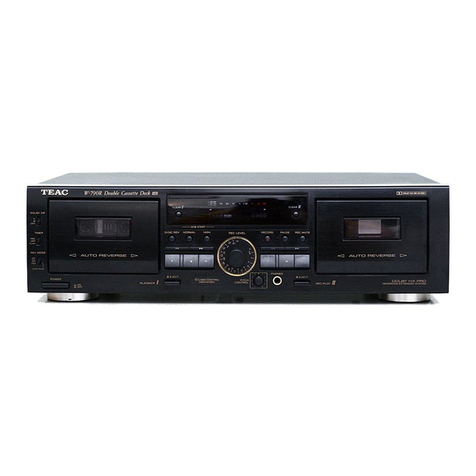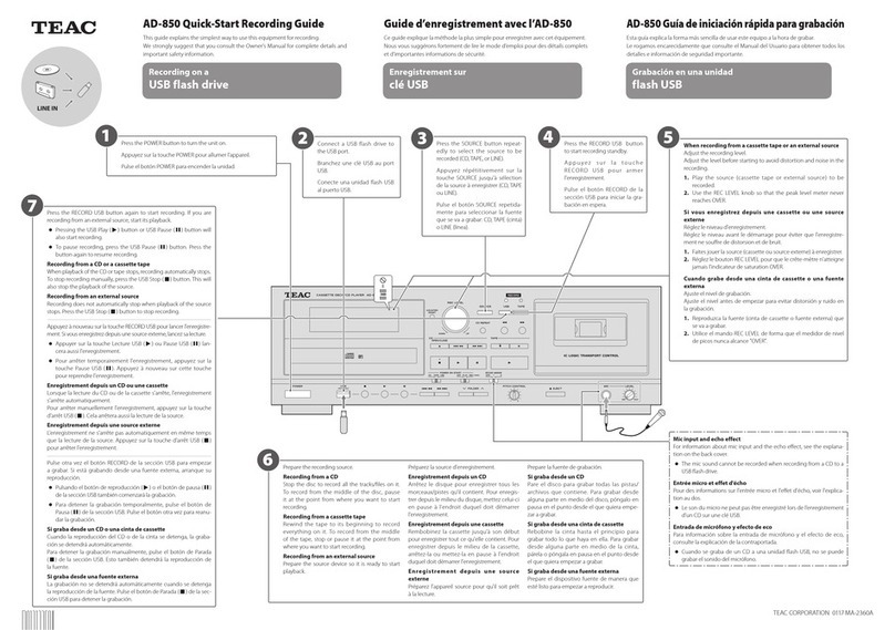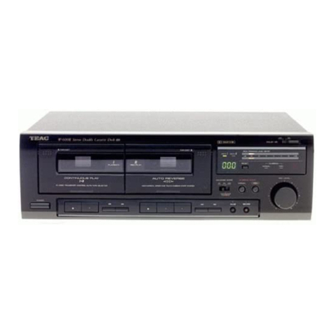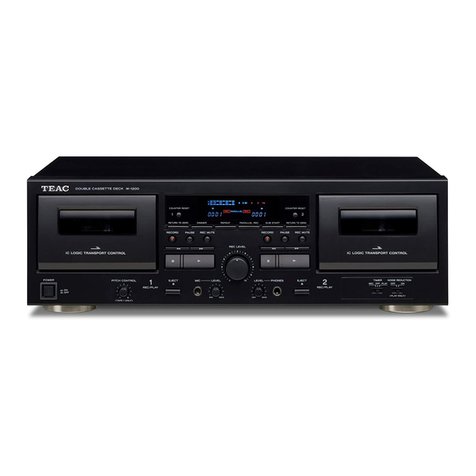
Features and Controls (Fis. 2 and 3)
O POWE R Switch
Press this switch to turn the deck's power
0N. Pressing it again turns the power off .
The deck draws nominal non-operating
power from the AC outlet with its
POWER switch in the 0FF position.
0bs! ndtstrdmstiillareii skiljer ej hela
apparaten fran ndtet.
€) otREcTl0N select switch
(PLAY I, HEC/PLAY II)
Press this down to change the tape running
direction. Each time the switch is operated,
the head rotates by 180 degrees and the
tape running direction is reversed.
@ Rf Vf nSE M0DE Switch
(PLAY I, REC/PLAY II)
The setting of this switch determines how
the deck will operate during playback or
recording when the end of tape is reached.
- (0ne-way): ln this position, playback
or recording will be released when the end
of tape is reached.
- (Reverse): With the REVERSE MODE
switch set to this position, when the end of
tape is reached during playback or recording
in the reverse direction, the playback or
recording mode will be released. During
playback or recording in the fonruard dirc-
tion, the tape running direction will be
reversed when the end of tape is reached,
and reverse playback or recording will be
continued to the end of the other side, at
which point the playback or recording mode
will be released.
cJ (Continuous): With the switch set to
this position, during either forward 0r
reverse play, when the end of tape is
reached, the tape running direction will be
reversed and playback will continue in the
opposite direction. This operation will be
repeated over and 0ver again until the
ST0P/EJECT button is pressed.
lf the recording or dubbing is performed
onto the tape in the REC/PLAY ll mecha-
nism with the switch set to this position,
the lever will return to the:=(reverse)
position automatically and operations will
be the same as with the button set to the
rl (reverse) position.
O Direction lndicators (HEV/FWD)
(PLAY I, REC/PLAY II)
0ne of these indicators lights to show the
current tape running direction. "R EV"
lights during playback or recording in the
reverse direction, and "FWD" lights
during running in the forward direction.
€) Casette Holder (PLAY l, REC/
PLAY II)
When the tape is stopped, pressing the
ST0P/EJECT button opens the cassette
holder door. (PLAY I deck is exclusively for
playback, while REC/PLAY ll deck can be
used for both playback and recording.)
G) Tape Operations Buttons (PLAY l,
REC/PLAY II}
When the end of tape is reached, the tape
transport automatically stops, unless the
PAUSE button is engaged.
PLAY ( > ) Button: P1s5s t0 start playback
at normal speed.
BEW (<< ) Button: Press to rewind the
tape at high speed.
F.FWD (>> ) Button: Press to advance the
tape at high speed.
ST0Pi EJECT ( ! /: ) Button: Press to
stop the tape travel and release any mode
other than the pause mode. Press this
button in the stop mode to open the
cassette holder door.
PAUSE ( lt ) Button: Press to temporarily
stop tape travel during playback or record-
ing. Press again to resume tape travel.
BECOBD (o ) Button (REC/PLAY ll
only): Pres to initiate recording or dubbing.
The "REC0 RD" indicator will light.
Note: Recording is not possible if the erase
protection tab has been removed
from the cassette.
O nf COHD Level Control
This control is used to adjust the levels of
the left and right input signals simultaneous-
ly when recording. Adjust so that the peak
value occasionally reaches "0tt - "+3" dB.
The setting of this control has no effect
during dubbing.
O ouBBtNG switch
Pres this button to on ( o ) when dubbing
from PLAY lto REC/PLAY ll.
O OUB SPEED Switch
HIGH (o ): Set to this position when
quick dubbing is required (approx. 2 times
faster than normal speed dubbing).
N0BMAL ( trI ): Set to this position when
normal speed dubbing is required.
Note: Make sure the DUBBING button is
set to 0FF ( EI ) when dubbing is
not required.
@ nnlC Jacks (L/R)
Plug microphones into these jacks when you
want to record using microphone. "L" is
for the left channel and "R" for the right
channel. When the microphones are inserted
into these jacks, the input signal from the
LINE lN jacks on the rear panel will be
automatically cut off. Microphones with
impedances from 200 ohms to 10k ohms
will give the best results, but 150-ohm to
200-ohm microphones can also be used.
O PH0NES (Headphones) Jack
Connbct 8-ohm stereo headphones to this
jack for private listening or monitoring.
@ ooLBY NR Switches
lN/0UT Switch: This switch is used to
activate and deactivate the noise reduction
system. To activate noise reduction, set to
the lN ( o ) position and select the NR-
system with the UU B/ DC C switch. Set
this switch to the OUT ( trI ) position to
record or play back without n0ise reduction.
D0 B/ DC C Switch: Set this switch to the
tt D t' position to record with Dolby
C-type NR or play back a cassette tape re-
corded with Dolby C-type NB', or to the
tt g " position to record with Dolby
B-type N R or play back a cassette tapes re-
corded with Dolby B-type NR.
Note: These have no effect during dubbing
from PLAY I to REC/PLAY llwhen
the D U BB lN G switch is engaged.
(DTAPE C0UNTER with Reset
Button (REC/PLAY ll only)
The tape counter indicates the relative
position of the tape loaded in the R EC/
PLAY I I deck. Press the button to reset
the counter 10 "000".
(D PTNT PROGRAM LEVEL METER
This indicator shows the peak levels of the
signals for both channels simultaneously.
ln the record mode, it shovrn the level of the
signals input to the LINE lN jacks on the
rear panel, and these can be adjusted with
the REC0RDING LEVEL control. ln the
playback m0de, the meter indicates the
level of the signals picked up from the tape.
(D 0peration lndicators
DUBBING: This indicator lights when the
DUBBING switch is pressed to 0N.
Hl-SPEED: This indicator lights when the
DUB SPEED switch is set to the HIGH
position.
REC0RD: This indicator lights when the
REC/PLAY ll deck is in the record mode.
(D 0oLBY NR lndicators
When the D0LBY NR switches are set for
Dolby C-type NR (lttl and DC C), the
DU C indicator will light, and when they
are set f or D0 LBY B-type N R (lN and
DC B), the Dfl B indicator will light.
(D t-tNE lN and 0UTPUT Terminals
@ ntN lN/0UT Socket (for Europe
models only)
Models for Europe are equipped with a
DIN socket for use with amplifiers that do
not have RCA-type pin jack c0nnectors.
When DIN-to-DlN cord is inserted into this
socket, the line input signals from the LIN E
lN jacks arc cut off.
Note: When using the DIN cable for con-
nection, make sure to use a Pre-
wired quality one.
(D Voluge Selector (General export
models only)
See "Voltage Conversion" on page 3.
-5-


