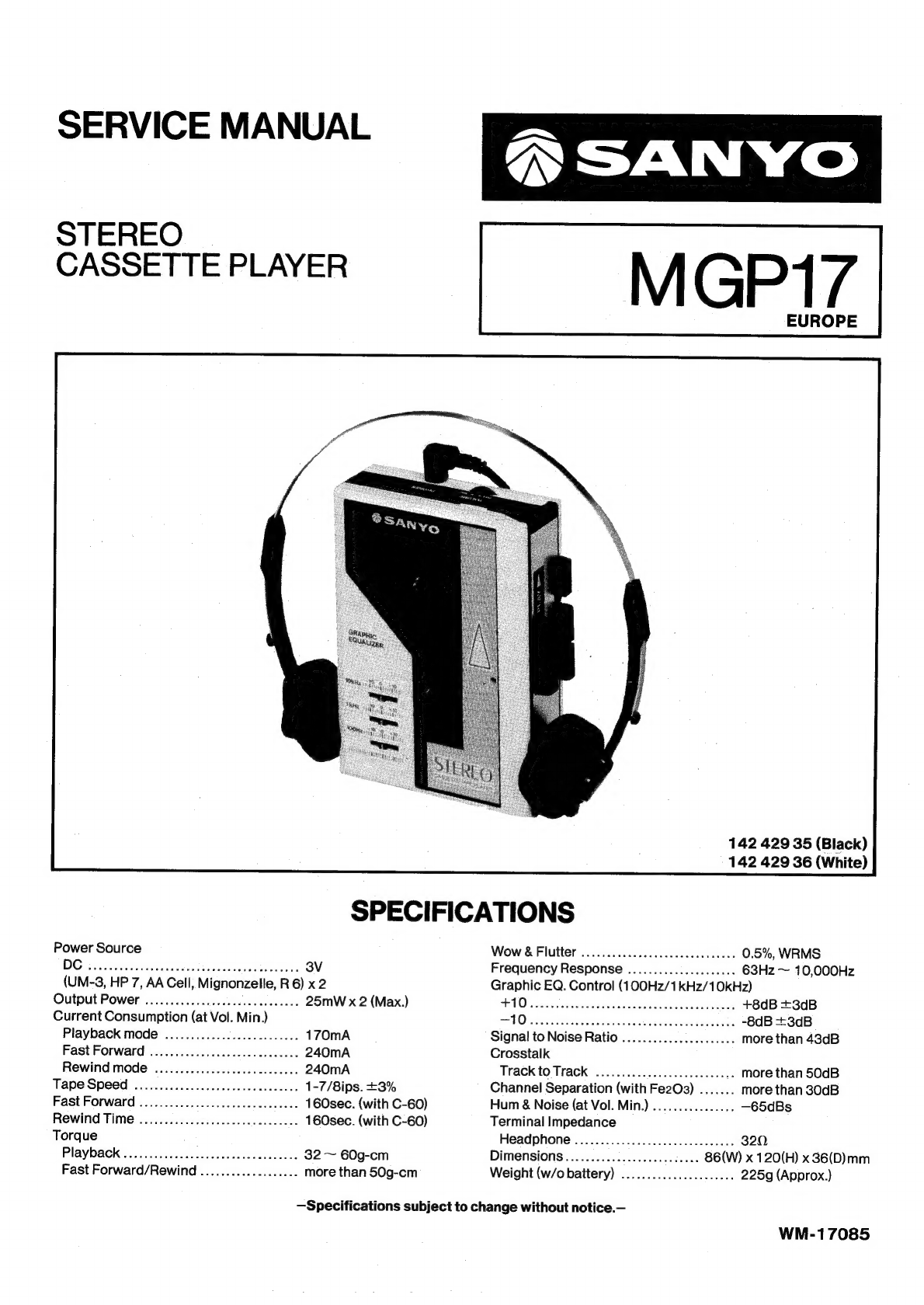
Sanyo MGP17 User manual

SERVICE
MANUAL
STEREO
CASSETTE
PLAYER
SANYO
MGP17
EUROPE
142
429
35
(Black)
142
429
36
(White)
SPECIFICATIONS
Power
Source
DG
snttinoxan
Sach
dhiSectn
alee
dees’
3V
(UM-3,
HP
7,
AA
Cell,
Mignonzelle,
R
6)
x
2
Output
Power
..............cebeccceeseecees
25mW
x
2
(Max.)
Current
Consumption
(at
Vol.
Min.)
Playback
mode
............0.....cceceeee
170mA
Fast
Forward
.............cc.ccceceseacees
240mA
Rewind
mode
....................cceceees
240mA
Tape
Speed
ooo...
cece
cee
eceeeeeeeeeees
1-7/8ips.
+3%
Fast
Forward
................cccececnceusece
160sec.
(with
C-60)
Rewind
Time
..............c.cceeeeseceees
160sec.
(with
C-60)
Torque
Playback
.........c.ccccsceceseeceeeueeeees
32
~
60g-cm
Fast
Forward/Rewind
...................
more
than
50g-cm
Wow
&
Flutter
................cceeseeeseeeee
0.5%,
WRMS
Frequency
Response
.....................
63Hz
~
10,000Hz
Graphic
EQ.
Control
(100Hz/1kHz/10KHz)
UO
assacsidavicagserdsedes
eget
secede
sectors
+8dB
+3dB
Ove
Sits
8
Shes
behets
Ponts
ieeeteasee
ce
-8dB
+3dB
Signal
to
Noise
Ratio
..........0.0.........
more
than
43dB
Crosstalk
Track
to
Track
...........................
more
than
50dB
Channel
Separation
(with
Fe2O3)
.......
more
than
30dB
Hum
&
Noise
(at
Vol.
Min.)
...........2....
—65dBs
Terminal
Impedance
Headphone
................ccccceeeceeeaes
320,
Dimensions
...............0.e.cccaeas
86(W)
x
120(H)
x
36(D)mm
Weight
(w/o
battery)
.............0.....008
225g
(Approx.)
—Specifications
subject
to
change
without
notice.—
WM-17085

DISASSEMBLY
INSTRUCTIONS
GENERAL
REMARKS
@
Before
disassembling
the
unit,
spread
a
soft
rubber
mat
ora
cloth
on the
workbench
to
avoid
scratches
and
grease
stains.
@
Do
not
use
a
material
which
is
likely
to
cause
static
electricity
because
transistors
and
ICs
may
be
easily
damaged
by
it.
Reassemble
the
unit,
noting
the
kinds
of
screws,
the
soldering
and
arrangement
of
the
leads.
Refer
to
“Circuit
Diagram
and
Exploded
Views’
for
correct
assembly.
Before
‘disassembling
the
unit,
take
out
the
cassette
tape
and
the
batteries.
CABINET
BOTTOM
REMOVAL
1.
Open
the
Cassette
Compartment
Lid
by
pressing
the
Stop
Button
and
take
out
the
cassette
tape
from
the
compartment.
Turn
over
the
unit
with
the
front
side
down
on
a
soft
surface
and
remove
the
Battery
Compartment
Lid.
Then,
remove
the
batteries.
Remove
the
four
screws
(1
~
4)
fastening
the
Cabinet
Bottom
and
lift
the
Cabinet
Bottom
away
from
the
unit.
Cabinet
Bottom
©
4.
Reassembie
in
reverse
order.
P.C.BOARD
REMOVAL
1.
Remove
the
Cabinet
Bottom
by
following
the
instructions
for
the
“Cabinet
Bottom
Removal”.
Unsolder
the
FPC
of
the
Graphic
Equalizer
from
the
P.C.Board.
Remove
the
screw
(5)
fastening
the
P.C.Board.
Turn
over
the
P.C.Board
in
the
direction
of
the
arrow
with
caution
not
to
damage
the
Playback
Head
and
Motor
leads.
ni
.
Reassemble
in
reverse
order.
NOTE:
When
mounting
the
Amplifier
P.C.Board,
check
to
see
that
the
power
switch
operates
correctly
by
pressing
the
Play
Button.
CASSETTE
MECHANISM
REMOVAL
.
Remove
the
P.C.Board
by
following
the
instructions
for
“Cabinet
Bottom
Removal”
and
“P.C.Board
Removal”.
2.
Remove
the
three
screww
(6
~
8)
holding
the
Cassette
Mechanism.
3.
To
detach
the
Cassette
Mechanism,
lift
the
Mechanism
in
the
direction
of
the
arrow.
4.
Reassemble
in
reverse
order.

ADJUSTMENT
PROCEDURES
GENERAL
REMARKS
3.
While
Playing
back
the
test
tape,
adjust
the
tape
speed
by
©
Before
adjusting
the
mechanism
of
this
unit,
wipe
the
tape
turning
the
potentiometer
(P401)
on
the
P.C.Board
with
an
contacting
surfaces
of
the
Head,
Pinch
Roller
and
Capstan,
alignment
tool
until
the
frequency
counter
reads
3kHz.
and
the
surfaces
of
the
driving
parts
Such
as
the
Drive
Belt,
Take-up
Belt,
Flywheel
and
Pulley
with
a
soft
cloth
soaked
in
alcohol.
Trouble
may
occur
because
of
oil
and
grease
stains.
©
Carefully
handle
the
belt
because
grease
easily
attaches
to
it.
Then,
check
the
used
rubber
parts.
If
the
rubber
has
deteriorated
or
is
Scratched,
replace
the
Parts
with
new
ones.
EQUIPMENT
REQUIRED
©
Frequency
Counter
Dualtrace
Oscilloscope
VTVM
(2
sets)
Dummy
Load
(32:0)
Test
Tapes
#
3kHz
test
tape
(Example:
TEAC
MTT-111)
for
the
Tape
Speed
Adjustment
*
10kHz
test
tape
(Example:
TEAC
MTT-114)
for
the
Head
HEAD
AZIMUTH
ADJUSTMENT
Azimuth
Adjustment
1.
Connect
two
VTVMs
and
a
dualtrace
Oscilloscope
to
the
©
Alignment
Too!
Headphone
Jack
as
illustrated,
NOTE:
Set
the
osci
lloscope
as
follows:
Before
the
Electrical
Adjustments,
set
the
Switch
and
EM
ODE
siscasntpsi
tir
scnesslecicve:
CHOP
(chopped)
Control
as
follows:
B
SQURCE
kee
elt
cuag
i
«:
INT
(internal),
CH1
or
CH2
¥
VOLUME
COMLNOL
sseevsssessdovisaresoasedectessec:
As
desired
PSWEEP
MODE
o.oo
occcscccscscas
cs...
AUTO
(automatic)
#
Graphic
EQ.
Controls
«00...
0
(click
position)
#
Install
new
two
batteries
to
the
battery
compartment
for
the
adjustment.
TAPE
SPEED
ADJUSTMENT
1.
Remove
the
Battery
Compartment
Lid
and
take
out
the
batteries
from
the
compartment,
and
connect
the
regulated
DC
3V
power
Supply
to
the
Ext.
Power
Jack.
2.
Connect
a
frequency
counter
to
the
Headphones
Jack
as
illustrated
and
insert
a
3kHz
test
tape
(Example:
TEAC
MTT-111)
into
the
Cassette
Compartment.
Frequency
Counter
LJoloooigo]
a
[Fic
cong:
Gd
:
I
PHONES
2.
Insert
a
10kHz
test
tape
(Example:
TEAC
MTT-114)
into
the
Cassette
Compartment
and
play
it
back.

ADJUSTMENT
PROCEDURES
(continuea)
3.
While
playing
back
the
test
tape,
slowly
turn
the
azimuth
adjusting
screw
until
the
amplitudes
of
both
channel
output
waveforms
become
maximum
and
the
waveforms
overlap
as
well
as
possible
as
illustrated.
:
Then
the
VTVMs
must
be
read
at
the
maximum
as
much
as
possible.
Azimuth
Adjusting
Screw
4.
After
the
adjustment,
secure
the
adjusting
screw
with
paint
or
glue.
PARTS
LIST
fet.
Part
No.
Description
Q’ty
oe
Part
No.
Description
Q’ty
PACKAGE
CA8
141-2-4219-30001
Screw,
+M1.7x10.0
(Black)
6
141-6-1419-88602
Individual
Carton
1
CA8
141-2-4219-30001
Screw,
+M1.7x10.0
(White)
2
141-6-1469-13300
Case
Styrofoam
1
CA8-1
141-2-4219-30002
Screw,
+M1.7x10.0
(White)
4
141-6-2519-12090
Poly
Cover
1
CAQ
141-2-3829-45200
Spring
Battery
1
141-6-3919-52100
Plain
Pad
1
CA10
—-
141-2-1639-63200
Knob
Volume
1
141-6-4559-03300
Serial
No.
Sheet
3
CAI
141-2-3829-45100.
Spring
Battery
Anode
1
141-6-4559-03979
Label
Color
BK
(Black)
1
CA12
—-141-2-1339-38000
Lid
Battery
(Black)
1
141-6-4559-03952
Label
Color
W
(White)
1
CA12
141-2-1339-38003
Lid
Battery
(White)
1
CA13.
—s-
141-2-4419-20100
Sheet
3
CA14.
—
141-2-1129-41403
Cabinet
Bottom
(Black)
1
ACCESSORIES
CA14
—«-141-2-1129-41404
Cabinet
Bottom
(White)
1
¢
4-1529-70671
Headphones
1
142-6-4119-32947
Instruction
Book
1
Cx1
128-3-1314-04018
Pl
Screw-3,
Pan
Hd.,
+M1.4x4.0
1
CX2
428-3-1317-04014
Pl
Screw-3,
Pan
Hd.,
+M1.7x4.0
1
CX3
443-3-1302-00618
Screw,
Pan
Hd.
Tapping-B,
+M2.0x6
1
CABINET
Cx4
110-3-2101-70013
Spring
Washer-2,
M1.7
1
CAI
141-0-1249-40002
Lid
Cassette
Assy
(Black)
1
CAI
141-0-1249-40003
Lid
Cassette
Assy
(White)
1
PCBI1
141-0-1939-14001
Amplifier
P.C.B.
Assy
1
CA2
4-2262-25860
FPC,
Equalizer
i
PCB2
_
141-0-1939-14130
Graphic
Equalizer
P.C.B.
Assy
1
CA3
141-2-3659-21900
Holder
Equalizer
(Black)
1
CA3
—_—-141-2-3659-21901
Holder
Equalizer
(White)
1
NOTE:
CA4
—141-2-4219-21700
Screw,
+M1.4x4.0
3
1.
Parts
order
must
contain
Model
Number,
Part
Number
and
CAS
141-2-8549-17200
Spring
Eject
1
Description.
CAG
141-2-1419-18615
Rating
Plate
1
2.
Ordering
quantity
of
screws
and
resistors
must
be
multiple
of
CA?
141-0-1129-18300
Cabinet
Top
Assy
1
10
pcs.
Adjustment

CABINET
EXPLODED
VIEW
—5—
CA8
(Black)
(Red)
S—
CA8-1
(White)
(Blue)
(Yellow)
CA8-1
(White)
(Blue)
(Yellow)
Ref.
No.
Part
No.
HEADPHONES
PARTS
LIST
Description
Q’ty
HEADPHONES
4-1529-70671
141-0-1769-01701
141-2-1259-10300
141-2-1259-10400
4-1529-70680
141-2-4469-55800
4-2369-76090
anh
wh
~~
+
NOTES:
Headphones
-
Headphone
Band
Assy
Housing
Left
Housing
Right
Ear
Speaker
Ear
Pad
Plug
Cord
|anne--
—
1.
Parts
order
must
contain
Model
Number,
Part
Number
and
Description.
HEADPHONES
EXPLODED
VIEW

MECHANISM
PARTS
LIST
ner
Part
No.
Description
Q’ty
MECHANISM
MC1
141-0-3119-25000
Chassis
Assy
1
MC2
141-2-4459-33400
Cushion
Motor
1
MC3
4-5279-71470
Motor
[M1]
1
MC4
141-0-7419-42600
Lever
Play
Assy
1
MC5
141-2-3529-46200
Head
Base
1
MC6
141-2-8519-47400
Spring
Head
1
MC7
141-4-2429-72390
Playback
Head
[HD1]
1
MC8&
141-2-4219-24500
PC
Screw,
Pan
Hd.-3,
+M2.0x4.0
1
MCc9
141-2-8559-02500
Spring
Supply
1
MC10
~—-
141-2-4539-18100
Washer,
M1.6x3.0x0.13
1
MC11
141-0-5369-01901
Reel
Supply
Assy
1
MC12
=
141-2-4539-17500
Washer,
M1.25x3.0x0.25
2
“MC13
=
141-2-4539-30600
Washer,
M1.25x4.0x0.25
1
MC14
=:
141-2-5519-47200
Gear
F.FWD
1
MC15
—-
141-0-5459-02000
Pinch
Roller
Assy
1
MC16
=
141-2-8529-25800
Spring
Pinch
Roller
1
MC17
—-141-2-4539-35000
Washer,
M1.6x3.2x0.4
1
MC18
=
141-2-4539-27601
Washer,
M2.1x3.5x0.13
2
MC19
141-2-8519-07500
Spring
Lever
Stop
1
MC20
=.
141-2-4539-19800
Washer,
M2.1x5.0x0.13
2
MC21
141-0-5219-11900
Flywheel
Assy
1
MC22
=
141-2-5649-25700
_
Belt
Drive
1
MC23
=
141-2-4729-09200
Lug
1
MC24
~—-
141-2-4219-10600
Screw,
+M1.7x4.0
1
MC25
~—s-
141-0-7419-39601
Lever
Stop
Assy
1
MC26
~—-
141-0-7419-39501
Lever
Rewind
Assy
1
MC27
~—s:
141-2-7439-31000
Arm
Review
1
MC28
=
141-2-8529-14600
Spring
Plate
Lock
1
MC29
~—s-:
141-2-3519-64901
Plate
1
MC30
=:
141-2-8549-06800
Spring
Plate
Lock
©
{
MC31
141-2-8519-71200
Spring
2
MC32
=
141-2-4219-29900
Screw,
Pan
Hd.
Tapping-B
+M1.7x4.0
4
MC33
—-
141-2-7439-31100
Arm
Power
1
MC34
+
141-0-5319-07302
Reel
Take-up
Assy
1
MC35
~—s-
141-2-8529-11700
Spring
Cancel
ASO
1
MC36
—-
141-0-3519-21500
Plate
Reel
Assy
1
MC37
—-
141-2-4539-13000
Washer,
M1.6x4.0x0.13
1
MC38
141-2-5519-47000
Pulley
Take-up
1
MC39
=
141-2-5649-09900
Belt
Take-up
1
MC40
=:
141-2-8549-18200
Spring
1
MC41
141-2-7439-30700
Arm
Take-up
1
MC42
141-2-5519-47500
Gear
Take-up
1
MC43.—s-
141-2-4539-15700
Washer,
M1.5x3.5x0.4
1
MC44
~—s-
141-0-7419-39401
Lever
Fast
Assy
1
MC45
~—s-
141-2-5519-47100
Gear
Fast
1
MC46
~—s-:
141-2-7319-57300
Plate
Lock
1
MZ1
101-3-1802-00311
Screw,
Truss
Hd.,
-+M2.0x3
1
MZ2
101-3-3702-00611
Screw,
Bind
Hd.,
=M2.0x6
1
MZ3
128-3-1317-03518
Pl
Screw-3,
Pan
Hd.,
+M1.7x3.5
1
MZ4
112-3-1301-50082
E
Ring,
M1.5
1
NOTES:
1.
Parts order
must
contain
Model
Number,
Part
Number
and
Description.
2.
Ordering
quantity
of
screws
and
resistors
must
be
multiple
of
10
pes.
(Chassis
Top)
MECHANISM
EXPLODED
VIEW
&—mecl2
MC11
mctO
S
mcg
gy
g
o&—we13
MCs
Co
>—wers
do—mz4
MC15

MECHANISM
EXPLODED
VIEW
«continuea)
(Chassis
Bottom)
MC46

P.C.BOARD
PARTS
LIST
Ref.
Part
No.
Description
Q’ty
oer
Part
No.
Description
Q’ty
AMPLIFIER
P.C.B.
ASSY
C602.
=
CG1-8-2500-KHOOB
Chip
Capacitor
0.00184F
50V
+10%
1
PCBI
441-0-1939-14001
Amplifier
P.C.B.
Assy
1
C603
CG2-7-2500-KHOOB
ChipCapacitor
0.0027uF
50V
+10%
1
141-2-4729-05000
Staple,
5mm
;
17
C604
CG8-2-2500-KHOOB
ChipCapacitor
0.00824F
50V
+10%
1
Ji
4-2359-77750
—
Jack
3P
(Headphones)
1
C605
CG1-2-3250-KHOOB
Chip
Capacitor
0.012uF
25V
+10%
1
J2
4-2359-78080
Ext.
Power
Jack
1
C606
CG1-0-3250-KHOOB
Chip
Capacitor
O.01uF
25V
+10%
1
S1
4-2319-76920
Leaf
Switch
(Power)
1
C701
CG1-0-4250-ZI00B
Chip
Capacitor
O1uF
25V
+80-20%
1
P401
4-2229-76480
Potentiometer,
B-2.2k0.
1
R501
401-038-6406
Chip
Resistor
47kQ
10W
+5%
1
VRO1
4-2229-75580
Rotary
Volume
(Volume/A-20kQ)
1
R502
401-037-6803
Chip
Resistor
12kQ
1N0W
+5%
1
TH401
4-2219-70540
Thermistor,
200
1
R503
401-038-9209
Chip
Resistor
6.8kQ
110W
+5%
1
or
204-5-9000-00200
.
Thermistor,
SDT
20
1
R504
401-038-6406
Chip
Resistor
47kQ 110W
+5%
1
10301
4-2069-75070
IC,BA3506A
1
R505
401-038-6406
Chip
Resistor
4.7kQ
110W
+5%
1
1C401
=.
207-5-1895-52310
+
IC,
LA
5523
1
R506
401-038-0800
Chip
Resistor
22kQ
1/10W
+5%
1
C101
=
CC1-0-2500-KEOQ1R
Ceramic
0.001uF
50V
+10%
1
R507
401-037-9309
Chip
Resistor
18kQ
1N0W
+5%
1
C102
CD3-3-663A-0001V
Electrolytic
33uF
6.3V
1
R508
401-037-9309
Chip
Resistor
18kQ
110W
+5%
1
C103.
=
CM2-2-3500-JOOBV
Mylar
0.022uF
50V
+5%
1
R509
401-038-3702
Chip
Resistor
33kQ
1/10W
+5%
1
C104
CD4-7-5500-0001V
Electrolytic
47uF
50V
1
R510
401-038-0800
Chip
Resistor
22kQ
1N0W
+5%
1
C105
CD4-7-5500-0001V
Electrolytic
474F
50V
1
R511
401-037-5806
Chip
Resistor
IMO
110W
+5%
1
C106
CC1-0-2500-KE01R
Ceramic
0.001mF
50V
+10%
1
R601
401-038-6406
Chip
Resistor
47kQ 110W
=+5%
1
C107
~=CT1-0-563A-MO0OAV
Tantalum
wF
63V
+20%
.
1
R602
401-037-6803
Chip
Resistor
12kQ
1/0W
+5%
1
C108
CD2-2-7100-0001V
Electrolytic
220uF
=
10V
1
R603
401-038-9209
Chip
Resistor
6.8kQ 1/10W
+=5%
1
C201
CCi-0-2500-KE01R
Ceramic
0.001MF
50V
+10%
1
R604
401-038-6406
Chip
Resistor
4.7kQ
110W
+5%
1
C202
=
CD3-3-663A-0001V
Electrolytic
33uF
66.3V
1
R605
401-038-6406
Chip
Resistor
4.7kQO
110W
+5%
1
C203.
CM2-2-3500-JOOBV
Mylar
0.022uF
50V
+5%
1
R606
401-038-0800
Chip
Resistor
22k.
10W
+5%
1
C204
=
CD4-7-5500-0001V
Electrolytic
4.74F
=650V
1
R607
401-037-9309
Chip
Resistor
18kQ
110W
+5%
1
C205
CD4-7-5500-0001V
Electrolytic
47uF
50V
1
R608
401-037-9309
Chip
Resistor
18kKQ
1/10W
+5%
1
C206
=
CC1-0-2500-KE01R
Ceramic
0.001MF
50V
+10%
1
R609
401-038-3702
Chip
Resistor
33kQ
1/10W
+5%
1
C207
=
CT1-0-563A-MO0AV
=
Tantalum
1uF
63V
+20%
1
R610
401-038-0800
Chip
Resistor
22k.
10W
=+5%
1
C208
CD2-2-7100-0001V
Electrolytic
220uF
=10V
1
R611
401-037-5806
Chip
Resistor
1MQ
110W
+5%
1
C301
CD3-3-663A-0001V
Electrolytic
33uF
6.3V
1
C302
=
CD2-2-7100-0001V
Electrolytic
220MF
=10V
1
C303
CD2-2-7100-0001V
Electrolytic
220uF
=
10V
1
NOTES:
C304
CD2-2-7100-0001V
Electrolytic
220MF
=10V
1
1.
Parts order
must
contain
Model
Number,
Part
Number
and
C401
CD2-2-5500-0001V
Electrolytic
2.2uF
50V
1
Description.
C402
—CD2-2-6160-0001V
Electrolytic
22uF
16V
1
2.
Ordering
quantity
of
screws
and
resistors
must
be
multiple
of
R101
401-029-9706
Carbon
2200
1/8W
+5%
1
10
pes.
R102
401-032-0608
Carbon
5.6kQ
1/8W
=5%
1.
R103
401-029-2004
Carbon
150kQ
1/8W =+5%
1
R201
401-029-9706
Carbon
2200
1/8W
+5%
1
R202
401-032-0608
Carbon
5.6kQ
1/8W
+5%
1
R203
401-029-2004
Carbon
150kQ
1/8W
+5%
1
R301
401-031-8308
Carbon
560
1/8W
+5%
1
R302
401-028-3200
Carbon
1kQ
1/8W
+5%
1
R401
401-029-7900
Carbon
2000
1/8W
+5%
1
R402
401-031-2405
Carbon
3.9kQ
1/8W
+5%
1
R403
401-031-6601
Carbon
4.7kQ
1/8W
45%
1
R404
401-032-4606
Carbon
6.8kQ
1/8W
+5%
1
GRAPHIC
EQUALIZER
P.C.B.
ASSY
PCB2
141-0-1939-14130
Graphic
Equalizer
P.C.B.
Assy
141-0-1939-15420
PCB,
Graphic
Equalizer
4-2262-27420
FPC,
Graphic
Equalizer
141-2-2899-55800
Adhesive
Sheet
141-2-4359-42400
Insulator
VR2
4-2229-76390
Slide
Volume
(Equalizer/W-100kQ)
Q501
203-5-4422-81216
Transistor,
2502812
Q601
203-5-4422-81216
Transistor,
2SC2812
C501.
=
CG3-9-1500-KHOOB
Chip
Capacitor
390pF
50V
+10%
C502)
=
CG1-8-2500-KHO0B
ChipCapacitor
0.0018uF
50V
+10%
C503
€CG2-7-2500-KHOOB
ChipCapacitor
0.0027uF
50V
+10%
C504
=
=©CG8-2-2500-KHOOB
ChipCapacitor
0.0082uF
50V
+10%
C505
CG1-2-3250-KHOOB
Chip
Capacitor
0.012uF
25V
+10%
C506
CG1-0-3250-KHOOB
Chip
Capacitor
O.01uF
§=625V
+10%
C601
=
=CG3-9-1500-KHOOB
Chip
Capacitor
390pF
50V
+10%
Pa
ne
a
Car
a
en
on
rr
Cone
Cs
Ce
Cn
—~10—

IC
&
TRANSISTOR
LEAD
IDENTIFICATION
TRANSISTOR
|
FRONT
VIEW
|
BOTTOM
VIEW
28C2812
TERMINAL
NAMES
B—
BASE
C—
COLLECTOR
E—
EMITTER
.
BA3506A
BOTTOM
VIEW
LA5523
FRONT/
BOTTOM
VIEWS
il
}
2
5
BA3506
BLOCK
DIAGRAM
LA5523
BLOCK
DIAGRAM
Bias
PreiN)
=
Pre
NF}
Pre
OUT!
Power
INI
Power
OUT!
Ne
15
|
GND
Vref
OUT}
Vref
OUT
2

AMPLIFIFER
P.C.BOARD
&
WIRING
DIAGRAM
(BOTTOM
VIEW):
3}
14)15
|
16
451.4
|
1.4
1
1.4}
1.4]
1.4
11
|
12
1.44
1.
O
5
eG
(3)
mo
s
°°.
>

SCHEMATIC
DIAGRAM
im
x
TANNVWHO
L337
40
MO}}
[CUB1S
<Q
cs
soso
me
ee
:
TANNVHO
LHDIY
JO
MO|}
[CUBIS
<<ijumaaesumeemsnen
LINDHID
IOYLNOD
¥Y3ZITVNOA
StHdVYS
OL
(LHOIS)
(1337)
NI.
10
GND
2A
10
NI
Ag'9
495
ooze
|
Mee
1028
2029
QV3H
NOVAAV
Id
Tag
lex1730.vv,
+
22-8
*
10rd
#
AINDYEID
YONSZAOD
YOLOW
eg2gsv7
foe
=
Mee
a
YaldIIaWY
YBMOd/
aud
38,
zon
vaoseva
ics!
—~13-—

GRAPHIC
EQ.
CONTROL
P.C.BOARD
VR2
GRAPHIC
EQ
VOLUME
CONTROL
‘8
TO
AMPLIFIER
GRAPHIC
EQ.
CONTROL
SCHEMATIC
DIAGRAM
aso1
2SC2812
R509
3K
N
50,
504
c506
Bar
“i
2
W-10X6
1800P
8200P
Ooty
¢701
Only
FE
E]
oO]
cj]
B)
A
IN
OUT
GND-Vcc
OUT
IN
——____/
TO
AMPLIFIER
SANYO
ELECTRIC
TRADING
CO.,
LTD.
OSAKA,
JAPAN
March/’86/2,200
Printed
in
Japan
Table of contents
Other Sanyo Cassette Player manuals

Sanyo
Sanyo MCD-Z330F User manual

Sanyo
Sanyo MCD-UB575M User manual

Sanyo
Sanyo MCD-Z46K User manual

Sanyo
Sanyo M9998LU User manual

Sanyo
Sanyo TRC-2050C User manual

Sanyo
Sanyo M-X920LU User manual

Sanyo
Sanyo MCD-Z95F User manual

Sanyo
Sanyo MCD-S665F User manual

Sanyo
Sanyo MCD-Z90F User manual

Sanyo
Sanyo MCD-UB575M User manual

Sanyo
Sanyo MCD-Z250F User manual

Sanyo
Sanyo MCH-900F User manual

Sanyo
Sanyo VHR-550 User manual

Sanyo
Sanyo MCD-Z7F User manual

Sanyo
Sanyo MCD-X75L User manual

Sanyo
Sanyo MCD-ZX100F User manual

Sanyo
Sanyo MCD-XJ780A User manual

Sanyo
Sanyo MCD-Z31F User manual

Sanyo
Sanyo MCD-Z155F User manual

Sanyo
Sanyo MCD-s900F User manual