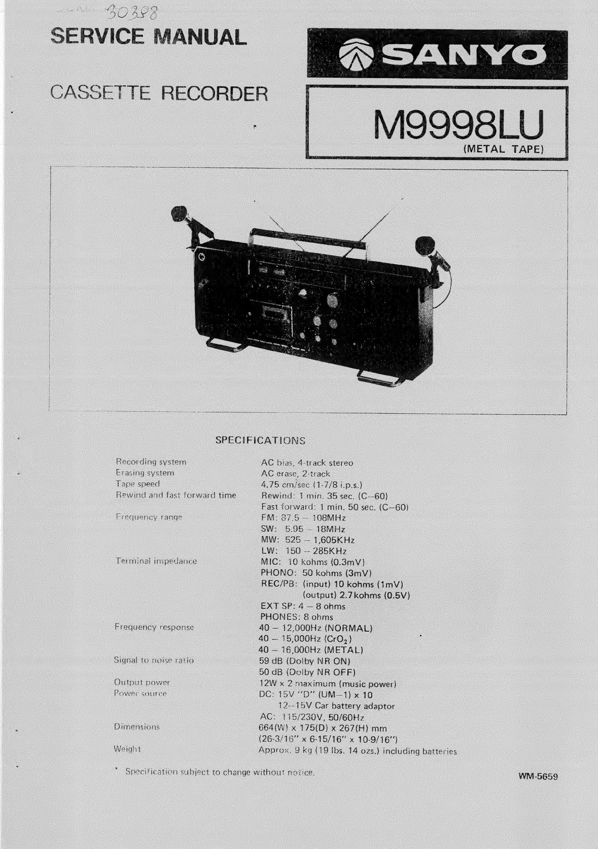
Sanyo M9998LU User manual

SERVICE
MANUAL
CASSETTE
RECORDER
(METAL
TAPE)
i
1
}
;
|
|
|
|
|
|
i
j
i
|
|
'
i
{
H
|
|
:
{
i
\
|
i
t
i
i
|
{
i
|
SPECIFICATIONS
recording
system
AC
bias,
4-track
stereo
Erasing
system
AC
erase,
2-track
Tape
speed
4.75
cm/sec
(1-7/8
i.
p.s.)
Rewind
and
fast
forward
time
Rewind:
7
min.
35
sec.
(C—60)
Fast
forward:
1
min.
50
sec.
(C—60)
Frequency
range
FM:
67.5
—-
108MHz
SW:
5.95
-
18MHz
MW:
5265
—
1,605KHz
LW:
150
—
285KHz
Terminal
impedance
MIC:
16
kohms
(0.3mV)
PHONG:
50
kohms
(8mV}
REC/PB:
(input)
10
kohms
(1mV)
(output)
2.7kohms
(0.5V)
EXT
SP:
4
—
8
ohms
PHONES:
8
onms
Frequency
response
40
—
12,000Hz
(NORMAL)
40
—
15,000Hz
(CrO,}
40
—
16,000Hz
(METAL)
Signal
to
noise
ratio
59
dB
(Dolby
NR
ON)
50
dB
(Dolby
NR
OFF)
Output
power
12W
x
2
maximum
(music
power)
Power
source
DC:
15V
“DD”
(UM—1)
x
10
12--15V
Car
battery
adaptor
AC:
115/230V,
50/60Hz
Dimensions
664(W)
x
175(D)
x
267(H)
mm
(26-3/16"
x
6-15/16"
x
10-9/16’)
Weight
Approx.
9
kg
(19
lbs.
14
ozs.)
including
batteries
Specification
subject
to
change
without
notice.
WM-5659

DISMOUNTING
OF
CABINET
AND
CHASSIS
In
the
first
place,
take
the
batteries
out
of
the
battery
case,
or
pull
off
the
power
cord.
(7)
Removing
the
back
lid
Take
off
8
screws
(pan
head
tapping
screws
3
x
40
mm)
from
the
back
lid
(of
which
two
are
found
in
the
battery
case).
Open
the
back
tid,
with
care
not
to
break
the
leads
inside.
Disconnect
the
lead
sockets
of
the
set’s
PCBs
from
the
back
lid’s
PCBs.
Back
lid
side
Set
side
Beat
cancel
2P
A
Oscillation
PCB
(Brown
socket)
Speaker
selection
2P
-
B
Front
socket
PCB
(Gray
-brown
socket)
f
xternal
speaker
4p
C
Speaker
.
(Red-black-brown-orange
socket)
2P
D
Amp
PCB
(Red-white
socket)
Line
out
4p
~-
E
Amp
PCB
(Gray-brown
socket)
Rod
antenna
socket
1Px2
F
Tuner,
switch
PCB
(Blue-brown
socket}
Bandy
cord
5P
G
Amp
PCB
4P
-
H
Amp
PCB
5P
|
Tuner,
switch
PCB
(Blue-gray-brown-red
sock-
et)
Power
supply
PCB
J
AMSS
PCB
By
removing
these
10
sockets,
the
back
lid
can
be
taken
off.
(2)
Removing
the
Cabinet
Remove
ali
control
knobs
and
levers.
Pick
up
power
button
and
battery
check/dial
light
button,
and
turn
them
clockwise
and
counterclockwise
(sketch)
respec-
tively,
then
these
buttons
will
be
locked
in
raised
positions,
Take
off
4
red
screws
(3
pan
head
tapping
screws
3
x
30
mm,
1
pan
head
tapping
screw
3
x
40
mm)
which
are
joining
the
chassis
and
the
cabinet
together.
Sepearate
the
microphone
socket
from
the
amplifier
PCB,
and
remove
screw
209
(pan
head
tapping
screw
3
x
8
mm)
from
the
oscillation
PCB
(110).
Disconnect
the
three
sockets
of
LED
PCB
(106)
from
the
AMSS
PCB
(107).
Lifting
the
chassis
a
little,
dismount
the
chassis
from
the
cabinet.
Now,
the
chassis
and
the
cabinet
are
separated
from
each
other.

A
eee
Pan
Head
Tapping
Screw
3
x
30mm
B
.....
Pan
Head
Tapping
Screw
3
x
40mm
(3)
Removing
the
printed
circuit
board
*
Before
checking
or
repairing
the
AMP
PCB
or
tuner/
(Referring
only
the
AMP
PCB
and
tuner/switch
PCB)
switch
PCB,
make
sure
other
smaller
PCBs
(INPUT
PCB,
OUTPUT
PCB,
OSCILLATION
PCB,
AMSS
Amplifier
PCB
PCB,
VR
PCB)
are
properiy
connected.
To
dismount
the
AMP
PCB,
take
off
5
screws
(pan
head
tapping
screw
w/washer
3
x
12
mm)
and
2
lugs,
136
and
138
(for
shaping
up
the
leads),
from
the
chassis.
Since
the
AMP
PCB
is
connected
to
the
tuner/
switch
PCB
with
plugs,
it
can
be
separated
off
by
pull-
ing
it
toward
you.
NOTE:
When
mounting
the
AMP
PCB,
assemble
with
care
so
that
the
AMP
side
plug
may
be
fitted
well
with
the
tuner
side
socket.
Switch/tuner
PCB
j
After
dismounting
the
AMP
PCB,
take
off
three
screws
(a
pan
head
tapping
screw
w/washer
3
x
8
mm,
two
pan
head
tapping
screws
3
x
8
mm)
from
the
tuner/
switch
PCB.
Remove
the
hexagon
head
bolt
(2.6
x
16
mm)
from
the
dial
drum
(66)
and
separate
the
spring
coil
(67)
for
rope
threading
from
the
drum.
Glue
with
adhesive
cellophane
tape,
and
pull
toward
the
outside,
then
the
switch/tuner
PCB
will
come
out
loose.
Pull
out
the
PCB
along
the
chassis
groove
with
care
not
to
damage
the
leads,
then
the
disassembly
is
complete.
TUNER
SW
PCB
'
i
Pt
\L
dos.
220
NOTE:
When
dismounting
the
tuner/siwtch
PCB,
be
careful
©
not
to
separate
the
connection
bandy
cord
from
the
amplifier
PCB.
NOTE:
When
reassembling
the
chassis
into
cabinet,
arrange
the
leads
aming
from
the
VR
PCB
as
illustrated
above.
\\
Unless
arranged
as
specified,
the
cahssis
may
not
settle
home
in
the
cabinet
or
the
leads
may
be
pinched
and
cut
by
the
chassis
and
cabinet.
pais

AMSS:
HOW
DOES
IT
WORK?
AMSS
stands
for
Automatic
Music
Select
System,
and
it
is
intended
to
search
for
the
start
of
a
desired
music
auto-
matically
by
making
use
of
the
unrecorded
(no-signal)
segment
between
recorded
tunes
in
a
pre-recorded
music
tape.
Method
of
use
A.
In
playback
mode,
to
skip
the
tuner
being
reproduced
and
play
back
the
next
tune:
(1)
Press
AMSS
button.
(The
button
is
locked.)
(2)
Press
FF-Cue/AMSS
button.
(This
button
is
locked
to
fast-forward
the
tape.
At
this
time
AMSS
indicator
flickers
to
tell
the
tape
running
direction.)
(3)
Reaching
the
end
of
the
tune
being
reproduced,
the
FF-Cue/AMSS
button
only
is
reset
auto-
matically,
and
the
playback
of
the
next tune
is
started
after
running
through
the
unrecorded
segment.
In
playback
mode,
to
repeat
the
tune
being
reproduc-
ed:
(1)
Press
AMSS
button.
(The
button
is
locked.)
(2)
Press
REW-Review/AMSS
button.
(This
button
is
locked
to
rewind
the
tape.
At
this
time,
the
other
AMSS
indication
flickers
to
tell
the
tape
running
direction.)
(3)
Returning
to
the
start
of
the
tune
being
reproduc-
ed,
the
REW-Review/AMSS
button
only
is
reset
automatically,
and
the
playback
of
the
same
tune
is
repeated
immediately.
In
playback
mode,
to
skip
several
tunes
to
search
for
a
desired
one:
(1)
Manipulate
as
in
A-(1).
(2)
Manipulate
as
in
A-(2)
and
A-(3)
repeatedly
until
the
desired
tune
is
located.
R745
10K
R746
220K
foes
se
$632
(REW)
O
C717
2.2/25V
0726
15188
AM
R726
56
R752
3.3K
Q712
2S
C536F
AMSS'ON"
iTEM"C’
POSITION
ITEM'S!
POSITION
/
ITEM"A'@'C”
POSITION
/
RECORDED
LEVEL
----
:
/
previous
|
|
PRESENT
Next
ra
MUSIC
4
MUSIC
MUSIC
NON-RECORD
LEVEL
----------
;
tL
REWIND
FAST
FORWARD
Circuit
description
Main
behavior
Playback
signals
from
the
head
are
detected
in
the
level
detector
circuit.
When
unrecorded
level
is
found,
a
single
shot
pulse
is
generated
to
operate
the
plunger.
Briefing
on
circuits
(1)
(2)
Pressing
of
play
button
will
cause
switch
S611
to
turn
on.
Pressing
of
AMSS
button
will
cause
switch
S601
to
close.
When
FF-Cue/AMSS
or
REW-Review/AMSS
button
is
pressed,
switch
S623
or
S633
will
close.
Then,
voltage
Vcc
is
supplied
into
circuits.
Transistors
Q703,
Q704
are
astable
multivibrator
circuits;
when
switch
S623
or
S633
is
closed,
the
power
is
supplied,
and
the
circuit
is
activated
to
be
in
oscillating
state,
while
either
LED
(D705
or
D706)
of
tape
running
direction indicator
flickers
according
to
the
switch
operation.
Diodes
D707,
D708
are
intended
to
prevent
over-current.
D705
SLP239B
$623(F.Fwo)
(re)
R733
180K
POWER
SUPPLY
4.7K
_0S442
R770
D724
C7i9
4.7
/10V
¢
Q713
Q708
2SC536
2S0612E

(3
(10)
(11)
In
playback
mode,
the
audio
sources
(playback
signals)
detected
by
right
and
left
heads
are
fed
into
(G)
and
(H)
by
way
of
tape
equalizer
amplifier
and
Dulby
amplifier.
When
FF-Cue/AMSS
or
REW-Review/AMSS
button
is
pushed
in,
switches
S621,
S622,
or
S631,
S632
are
closed.
Transistor
Q712
amplifies
the
audio
sources
in
the
AF
{audio
frequency)
amplifier.
Capacitor
C731
and
resistor
R730
compose
a
low-cut
filter
in
order
to
eliminate
the
low
frequency
compo-
nents
of
audio
sources.
1C703
comprises
circuits
for
AM
amplifier,
AC-DC
converter,
comparator
and
others,
being
designed
to
amplify
the
audio
sources
again,
detect
the
level,
and
form
pulses.
The
following
waveforms
are
delivered
to
terminals
No.
2
(C,
R)
and
No.
6
(Tr-Out).
Transistor
Q706
is
switched
on
and
off
due
to
the
differential
voltage
of
emitter
and
base,
composing
single-shot
pulse
in
the
collector.
Times
ty,
ty,
t3
are
set
by
the
time
constant
of
capacitor
C718
and
resistor
R733.
Transistor
O713
prevents
erroneous
actions
in
switch
operations
in
the
muting
circuit.
Transistors
O707
and
Q708
are
linked
by
Darlington
connection,
of
which
single-shot
pulses
of
small
current
are
used
to
drive
the
plunger.
When
the
plunger
starts
to
move,
the
stide
(123)
of
the
mechanism
is
pulled,
so
that
the
FF-Cue/AMSS
or
REW-Review/AMSS
button
locked
in
item
(1)
will
be
reset.
Diode
D709
is
designed
to
prevent
counter-electromo-
tive
current
during
plunger
movement.
BRAKING
POINT
TAPE
LEVEL
r
TAPE
RUNNING
9
20°00
44"
=
DIREC
TION
t
ee
[os
TERMINAL
;
Q706
EMITTER
'
th
3
TERMINAL
@)
‘
:
Sows
M6
RAN
1
Q?06
COL
LECTOR
RIGHT
CHANNEL
AMP
PCB
AMPLIFIER
ADJUSTMENTS
Prepare
Power
source
...........
02s
eee
eee
DC
15V
Mode
switch
..........00
00
eee
e
eee
STEREO
Dolby
NR/ALC
switch
............006.
OFF
Selector
switch...
0...
ee
ee
ee
TAPE
Fape
switch.
eo
essing
ee ea
all
ae
acts
NORMAL
Loudness
switch...
0...
..
2.0.00
eee
eee
OFF
Head
azimuth
Tape
to
be
used;
(10
kHz,—10
dB)
Load
a
test
tape
and
press
the
PLAY
button.
Adjust
the
head
azimuth
screw
so
the
LINE
OUT
level
becomes
maximum.
Repeat
the
adjustment
on
both
cahnnels
and
both
sides
of
aVIVM
MAX”
set
Adjustment
of
playback
level
Play
back
Dolby
test
tape
MTT-115
OdB
(TEAC
Dolby
level
calibration
tone
200
nWb/m).
Adjust
controls
SVR801
(L-ch)
and
SVR901
(R-ch)
until
the
output
level
from
measuring
test
point
becomes
0.58
V.
*
Measuring
test
point
means
...
The
line
(common
terminals
of
record/playback
switch
of
$806
and
S906)
on
point
7
of
Dolby
IC
(LM1011N
Dolby),
1C801,
1C901,
and
the
ground.
LEFT
CHANNEL

Adjustment
of
record/playback
frequency
response
(Bias
adjustment)
Feed
input
signal
of
5
mV
(—46
dB)
1
kHz
into
the
line
input
terminal.
Turn
the
input
control
knob
until
the
output
at
measuring
test
points
(see
above)
becomes
40
mV.
Under
this
condition,
turn
SVR701
and
SVR702
until
the
difference
between
record
output
playback
output
becomes
0
whether
the
signal
is
1
kHz
or
10
kHz.
NOTE:
When
adjusting,
set
the
signal
of
line
input
at
“OFF”
state.
ARO
OGL
Wf
i
ATTENUATOR
a)
)
Ss
4
=
;
gi
Adjustment
of
record
and
playback
levels
Feed
input
signal
of
50
mV
(—26
dB)
1
kHz
into
the
line
input
terminal.
Turn
the
input
control
knob
until
the
output
at
measuring
test
points
(see
above)
becomes
0.58
V.
Record,
Adjust
SVR802
and
SVR902
so
that
the
record
input
becomes
equal
to
the
playback
output.
NOTE:
When
playing
back,
set
the
signal
of
line
input
at
“OFF”
state.
|
~
|
~\\
i
ATTENUATOR
Jo
cH)
ad
Hl
-
<
oe
ol
BBS
QO
-
Adjustment
of
ALC
balance
Turn
on
ALC
switch.
Feed
input
signal
of
500
mV
(—6
dB)
into
the
tine
input
terminal.
Set
in
record
mode.
Adjust
by
turning
SVR703
until
levels
at
measuring
test
points
become
uniform.
Adjustment
of
tuning
meter
Feed
input
signal
of
98
MHz,
66
dB
into
the
set.
Tune
in
the
reception
frequency
of
the
set.
Adjust
SVR301
(10
kB)
so
that
the
meter
swings
up
to
graduation
9.5.
(1)
If
the
meter
swing
becomes
larger
as
the
input
is
being
increased,
adjust
after
raising
the
input
until
the
meter
is
stabilized.
(2)
If
the
maximum
point
of
meter
swing
does
not
coin-
cide
with
the
maximum
output
point,
turn
off
AFC
switch
(to
short-circuit
TP4
and
shield
case),
and
tune
in
to
the
maximum
point
of
meter
swing.
In
this
set-
ting,
adjust
T303
to
obtain
the
maximum
output.
At
this
time,
keep
the
input
at
50
dB,
Adjustment
of
FM
MPX
(multiplex)
(1)
Set
SVR501
(10
kB)
in
the
central
position.
(2)
Apply
modulation
input
into
FM
SG
through
stereo
modulator.
(*
Modulation
frequency
is
400
Hz.)
Pilot
signal
7.5
kHz
dev.
(10%
mod.)
Stereo
signal
22.5
kHz
dev.
with
“‘main’’
signal
(30%
mod.}
NOTE:
Since
the
method
of
adjusting
the
modulation
differs
from
one
instrument
to
another,
learn
the
method
for
the
instrument
you
are
going
to
use.
(3)
Keeping
thé
output
signal
switch
of
stereo
modulator
at
MAIN
(L
+
R),
set
the
radio’s
reception
frequency
to
98
MHz,
and
tune
in
with
FM
SG.
(*
Output
of
FM
SG
is
66
dB.)
(4)
19
kHz
adjustment
(V.C.O.
adjustment)
in
FM
stereo
mode,
connect
frequency
counter
to
TP6,
and
cut
the
output
of
stereo
modulator
to
set
in
no-
modulation
state.
Turn
SVR501
(10
kB)
to
adjust
to
19
kHz
+
50
Hz.
*
No-modulation
state:
Turn
off
PILOT
and
MAIN
&
SUB
of
output
signal
switch.
Adjustment
in
no-input
state
is
difficult
because
19
kHz
signals
fluctuate
due
to
noise
component,
but
it
is
possible
to
adjust
in
away
that
the
average
of
indications
be
19
kHz
+
50
Hz.

(5)
Adjustment
of
separation
THREADING
OF
DIAL
ROPE
(a)
Turn
tone
controls
to
minimum.
Set
the
balance
control
in
the
middle
point.
Preparation
(b)
Turn
on
MAIN
&
SUB
signal
switch
and
PILOT
Tie
the
rope
to
spring:
coil
(67)
of
drum
(66)
in
a
folded
signal
switch,
and
set
the
output
signal
switch
to
length
of
512
mm.
“MAIN”
position.
(c)
Connect
VTVM
to
external
sepaker
terminal.
(Connect
to
right
and
left
jacks
of
external
speaker
terminal
recording
to
the
adjustment
or
right
and
left
channels.)
(d)
Turning
volume
controls,
adjust
the
output
of
both
right
and
left
channel
to
the
standard
output
(50
mW).
(e)
Turn
on
the
RIGHT
side
and
turn
off
the
LEFT
side
of
output
signal
switch.
Adjust
SVR502
(1
kB)
so
as
to
minimize
the
LEFT
side
leakage
output.
(f)
Turn
on
the
LEFT
side
and
turn
off
the
RIGHT
side
of
output
signal
switch.
Adjust
SVR502
so
as
to
minimize
the
RIGHT
side
leakage
output.
If
the
position
of
adjustment
coin-
cides
with
that
in
item
5)
above,
this
is
the
comple-
tion
of
adjustment.
(g)
If
the
position
of
adjustment
of
SVR502
differs
from
the
right
channel
to
the
left
channel,
adjust
so
that
the
separation
of
both
channels
becomes
nearly
equal
to
each
other.
NOTE:
Separation,
in
both
channels,
should
be:
More
than
20
dB
at
400
Hz,
1
kHz
More
than
10
dB
at
10
kHz
Adjust
the
separation
after
adjusting
the
meter.
Procedure
Mount
the
spring
coil
with
rope
on
the
drum,
and
thread
the
rope
in
the
direction
of
arrows
(in
the
numerical
sequence).
After
winding
four
turns
on
the
tuning
shaft,
return
to
the
spring
coil
of
the
drum.
STEREO
MODULATOR
__
ar
diel
fea
oO
ol
MPX
OUTPUT
FM
SIGNAL
|
GENERATOR
EXT
INPUT
©
O
eo
ee
FREQUENCY
COUNTER
SVRS02

Pointer
position
adjustment
Rotate
the
tuning
shaft
counterclockwise
until
it
turns
idle,
fit
the
pointer
to
the
left
end
point,
and
secure
it
firmly.
PARTS
LOCATION,
SVR901
eo
©
SVR801
PLAYBACK
LEVEL
ADJUST
R/P
LEVEL
ADJUST
SVR902
e
Shr
Se
ae
=
=
:
cacy
Nae
See
§
TP-3
TP-2
TP-1
ri
Tod,
il
ii
BAND
SWITH
cT-9
(Lw)
@
oO
(@)
T306(MW)
L116
(lw)
cT-8
(Mw)
©
TP-6
T307(MW)
fh]
[TY
EG
/~)
LA
3361
S
SVR
501
SVR
301
1304
(Mw)
T302
(FM)
TP-5
(R337)
Py
je
TP-1
avEu
CT-6
“6
(|
|
|
LO
(tw)
@
}
@D
\sw)
103
ne
-4(Sw)
cru)
|
D
cI-1
LN4&
LiN3
(Mw)
(Sw)
jr
6)
0][o}—)
SVR
502
ALC
BALANCE
ADJUST
SVR
703
e
SVR8B02
®
Linc
(Lw)
|
ee
|
i
Ht
1
ta
|
L104
CT-2(FM)
(FM)
3
|
@
CT-7
Ss)
aa)
(0
@)
L1i06(FM)
©
[s)
(FM)

TUNER
ADJUSTMENT
“
DC
voltage
is
15V
and
Speaker
Impedance
3
ohms.
Output
Power
50mW.
MW
ADJUSTMENT
:
1
nai
i
Connections
oe
7
cs
7
Step
Pubipiitg
a
aan
ee
ig
anak
Position
of
tuning
dial
Adjustment
~T
Connect
sweep
~
Connect
oscilto-
Low
end
of
dia!
scale
1
LET
generator
to
scope
to
EXT.
SP
pad
ae
ee
under
no
station
T304~T307
Test
Loop
terminals.
ts
ation
signal.
aoacee
tt:
Racha
505
KHz
(400
Hz
z
.
|
ose
Connect
AM
SG
Connect
VTVM
to|
30%
modulation)
POOL
ONS
Cia
seel:
mos
to
Test
Loop
speaker
terminals.
3
Load
High
end
of
dial
scale.
tld
at
Se
eet
.
600
KHz
(400
Hz
,
‘
ANT
Connect
AM
SG
Connect
VTVM
to|
30%
modulation)
BOO
e
Oe
Ce
Fee:
:
to
Test
Loop.
speaker
terminals.
5
E
eo
1400
KHz
on
dial
scale.
6
Repeat
adjustments.
=
a
PREPARE:
1.
3.
Selector
switch
to
“MW”.
LW
ADIUST
MENT
Set
the
dial
pointer
to
very
left
line
of
dial
scale.
2.
Connect
sweep
generator,
AM
SG,
VTVM
and
oscilloscope.
4.
5;
Use
a
screwdriver
with
plastic
grip
for
all
adjustments.
Use
a
dummy
of
back
lid
and
Rod
antenna,
adjust
tracking
points.
es
Te
=
Adjusting
|
ss
Connections
fe
Ss
a
‘
VTVM
Step
|
_Cireui
t
input
Guwat
SG
frequency
Position
of
tuning
dial
Adjustment
Oscilloscope
145
KHz
(400Hz
‘
~
4
7
Low
end
of
dial
scale.
L11
sumed
OSC
Connect
AMSG
|
Connect
VTVM
to
|
30%
modulation)
on
:
.
ie
rane
to
Test
Loop.
speaker
terminals.
|
295
KHz
(400
Hz
:
F
?
Way
nanan
=
eataes
30%
modulation)
High
end
of
dial
scale.
160
KHz
(400
Hz
:
3
160
KHz
ond
ale.
ANT
Connect
AM
SG
Connect
VTVM
to
|
30%
modulation)
0
He
crise
7
.
to
Test
Loop.
speaker
terminals.
|
280
KHz
(400Hz
_
5
30%
modulation)
_
280
KHz
on
dial
scale.
5
{!
Repeat
adjustments.
PREPARE:
1,
3.
Selector
switch
to
“LW”.
SW
a
ritidipsies
—
Set the
dial
pointer
to
very
left
line
of
dial
scale.
2.
Connect
sweep
generator,
AM
SG,
VTVM
and
oscilloscope.
30%
modulation)
SG
frequency
5.8
MHz
(400Hz
>
19
MHz
(400Hz~
30%
modulation)
_
.
Use
a
screwdriver
with
plastic
grip
for
ail
adjustments.
.
Set
the
Fine
Tuning
to
mechanical
center.
.
Use
a
dummy
of
back
lid
and
Rod
antenna,
adjust
tracking
points.
Position
of
tuning
dial
Adjustment
VTVM
Oscilloscope
Low
end
of
dial
scale.
High
end
of
dial
scale.
Step
Adjusting
Connections
a
CCU
Input
Output,
a
Rs,
14
|
Connect
AM
SG.
ose
to
ANT
terminal
Connect
VTVM
to
H
7,
through
EXT.
SP.
terminals.
2
|
|
dummy.
3
Connect
AM
SG.
ANT
to
ANT
terminal
Connect
VTVM
to
‘
through
EXT.
SP.
terminals.
4
dummy.
5
Repeat
adjustments.
“17.0
MHz
(400
Hz
18.0
MHz
(400
Hz
30%
modulation)
30%
modulation)
7.0
MHz
on
dial
scale.
18.0
MHz
on
dial
scale.
PREPARE:
4,
Set the
dial
pointer
to
very
left
line
dial
scale.
2.
Connect
signal
generator
to
dummy
antenna.
5.
Set
the
Fine
Tuning
to
mechanical
center.
3.
Use
screwdriver
with
plastic
grip
for
all
adjustments.
6.
Use
a
Dummy
antenna
as
follow.
FM
PAB
IUSTMENT.
4.
Selector
switch
to
“SW”
18°F
;
SO
ohm
c
t
Step
Adjustin
oe
}_
Soupectons.
SG
frequency
Position
of
tuning
dial
Adjustment
|
Circuit
“Input
‘Output
2
eens
De
mnee
aes
Connect
oscillo-
:
OTR
scope
to
TP4
(H)
T30i;
Tate
(pare
Connect
sweep
&
shield
plate
(E).
|
10.7
MHz
Near
max.
capacitance
.
soot
generator
to
FM
|
p=
(0%
modutation)
tuning
gang
under
TP1
(H)
&
TP2
(E}|
Connect
oscillo-
no
station
signal.
2
|
Ratio
Det.
scope
to
TP5
(H}
T303
|
&
shield
plate
(E).
se
ere
Pes
inact
ean
ats
Ba
Eases
ea
ee
-
=
=
eae
i
87.25
MHz(400
Hz
r
3
hes
Connect
£56
Connect
VTVM
to
[30%
modulation)
Low
end
of
dial
scale.
L106
to
TP-
:
vena
tae
oe
ker
terminal.
TP-2
(E)
Spee
109.0
MHz
(400
Hz
:
:
4
-
:
30%
modulation}
=
High
end
of
diat
scale.
cT3
90.0
MHz
(400
Hz
:
is}
2
90.0
MHz
on
dial
scale.
L103,
L104
ANT
ey
Cae
Connect
VTVM
to
|
30%
modulation)
5
;
TP-2
(E)
speaker
terminal.
|
106.0
MHz
(400
Hz
,
(
:
etn
30%
modulation)
ee
MHz
on
dial
scale.
eh
CT2
;
at
|
Repeat
adjustments.
PREPARE:
1.
Set
the
dial
pointer
to
very
left
line
of
dial
scale.
2.
Connect
sweep
genrator,
FM
SG,
VTVM
and
oscilloscope.
FM
antenna
input
impedance
is
300
ohm.
3.
Use
a
screwdriver
with
plastic
grip
for
all
adjustments.
4.
AFC
switch
OFF.
—3—

BLOCK
DIAGRAM
RECORD
BLOCK
DIAGRM
(eee
any)
PHONO
AMP
\Q910,Q914
TONE
ADJUST
PRE
AMP
~q
MAIN
AMP
TREBLE
BASS
es
ALC
SWITCH
O
(ears
gee
an
PHONO!
1¢902
HEADPHONES
(Q804,Q904)
VOLUME
LEVEL
ADJUST
OFF
=a
—O
DOLBY
AMP
(2812.a813)
SPEAKER
Q912,Q913
A
TONER
RECORD
AMP
(Q808,Q908)
LINE
IN
OSCILLATION
CIRCUIT
(a809,Q909)
METER
EDIT
SWITCH
PLAYBACK
BLOCK
DIAGRAM
(avian
)
PHONO
AMP
\Q910,Q911
LINEOUT
V
(jean
aes)
=
MIC
AMP
Q901,0902
MIC
|
INPUT LEVEL
ADJUST
Q812.0813
1C801
ig
(as17-co13)
(reser
(0804,a904)
|
TONE
AdUUST
TAPE
EQUALIZER
AMP
DOLBY
AMP
PRE
AMP
TREBLE
BASS
MAIN
AMP
(ié903
)
Sse
or
WIRELESS
AMP
+8
TUNER
AMSS
AMP
METER
AMP
—
Se,
tare
crinoe
)
(Q809
,Q909)}
(/)
METER
LINE
IN
Q712.Q713,1C703

MECHANISM
ADJUSTMENT
1.
TAKE-UP
TORQUE
Set
the
unit
to
PLAY,
F.FWD
or
REW
mode.
Measure
each
torque
with
a
torque
gauge.
Each
torque
should
be
as
follows;
PLAY
35
—
60
g/cm
FAST
FORWARD
70
—
130
g/cm
REWIND
70
—
130
g/cm
If
each
torque
fails
to
reach
the
standard
value,
clean
the
drive
belt,
flywheel,
motor
pulley,
take-up
reel
idler
and
rewind
roller
with
a
cotton
swab
soaked
in
alcohol.
2.
BACK
TENSION
To
measure
back
tension
with
tension
gauge,
make
a
hole
in
the
side
of
the
cassette
as
shown
in
figure
two.
Be
sure
the
tape
does
not
rub
against
the
edge
of
the
cassette,
or
correct
measurement
will
be
impossible.
PLAY
Less
than
5
g/cm
FAST
FORWARD
Less
than
5
g/cm
REWIND
Less
than
5
g/cm
3.
TAPE
TENSION
Cut
off
a
length
of
tape.
Tie
one
end
to
a
thread
con-
nected
to
the
tension
gauge,
and
leave
the
other
end
hanging
loose
as
shown
in
figure
three.
Operate
the
unit
in
PLAY
mode
and
hold
the
tension
gauge
steady,
When
the
tape
stops,
read
the
tension
gauge.
If
this
reading
is
over
120
gram,
no
adjustment
is
needed.
If
it
isunder
120
gram,
adjust
the
pinch-roller
pressure.
This
is
done
by
bending
the
spring
wire
32
(141-2-852T-
55700)
shown
in
the
mechanism
exploded
view.
Clean
the
pinch
roller
with
alcohol
so
the
tape
will!
not
slip.
~10-

CABINET
EXPLODED
VIEW
2a

PARTS
LIST
nnn
TTT
Description
PACKING
141-6-133T-02307
1416-410T-30604
141-6-144T-56800
141-6-144T-56900
141-6-144T-54100
141-2-171T-15400
141-6-231T-90600
141-6-231T-20350
141-2-332T-00300
141-2-135T-62100
141-6-317T-10900
141-0-385T-02900
141-6-231T-15300
141-6-231T-10200
141-6-479T-08300
141-6-132T-90300
141-6-176T-00201
ACCESSORY
4-241T-10891
4-153T-10700
4-153T-10800
4-243T-77900
CABINET
1
2
3
4
5
6
7
8
9
141-0-111T-39302
141-2-161T-61800
141-2-161T-61830
141-2-210T-11300
141-2-855T-34000
141-2-385T-02200
141-2-174T-08000
141-2-174T-08100
141-2-461T-34400
141-2-447T-66100
141-2-153T-50000
141-2-246T-61800
141-0-581T-10901
141-0-122T-28905
141-0-124T-24100
141-2-453T-31001
141-2-210T-10600
141-2-210T-10700
141-2-135T-59200
141-2-853T-61100
141-2-852T-53
100
141-2-852T
-56801
141-2-753T-63700
141-0-171T-15100
141-2-271T-14600
141-0-126T-28908
123-2-472R-11100
141-0-128T-14000
141-2-411T-10600
141-2-322T-51900
141-2-163T-60100
141-2-163T-60200
141-2-163T-60300
141-2-163T-60400
141-2-163T-65800
141-2-163T-60600
141-0-162T-16100
141-2-163T-65700
141-2-132T-03800
141-2-453T-61901
141-2-246T-42700
141-2-367T-33600
141-2-447T-47100
141-2-464T-08700
141-2-453T
04600
141-2-453T-01200
141-2-742T-36200
123-2-566R-12000
Individual
Carton
Instruction
Manual
Form
Plastic
Case,
Left
Form
Plastic
Case,
Right
Form
Plastic
Case,
Center
Handle
Inner
Polye
Cover,
Set
inner
Polye
Cover,
Inst.
B
Sleeve,
Battery
Cover,
Jack
Pad
Bracket
Assy,
Mic
inner
Polye
Cover,
Mic
Inner
Polye
Cover,
Mic
Stand
Labei,
Dolby
Individual
Carton,
Mic
Band,
Carton
Cassette
Tape
C-12
Microphone,
W/O
Remote
Switch
Microphone,
W/Remote
Switch
Power
cord
He
ANNNSeNoaw
oe
eson
Cabinet
Ass‘y
Push
Button,
Power
Push
Button,
Dial
Bracket,
Push
Button
Spring
Coil,
Push
Button
Bracket,
Mic
Stand,
Leg
Stand,
Leg
Pipe,
Leg
Cushion,
5
x
10
x
10mm,
PT
Escutcheon,
Speaker
Sheet,
4
x
30
x
1mm,
Fiber
Gear
Ass‘y
Front
Panel
Ass’y
Top
Lid
Ass’y
Washer,
8.2
x
12
x
0.5mm,
Nylon
Bracket,
Cassette
Holder
Bracket,
Cassette
Holder
Cover,
Bracket
Spring
Plate,
Cassette
Pres
Spring
Wire,
Bracket
Spring
Wire,
Top
Lid
Shaft,
Top
Lid
Handle
Ass’y
Bracket,
Handle
Back
Lid
Ass’y
Lug,
Rod
ANT
Battery
Lid
Ass’y
Piate
Nut,
Leg
Shield
Plate,
PT
Rotary
Knob,
Main
VR
Rotary
Knob,
Mic
VR
Rotary
Knob,
Mic
VR
Rotary
Knob,
Bass/Treble
Rotary
Knob,
Tuning
Rotary
Knob,
Band
Select
Lever
Knob
Ass’y
Rotary
Knob,
Fine
Tuning
Sign
window,
Voltage
select
Washer
Sheet,
35
x
40,
Fiber,
PT
Bracket,
EXT
ANT
socket
Cushion,
10
x
30
x
10t
Fixer
Washer,
Fiber
3
x
6
x
1
Washer,
Fiber
3
x
8
x
1,
Rec
shaft
Lever,
REC
Tuning
Shaft
Ne
S|
BAN
ANNNN
HaHa
a=
Pe
BNO
ae
man
we
Wem
ano
PananNeHeNNN-=
-12-
Description
CHASSIS
141-2-363T-09800
141-0-367T-32002
141-2-367T-32101
141-2-368T-17800
141-2-322T-52300
141-2-311T-31300
141-0-146T-22601
141-2-245T-07101
141-2-661T-24600
141-2-567T-02000
141-2-567T-02100
123-2472R-00401
141-2-464T-20671
141-2-538T-03900
141-2-851T-06300
141-2-340T-00500
141-0-511T-13301
141-2-453T-00800
141-2-361T-16100
141-2-367T-32200
141-0-715T-05300
|
141-2-742T-36300
141-2-853T
62200
141-2453T-01700
141-2-374T-14600
141-2-365T-42400
141-2-365T-42500
141-2-253T-16300
141-2-131T-19800
141-2421T-27700
141-2-472T-01201
141-2-322T-53000
141-2-322T
-53100
141-2-453T-20200
141-2-447T-15200
141-2-521T-10500
141-2-322T-58500
HARDWE
RE
141-2-457T-23000
141-2-457T-23100
141-2-457T-23401
Bracket,
VC
Bracket
Ass’y,
Socket
Bracket,
SP
Socket
Heat
Sink,
1C
Shield
Plate
Chassis
Dial
Scale
Ass'y
Back
Plate
Pulley
Pulley
Shaft
Pulley
Shaft
Lug
Fixer
Drum
Spring
Coil,
Rope
Rope
Pointer
Ass’y
Washer,
3
x
8
x
0.5mm
Bracket,
VR
Bracket,
Socket
Bracket
Lever
Ass‘y,
REC
Lever,
REC
Spring
Plate,
REC
Washer,
3
x
10
x
1mm,
Fiber
Bracket,
Pilot
Bracket,
Edit
Switch
Bracket,
AMSS
Switch
Joint,
Band
Select
Switch
Clear
Window,
Top
Lid
Special
Screw,
Clear
Window
Lug
Shield
Plate,
AMP
Shield
Plate,
Mechanism
Washer,
8.2
x
11
x
0.5mm,
Flywheel
Cushion
Fiywheel
Shield
Plate,
Amp
Pan Hd.
Screw,
2.6
x
4mm
Pan Hd.
Screw,
2.6
x
6mm
Pan
Hd.
Screw,
2.6
x
8mm
Pan Hd.
Screw,
3
x
6mm
Pan
Hd.
Screw,
3
x
8mm
Pan Hd.
Screw,
3
x
16mm
Pan
Hd.
Tapping
Screw,
2.6
x
6mm
Pan Hd.
Tapping
Screw,
3
x
6mm
Pan
Hd.
Tapping
Screw,
3x
8mm
Pan
Hd.
Tapping
Screw,
3
x
10mm
Pan
Hd.
Tapping
Screw,
3
x
16mm
Pan
Hd.
Tapping
Screw,
3
x
30mm
Pan
Hd.
Tapping
Screw,
2.6
x
8mm
Pan
Hd.
Tapping
Screw,
3
x
40mm
Hexagon
Bolt,
2.6
x
16mm
Hexagon
Bolt,
3
x
18mm
Hexagon
Nut,
3mm
Washer,
3
x
8
x
0.5mm
Washer,
3
x
13
x
Imm
Special
Wahser,
E
Ring,
2mm
Special
Washer
Special
Washer
Pan
Hd.
Tapping
Screw
W/Washer
3
x
8mm
Pan
Hd.
Tapping
Screw,
W/Wahser,
3
x
10mm
Pan
Hd.
Tapping
Screw,
W/Wahser,
3
x
12mm
Pan Hd.
Tapping
Screw
W/Washer,
3
x
14mm
Pan
Hd.
Screw
2
x
6mm
Beste
ewe
QNeae
wer
ser
srs
wanN
HH
2
D2
HTH
ars
sees
“DONODAN
w
a
Mem2WWOMAO
HW
WwW
NH
WwW
ok

CHASSIS
EXPLODED
VIEW

PARTS
LIST
ae
Part
No.
Description
O'ty
Description
|
ELECTRICAL
PARTS
TUNER/PRE/SWITCH
PCB
i
ial
Ee
oeeeeee
ae
es
:
111
4-151T-31800
|
Speaker
16cm,
Woofer
2
112
4-151T-30000
|
Speaker
5cm,
Tweeter
2
CAPACITORS
4
113
4-511T-09271
|
Meter,
VU/Tuning
1
114
i
4-511T-09272
|
Meter,
VU/Battery
1
c890,990
Electrolytic
100uF
6.3V
115
4-300T-03500
|
Power
Trans
1
C818,918
Electrolytic
1uF
25V
116
4-612T-12500
|
Indicator
Lamp,
Cassette
1
821,921
117
4-153T-10500
|
Microphone
2
C739
Electrolytic
220uF
16V
118
4-612T-12600
|
indicator
Lamp,
Dial
1
C729
Electrolytic
4.7uF
16V
119
|
4-2317T-76271
|
Switch,
Power
1
C826,926
Mylar
0.068uF
SOV
+20%
120
;
4-231T-53771
|
Switch,
Dial
1
C820,920
Ceramic
82pF
50V
+10%
121
Electrolytic
Cap.
Nonpolar
2
4.7uF,
16V
(C891,
991)
122
4-234T-06171
|
Fuse
2.54
1
123
4-231T-51373
|
Switch,
Edit/AMSS
2
124
4-243T-12800
|
Lead
1
195
4-235T
-66300
|
Socket,
Mic
1
196
4-235T
-62900
|
Socket,
Speaker
1
127
4-235T-63200
|
Socket,
Edit
1
128
4-235T-66500
|
Socket,
Meter
1
129
4-235T-66600
|
Socket,
Pilot
1
4-224T-14300
|
Variable
Capacitor
131
4-244T-02600
|
Rod
ANT
2
4-257T-35901
|
ANT
Coil
Ass’y
132
4-235T-56500
|
Socket,
Ext
ANT
1
133
4-235T-34600
|
Socket
8
4-257T-33100|
ANT
Coil
134
4-231R-14500
|
Slide
Switch,
DX-Local
1
4-224R-01400|
Trimmer
135
4-235T-33200
|
Socket,
Voltage
1
136
141-2-382T-03100
|
Terminal
3
4-224R-01400)
Trimmer
137
4-236T
-09905
|
Ptug
Assy
1
4-224T-15400
|
Trimmer
138
4-235T-33074
|
Socket,
Ext
DC
1
4-224R-01400|
Trimmer
139
4-234T-04571
|
Fuse
160mMAT
1
1101,102
4-265R-11800}
VHF
Coil
148
4-224T-14400
|
Variable
Capacitor,
Fine
1
L104
4-265R-01300|
VHF
Coil
|
Tuning
L105
4-265R-05000]
VHF
Coil
ebieniete
ge
ae
ea
be
—
L106
4-265T-51310
|
VHF
Coil,
FM
OSC
'
L113
4-258T-08340
|
OSC
Coil
TUNER/PRE/SWITCH
PCB
ASS'Y
L114
4-258T-22940
|
OSC
Coil
sn
nen
ma
oa
aaa
T
L116
4-258T-14410
|
OSC
Coil
101
1414-233T-11773
|
P.C
Board
Ass’y,
Tuner/Pre/
1
L110
4-257T-10731
|
ANT
Coil
Switch
1.108
4-253R-11160}
RF
Choke
Coil
Hae
4-237T-00171
|
Terminal
Board
1
L108
4-253T-10800
|
RF
Choke
Coil
1nH/
°
4-231T-86200
|
Switch,
T/R/P
1
L112
4-252T-06500
|
Low
frequency
Choke
Coil
4-231T-86300
|
Switch,
N/F/CR
3
7301
4-256R-20831
|
IFT
4-231T-86500
|
Switch,
Loudness
1
T302
4-256R-15131|
1FT
Q804
904
Transistor
2SC1571
2
303
4-256R-02331|
IFT,
455kHz
D728
Diode
DS442
1
T304,305,
4-256R-00131|
IFT,
455kHz
=
4-235T-38793
|
Socket,
6P
1
306
4-235T-38797
|
Socket,
10P
1
T307
4-256R-00231|
IFT
4-235T-65372
|
Socket,
4P
1
4-256T-80400
|
IF
Filter
4-235T-69471
|
Socket,
6P
A,
CF301,
4-256T-80471
|
IF
Filter
i
4-235T-69473
|
Socket,
8P
1
302
4-256T-80472
|
IF
Filter
|
4-235T-70200
|
Socket,
5P
1
4-256T-80473
|
IF
Filter
i
4-235T-74400
|
Socket,
5P
1
4-256T-80474
|
IF
Filter
H
4-236T-10200
|
Plug,
3P
1
SVR301
4-222T-39576
|
Semifixed
Variable
Resistor
20K
4-236T-10273
|
Plug,
6P
1
SVR501
4-222T-39575
|
Semifixed
Variable
Resistor
10K
0730
Diode
DS442X
1
SVR502
4-222T-39572
|
Semifixed
Variable
Resistor
1K
CR501,
4-227T-02300
|
CR
Pack
RESISTORS
502
$101-108
4-238T-04900
|
Switch,
Band
Select
R830,930
Carbon
680K
ohm
+10%
%W
2
B102
123-2-471R-10400
|
Core
R775
Carbon
22K
ohm
+10%
“AW
1
B101
123-2-471R-10900
|
Core
R831,931
Carbon
2.7K
ohm
+10%
”W
2
141-2-322T-18900
|
Shield
Plate
R829
929
Carbon
22K
ohm
+10%
%W
2
141-2-322T-18100
|
Shield
Plate
R406,606
Carbon
3.3K
ohm
+10%
“*W
2
Q102,104
Transistor
2SC930
Conv
R832,932
Carbon
470
ohm
+10%
%W
2
Q101
Transistor
FET
2K49
R403,
603
Carbon
220
ohm
+10%
”W
2
Q103
Transistor
25C930
Conv
R404
,604
Carbon
120
ohm
+10%
ZW
2
Q301,302,
Transistor
2SC930
IF
R749
Carbon
120K
ohm
=
#10%
“W
|
303
R869
,969
Carbon
82K
ohm
+10%
%W
2
Q304
Transistor
2SC930
IF
R855,955
Carbon
3.3K
ohm
+10%
%W
2
Q718
Transistor
25C536
R761
Carbon
220
ohm
+10%
%*W
1
1c501
IC
LA3361
R724
Metal
180
ohm
+10%
%W
1
D102,
R896
,996,
Carbon
8.2K
ohm
410%
“Wi
6
101,105,
-
430,897,
106,108,
;
997
6230
109,301,
Diode
DS442
X
or
182473
R723
Metal
330
ohms
+10%
1W
1
302,303,
R837
937
Carbon
2.7K
ohm
+10%
%“W
|
2
ahi
Pye
F
+
.
«
FPF
Metal
47
ohm
10%
1W
1
305.306,
Diode
1N60
AM
307,308
D309,310
Diode
1N6O
FM1
D104
Diode
18553
—-14—
Weare
oe
sons
no
annno
Neo
=
_
Waray
Paseo
ao

PARTS
LIST.
Part
No.
4
Description
Part
No.
TUNER/PRE/SWITCH
PCB
ASS'Y
TUNER/PRE/SWITCH
PCB
ASS’Y
Description
0312
D311,317
140,141
D103
C107
C104
C135
C106
136,137
(132
C118
C1,
C108
C152
C150,
C115
C119
C143
C123
C130
C117
C145
C110
153
C126
C128
122
C116
C120
C104
111
143
Clad
C109
C114
C129
C134
C121
C127
C125
C124
C138
C317
303,309
C315
C318
C322,323,
325
C341
C301
340,312
C335,337
338
C305
C307
C316
C329,330
€302,342
C304
C310
C319,320,
321
C306
C308
C311
C333
C313
C324
C332
C331
C314
C334
C503
C508
509
CAPACITORS
|
Ceramic
5pF
Diode
RD8.
2EB
Diode
DS442x
Diode
1N60
FM
Ceramic
SpF
Ceramic
t6pF
Ceramic
7pF
Ceramic
12pF
Ceramic
15pF
Ceramic
15pF
Ceramic
15pF
Ceramic
20pF
+10%
SOV
Ceramic
30pF
+10%
50V
Ceramic
100pF
+10%
50V
+0.5pF
50V
+0,.25pF
50V
+0.5pF
50V
+0.5pF
50V
410%
50V
+0.5pF
SOV
+10%
50V
+10%
50V
+10%
50V
+10%
50V
Ceramic
4pF
Ceramic
5pF
Ceramic
10pF
+10%
50V
Ceramic
56pF
+5%
50V
Ceramic
180pF
+5% 50V
Ceramic
0.022uF
+80—20%
50V
Ceramic
0.01nF
+80—20%
50V
Ceramic
8pF
+0.5pF
50V
Ceramic
100pF
+10%
SOV
Ceramic
6GpF
+0.5pF
S0V
Ceramic
10pF
+10%
50V
Ceramic
4pF
+0.5pF
50V
Ceramic
100pF.
+10%
50V
Ceramic
30pF
+10%
50V
Ceramic
0.022uF
+80-~-20%
50V
Ceramic
O.OtwF
+80—20%
50V
Ceramic
220pF
+20%
50V
Ceramic
0.047uF
+80—20%
50V
BC
Con
0.0047uF
+20%
25V
BC
Con
0.01pF
+20%
25V
BC
Con
0.01uF
+20%
25V
BC
Con
0.0022uF
+20%
25V
Styrol
250pF
+5%
50V
Styrol
350pF
+5%
50V
Styrol
0.0036uF
+5%
50V
Ceramic
IpF
+0.25pF
50V
Ceramic
2pF
¢
+0.25pF
50V
Ceramic
30pF
+10%
50V
Ceramic
30pF
+10%
50V
N750
Ceramic
220pF
+20%
50V
Ceramic
100pF
+10%
50V
Ceramic
0.001uF
+20%
50V
Ceramic
0.022uF
+80—20%
50V
Cerarnic
0.022uF
+80~20%
50V
Ceramic
0.01nF
+80—20%
50V
Ceramic
0.01uF
+80—20%
50V
Ceramic
0,01uF
+80—20%
50V
Ceramic
0,.047uF
+80—20%
50V
BC
Con
0,047uF
+20%
25V
BC
Con
0.0022uF
+420%
25V
BC
Con
0.015uF
+20%
25V
BC
Con
0.022uF
+20%
25V
BC
Con
0.004
7F
BC
Con
0.022pF
BC
Con
0.022uF
+20%
25V
BC
Con
0.01yF
+20%
25V
Electrolytic
10uF
16V
Electrolytic
1uF
25V
Electrolytic
1000uF
10V
Etectrolytic
47uF
6.3V
Al
Electrolyite
0.4
7uF
+40
—20%
10V
BC
Con
0.1uF
+80
—20%
10V
P.P
Con
0.001uF
+5% 50V
BC
Con
0.01uF
+20%
25V
+20%
25V
-t20%
25V
ON
mS
we
ome
os
mr
ss
ss
QD
er
WraoeNwawoweonw
ous
WAYS
ww
We
aNNa
aw
a
ne
eee
ae
ee
ey
C502
C504
C505
506
507,510
511
C501
C512
C513
C747
C748
R111
R123
R102
R119
R103
R109,110
R120
R124
R105
R108
R107
R150
R127
R122,121
R101
R104
R117
R118
R125
R129
R112
R14
R113
R151
RVW17
R337
R340
R327
R325,326
R329
R330
R309,310
R307
R314
R319
R328
R331
R332
R336
R335
R316
R342
R344
R345
R301
R302
R318
R313
R341
R338
R322
R315
R320
R308
R311
R312
R304
R303
R321
R339
R306
R317
R323,324
R516
R506
~15—
RESISTORS
Mylar
0.047uF
20%
50V
Electrolytic
1uF
SOV
Electrolytic
0.47uF
50V
Electrolytic
1nF
25V
Electrolytic
2.2uF
25V
Electrolytic
470uF
16V
Ceramic
0.022uF
+80~-20%
Electrolytic
100uF
25V
Electrolytic
220uF
25V
Carbon
33
ohm
Carbon
100
ohm
Carbon
220
ohm
Carbon
270
ohm
Carbon
1K
ohm
Carbon
1.2K
ohm
Carbon
33K
ohm
Carbon
10K
ohm
Carbon
15K
ohm
Carbon
15K
ohm
Carbon
1.5K
ohm
Carbon
33
ohm
Carbon
5.6K
ohm
Carbon
100K
ohm
Carbon
470K
ohm
Carbon
1.8K
ohm
Carbon
10K
ohm
Carbon
3.3K
ohm
Carbon
5.6
ohm
Carbon
10K
ohm
Carbon
8.2K
ohm
Carbon
220
ohm
Carbon
1.2K
ohm
Carbon
47
ohm
Carbon
10K
ohm
Carbon
3.3K
ohm
Carbon
1K
ohm
Carbon
3.9K
ohm
Carbon
5.6K
chm
Carbon
6.8K
ohm
Carbon
8.2K
ohm
Carbon
10K
ohm
Carbon
470K
ohm
Carbon
270K
ohm
Carbon
15K
ohm
Carbon
15K
ohm
Carbon
56K
ohm
Carbon
33K
ohm
Carbon
1K
ohm
Carbon
1M
ohm
Carbon
560
ohm
Carbon
820K
ohm
Carbon
56
ohm
Carbon
33K
ohm
Carbon
33
ohm
Carbon
33
ohm
Carbon
33
ohm
Carbon
33
ohm
Carbon
33
ohm
Carbon
220
ohm
Carbon
270
ohm
Carbon
100
ohm
Carbon
330
ohm
Carbon
220
ohm
Carbon
560
ohm
Carbon
560
ohrn
Carbon
560
ohm
Carbon
470
ohm
Carbon
560
ohm
Carbon
330
ohm
Carbon
1K
ohm
Carbon
1K
ohm
Carbon
1K
ohm
Carbon
180
ohm
Carbon
1K
ohm
+10%
”W
+10%
“W
+10%
“~W
+10%
“AW
+10%
“~W
+10%
“*~W
+10%
%”W
+10%
“YW
+10%
%W
+10%
YW
+10%
%W
+10%
%W
+10%
“AW
+10%
“W
+10%
%W
+10%
AW
+10%
%W
+10%
“%W
+10%
%W
+10%
“W
410%
“W
+10%
“AW
+10%
%W
+10%
%W
+10%
”W
£10%
AW
+10%
“”~W
410%
“AW
£10%
“AW
+10%
%~W
+10%
%W
410%
“~W
+10%
%W
410%
%W
+10%
“AW
+10%
%W
410%
%W
+10%
“W
+10%
“AW
+10%
“W
+10%
AW
+10%
“~W
410%
“W
+10%
%~W
410%
%W
+10%
%W
+10%
%W
+10%
“ZW
+10%
“~W
+10%
“ZW
+10%
“~W
+10%
%W
410%
%W
+10%
“~W
+10%
“AW
+10%
YW
+10%
%W
+10%
“AW
410%
“AW
+10%
“AW
+10%
“AW
+10%
“AW
+10%
%W
+10%
”~W
+10%
AW
MeN
ewe
eo
oe
i
or
i
i
Qs
eNO
pe
8

DANN?
bbb
=
0ee
mi
te
Part
No.
Description
Oty
ee
Part
No.
Description
Q'ty
TUNE
R/PRE/SWITCH
PCB
ASS'Y
INPUT
SOCKET
PCB
ASS'Y
'
Sets
geiee
cae
tats
eras
~
os
eT
Teo
;
R507
|
Carbon
1K
ohm
=
+10%
“”W
4
105
141-4-233T-13871
|
P.C
Board
Ass‘y,
Input
Socket
1
R515
|
Carbon
1K
ohm
=
410%
%W
1
4-235T-33300
|
Socket,
DIN
1
R502
:
Carbon
1K
ohm
=
410%
%W
1
4-235T-65600
|
Socket,
RCAx2,
1
PHONO
1
R508
Carbon
560
ohm
=
+10%
%W
1
4-236T-10271
|
Plug,
4P
1
R513
Carbon
2.7K
ohm
+£10%
“%W
1
4-236T-10272
|
Plug,
5P
1
R504,505
Carbon
3.3K
ohm
+10%
%W
2
08
10,910,
Transistor
25C1571
4
R514
Carbon
3.9K
ohm
410%
%W
1
811,911
ROOT
Carbon
6.8K
ohm
+10%
%W
1
0817,917
Transistor
2SC536
2
R5OR
|
Carbon
47K
ohm
410%
%W
1
RIG
Carbon
1
ohm
410%
”W
1
CAPACITORS
R777
Carbon
5.6K
ohm
110%
“ZW
J
R778
Carbon
68
ohm
+10%
“~W
1
C419,619
Ceramic
470pF
+10%
SOV
2
see
ein
ee
C877,977,
Ceramic
47pF
£10%
50V
2
C873,973
Ceramic
100pF
+10%
50V
2
VOLUME
PCB
ASSY
C874,974
Ceramic
180pF
410%
50V
2
Std
sete
ee
C805,905
BC
Con
0,14F
+20%
25V
2
1a?
141-4-230T
89671
|
P.C
Board
Ass‘y,
Volume
1
C806
,906
BC
Con
0.022uF
+20%
25V
2
4
2227-78900
|
Variable
Resistor
50K-B,
1
C875,975
BC
Con
0.033HF
+20%25V
|
2
Volume
C808
908,
Electrolytic
1uF
25V
4
4.2227
78400
|
Variable
Resistor
50K-W,
1
898,998
Balance
€801,901
Electrolytic
4.7
uF
25V
2
4-222T-78500
|
Variable
Resistor
50K-A,
2
C703
Electrolytic
1000uF
10V
1
|
Bass/Treble
|
4.222T-72100
|
Variable
Resistor
10K-A,
1
RESISTORS
i
|
Input
|
|
4-236T-10293
|
Plug,
2P
1
R882
,982
Carbon
22
ohm
+10%
%W
2
4-236T-10272
Plug,
5P
1
R886
,986
Carbon
3.3K
ohm
+10%
%W
2
4-236T-10273
Plug,
GP
1
R884
,984
Carbon
4.7K
ohm
+10%
“W
2
4-235T-67500
|
Socket,
3P
1
R880,980,
Carbon
10K
ohm
+10%
YW
2
Q818,
918
Transistor
2SC536
2?
R808
,908
Carbon
100K
ohm
+10%
%W
2
i
R885,985
Carbon
27K
ohm
+10%
%W
2
CAPACITORS
R803
,903
Carbon
47K
ohm
+10%
%W
2
R883
,983
Carbon
IMohm
+10%
%W
2
C401,601
Ceramic
0.0022uF
+10%
SOV
2
R825,925
Carbon
22K
ohm
+10%
“W
2.
C412,612
Ceramic
100pF
=
+10%
50V
2
R709
Carbon
1.2K
ohm
+10%
%W
1
€823,923
BC
Con
0.01uF
+20%
50V
2
R879,979
Carbon
820K
ohm
+10%
“ZW
2
C824,924
BC
Con
0.022uF.
“+20%
50V
2
R802,902
Carbon
2.2K
ohm
+10%
%W
2
C822,922,
BC
Con
0.068uF
+20%
50V
2
R881,981
Carbon
150
ohm
=+10%
%W
2
825,925
Electrolytic
0.33uF
50V
2
R418,618
Carbon
8.2K
ohm
+10%
%W
2
C899
999
Electrolytic
0.15uF
50V
2
R419
619
Carbon
2.2K
ohm
+10%
*W
2
C414,614
|
Electrolytic
1uF
25V
4
R420,620
Carbon
470K
ohm
+10%
%W
2
416,616
|
Fy
A
cet
a
a
hee
ttacd
ae
aE
ee
C415,.615
|
Ceramic
82pF
+10%
50V
2
‘
CIS?
|
Electrolytic
47pF
25V
1
AMSS
LED
PCB
ASS'Y
:
.
106
141-4-230T-90000
|
P.C
Board
Ass’'y,
AMSS
LED
1
'
eros
4-235T-34600
|
Socket
3
RBI5,935
|
Carbon
10K
ohm
410%
%W
2
D705,706
LED
SLP239B,
Green
|?
HB78,978
|
Carbon
1.5K
ohm
+10%
”W
2
eras
fe
ee
ee
;
R407
607
Carbon
5.6K
ohm
+10%
%W
2
'
Ae
Carbon
5.6K
ohm
+10%
”W
2
AMSS
PCB
ASS'Y
R422
622
|
Sarbor
hm
+10%
%W
2
A
RatEn
ESPERO
RE
Sea
ea
ee
ro
423.623
|
Bee
ae
>
107
|
141-4.2307-90172
P.C
Board
Ass’y,
AMSS
1
ze
ae
paen
tee
ree!
eerie
:
4-231T-43072
|
Switch,
FF/REW
2
2
4-231T-51372
witch,
Pl
2
VOLTAGE
STABILIZE
PCB
ASS‘Y
L701
4-252T-04700
oheke
eo
1
;
feed
tee
ee
et
IN
4-236T-10571
|
Plug
4P
1
103
1414-233T-19400
|
P.C
Board
Ass’y,
Voltage
1
1€703
iC
BA
335
1
Stabilize
Q707,712,
Transistor
2SC536
4
D711
Diode
GZA12U
1
713,803
Q709
Transistor
25D325
1
Q708
Transistor
250612
1
C7146
Ceramic
Cap.
0.022uF
1
Q706
Transistor
2SA608
1
+80—-20%
50V
Q710
Transistor
25D400
1
C726
Electrolytic
Cap.
100uF
16V
1
Q903
Transistor
2SC536
or
2SC945
1
R741
Carbon
Res.
1
ohm
+10%
1
Q703,704
Transistor
2SC536
2
*~AW
D717,718
Diode
DS442
5
R740
Carbon
or
Solid
Res.
180
ohm
1
806,906,
i
£10%
”*AW
724
ES
SR
pa,
oe
ee
ee
D709,707,
Diode
1N4003
3
,
708
OUTPUT
SOCKET
PCB
ASS’Y
D710
Diode
GZA13L
|
;
eee
CM
ge
gat
ee
eee
ae
0725
Diode
GZA8.2L
1
4
oa
141-4.230T-90271
P.C
Board
Ass’y
Input
Socket
1
5
.
i
4-231T-86700
|
Switch,
Speaker
1
1
vies
BCE
Bae
e
RO
OOnN
!
4-230T-97100
|
P.C
Board,
Speaker
Switch
1
141-2-382T-11700
|
Terminal
1
4-231T-65200
|
Switch,
Beat
Switch
1
4-236T-10293
Plug,
2P
oe
1
4-236T-10271
|
Plug,
4P
oe
1
4-236T-10593
Plug,
2P
1
4.236T-10572
Plug,
4P
a
C7
Mylar
Cap.
0.033
uF
1
*20%
50V
16

PARTS
LIST
Ref.
aac
.
Ref.
pnts
:
No.
Part
No.
Description
O’ty
No.
Part
No.
Description
Q'ty
AMSS
PCB
ASS'Y
MAIN
AMP
PCB
ASS’Y
CAPACITORS
109
~
|
141-4-2337-06073
P.C.
Board
Ass‘y,
Main
AMP
i
1
4-235T-01600
|
MPX
Coil,
Dolby
2
C712,713,
Electrolytic
1uF
25V
3
L802,902
4-252T-08300
|
Choke
Coil,
15mH
2
16
L801,901
4-252T-03700
|
Choke
Coil
2
C727
Electrolytic
47uF
16V
1
SVR801,
4-222T-39575
|
Semidixed
Variable
Resistor
2
C728,714,
Electrolytic
100uF
16V
3
901,
743
802,
C733
—
i
1
902
C705
Be
See
ee
1
SVR703
4-222T-39572
|
Semidixed
Variable
Resistor
1
C745
Electrolytic
4.74F
25V
1
4-237T-03000
|
Terminal
Board
1
4+40—20%
16V
4-231T-86100
|
Switch,
R/P
1
C732
Al
Electrolytic
1F
1
4-231T-86174
|
Switch,
R/P
Muting
1
+40—20%
16V
4-236T-10200
|
Plug,
3P
3
C717
Al
Electrolytic
2.2uF
1
4-236T-10271
Plug,
4P,
Mic
&
P/P
Head
2
+40--20%
16V
4-236T-10273
|
Plug,
6P
2
C718
Al
Electrolytic
0.33uF
1
4-236T-10274
Plug,
7P
1
+10%
10V
4-236T-10277
|
Plug,
10P
1
C719
Al
Electrolytic
4.7uF
1
4-235T-66800
|
Socket,
5P
1
+10%
10V
4-235T-67000
|
Socket,
6P,
Vol
PCB
1
C749
,750
Ceramic
0.022uF
+80—20%
2
4-235T-70300
|
Socket,
4P,
DIN
Input
,
1
50V
4-235T
67200
|
Socket,
6P,
Tuner
SW
PCB
1
C731
Mytar
0.0047uF
+10%
50V
1
4-235T
-64700
|
Socket,
2P,
Output
PCB
1
4-235T-70400
|
Socket,
5P,
Input
PCB
1
|
RESISTORS
4-235T-34600
|
Socket,
Tuner
SW
1
1C802,902
IC
BA532
S2
2
R726
Carbon
56
ohm
+10%
%W
1
1€801,902
IC
NEG46BN
2
R743
Solid
150
ohm
+10%
%’W
1
Q805,905,
Transistor
2SC536
4
R727
Carbon
330
ohm
+
10%
%W
1
809,909
R750
Carbon
1K
ohm
+10%
“’W
1
Q815,915,
Transistor
2SC536
4
R715,735
Carbon
1K
ohm
=
+10%
%W
2
715,711
R732,734,
Carbon
3.3K
ohm
+10%
%W
3
Q801,901,
Transistor
2SC1571
4
729
802,902
R712,713,
Carbon
4.7K
ohm
+10%
%W
3
nears
Transistor
25C1571
4
770
.
R731
Carbon
3.3K
ohm
+10%
%W
1
Q808,908
Transistor
2SC693
2
R745
Carbon
10K
ohm
+10%
%W
1
0807,907
Transistor
2SC536
2
R733
Carbon
180K
ohm
+10%
%W
1
pees
Transistor
25C536
3
R746,747
+10%
%
2
R728
Carbon
a70K
ohn
210%
4W
1
0816,916
Transistor
2SC536
2
R722
Carbon
10
ohm
—
#10%
%W
1
aes
Transistor
2SC536\
;
R74
+
y
1
or
F752
Carbon
3.3K
ohm
sto%%W
|
1
|
|
2814.94,
Transistor
250948/
R714
Carbon
3.9K
ohm
+10%
%W
1
:
R736
Carbon
100
ohm
=
+10%
2W
Tees
Diode
DS442X
16
R739
Carbon
1.5K
ohm
+10%
%W
1
719720.
R742
Carbon
3.3
ohm
=
=+10%
%W
1
721:807,
R730
Carbon
180
chm
+10%
%W
i
907722.
!
R772
Carbon
8.2K
ohm
410%
%W
1
793.729.
{
+
of
1
’
‘
R771
|
Carbon
3.3K
ohm
*10%
%W
1
801.802,
,
ernst
AMY
901,902
D803,903,
Diode
18188
AM
4
DG
PCB
ASS'Y
804,904
108
141-4-233T-24001
|
P.C
Board
Ass’y,
DG
1
|
4-235T-56100
|
Socket,
AC
Input
1
RESISTORS
141-2-
141.2.3817-04200
|
Bracket,
Fuse
4
| |
820,920,
Carbon
1Mohm
10%
%W
|
5
4-235T-62700
|
Socket,
4P
1
875,877,
D713,714
Diode
GP20D
4
977
715,716
R894
,994
Carbon
1M
ohm
+10%
%”W
2
C720,721
Ceramic
Cap.
0.047
uF
4
R891
,991
Carbon
820K
ohm
+10%
“~W
2
722,723
+80—20%
50V
R887
987
Carbon
680K
ohm
t10%
“*W
2
C755
Ceramic
Cap.
0,022uF
1
R872,972
Carbon
180K
ohm
+10%
“AW
2
+80—20%
50V
R870,970,
Carbon
270K
ohm
+10%
“W
4
858,958
R814,914,
Carbon
220K
ohm
+10%
“%W
4
864,964
R848,948
Carbon
180K
ohm
+10%
“AW
2
R857,957,
Carbon
47K
ohm
410%
”~W
4
873,973
R892,992
Carbon
22K
ohm
410%
“%W
2
R765
Carbon
15K
ohm
+10%
“~W
1
R823
,923,
Carbon
10K
ohm
410%
“”W
6
860,862,
821,921
R402,602
Carbon
8.2K
ohm
+10%
“AW
2
R845,945,
Carbon
5.6K
ohm
+10%
“%W
2
853
—17—

PARTS
LIST
Ref.
No
Part
No.
Description
Part
No.
Description
MAIN
AMP
PCB
ASS‘Y
R707,708,
]
Carbon
4.7K
ohm
£10%
%W
C834
934
Electrolytic
470uF
16V
846,946
C836,936
Electrolytic
220uF
25V
R701
Carbon
8.2K
ohm
+10%
“AW
C740,813,
Electrolytic
220uF
16V
R768,769
Carbon
4.7K
ohm
+10%
%W
913,810,
R417,617
Carbon
3.3K
ohm
=—-
10%
%W
910,852,
pera
Carbon
10K
ohm
410%
%W
952
C872,972
Electrolytic
220uF
16V
R890
,990
Carbon
6.8K
ohm
£10%
“%W
867,967,
i
R847
947,
Carbon
6.8K
ohm
+10%
%W
837,737
850,950,
C736
Electrolytic
100HF
16V
834
934
C832,932
Electrolytic
47pF
10V
R851,951
Carbon
3.3K
ohm
+10%
“W
C830,930
Electrolytic
10uF
16V
R801,901,
Carbon
2.2K
ohm
+10%
%W
C814,914,
Electrolytic
4.74F
25V
867,967
887.987
Be
Go},
Carbon
1.5K
ohm
——-#10%
%W
869.969.
on
ee
R868
968,
Carbon
1.2K
ohm
+10%
AW
R859,959
Carbon
1.5K
ohm
+10%
“W
C702
Electrolytic
4.7uF
16V
Bee
Carbon
1K
ohm
410%
%W
C849,949,
Electrolytic
1uF
25V
-
933,
844,944,
852,952
807,907
R865,965
Carbon
1K
ohm
+10%
%W
C850,950,
Electrolytic
1uF
25V
R843,943,
Carbon
820
ohm
+10%
*W
854,954,
898,998,
856,956
828,928
C880,980
Electrolytic
1uF
25V
Pege
re!
Carbon
560
ohm
+10%
“W
C863,963,
Electrolytic
10uF
16V
.
859,959
R863,963,
Carbon
330
ohm
+10%
YW
C744
Electrolytic
47uF
16V
888
988
C704
Electrolytic
22uF
10V
R874
Carbon
180
ohm
410%
%”W
1
C701
Electrolytic
47uF
10V
R842
942
Carbon
100
ohm
+10%
“W
2
C827
,927
Electrolytic
0.47uF
SOV
R710,711
Carbon
6.8K
ohm
+10%
“W]
2
C853,953,
Electrolytic
0.1uF
SOV
R893,993,
Carbon
56
ohm
+10%
“W}
4
858,958,
866,966
892,992
R895,995
Carbon
22
ohm
+10%
%W]
2
C817,917,
Al
Electrolytic
0.1pF
4
R975
Carbon
1M
ohm
+10%
“W}
1
893,993
+40—20%
16V
R738
Carbon
68
ohm
+10%
1W
4
C855,955
Al
Electrolytic
0.22uF
16V
2
R758
Carbon
270
ohm
+10%
“W
1
C857,957
Electrolytic
0.33uF
50V
2
R827,927
Carbon
15K
ohm
t10%%W{
2
C871.971
Mylar
0.15uF
+20%
60V
2
R702
Carbon
5.6K
ohm
£t10%
“AW
1
C833.933
Mylar
0.1uF
420%
5O0V
2
R953
Carbon
5.6K
ohm
+10%%W|
1
C860,960
Mylar
0.047uF
+5%
50V
2
R401
Carbon
1.5K
ohm
+10%
“W]
1
C862,962
Mylar
0.027uF
+5%
50V
2
R753
Carbon
1.8K
ohm
+10%
ZW]
1
C847
947
Mylar
0.022uF
+5%
50V
2
R763
Carbon
10
ohm
+10%
“%W|
1
C845,945
Mylar
0.0184F
+20%
50V
2
R889,989,
Carbon
3.3K
ohm
£10%
“W|
4
C888,988
Mylar
0.0068uF
+20%
50V
2
876,976
C864,964
Mylar
0.0056uF
+5%
50V
2
R762
Carbon
330K
ohm
=
10%
%™W}]
1
C865,965
Mylar
0.0047uF
25%
50V
2
R760
Carbon
220
ohm
+10%
ZW
1
C848,948
Ceramic
470pF°
+10%
SOV
2
R974
Carbon
180
ohm
+10%
%*W
1
C851,951,
Ceramic
390pF
+10%
50V
4
R766
Carbon
220
ohm
+10%
%“W}
1
884,984
R767
Carbon
10
ohm
+10%
“ZW
1
C866
,966
Mylar
0.0014F
+5%
50V
2
R757
Carbon
18K
ohm
+10%
“ZW
1
C839,939
Electrolytic
1uF
50V
2
R408
608
Carbon
1K
ohm
+10%
“%W
2
R409,
609
Carbon
100
ohm
410%
%“W}
2
'
R414.614,
Carbon
IKohm
10%
%W)
4
|
|OSC
PCB
ASS'Y
et
110
141-4-2331-84600
|
P.C.
Board
Ass’y,
OSC
1
4-258T-26700
|
OSC
Coil,
Bias
1
CAPACITORS
SVR701,
4-222T-81478
|
Semifixed
Variable
Resistor
2
C846,946
Ceramic
390pF
+10%
50V
702
C895,995
Ceramic
330pF
+10%
50V
4-236T-10293
|
Plug,
2P
3
€831,931
Ceramic
150pF
+10%
50V
4-235T-64400
|
Socket,
2P
d
C838.938
Ceramic
220pF
+10%
50V
4-253T-01014
|
H.F
Choke
Coil
1
Soa
Q721,722
vane
peaks
;
‘
eramic
180pF
+10%
SOV
Q720
ransistor
Saeate
.
°
oP
C709,710
ar
Cap,
220pF
410%
2
879,979
*
C808.908
Ceramic
82pF
+10%
50V
C760
Electrolytic
10uF
16V
1
894.994"
C761
BC
Con
0.0154F
+10%
25V
1
C883
983
Ceramic
47pF
+10%
SOV
C762,763
Ceramic
0.0033uF
+10%
SOV
2
C403
603
Ceramic
0.001uF
+10%
SOV
C764
aii
ages
oan
aoe
:
418.618)
coe
vier
See
;
S751
is
R722
Carbon
560
ohm
=
10%
““W
1
Sa
crams
Raza
“etgeseoy|
|
|
Bra
cron
aiken
S080
|
3
~
*
4
896,996
R781
Carbon
4.7
ohm
+10%
“AW
:
C815,915
Ceramic
22pF
+10%
50V
R782
Carbon
12K
ohm
=+10%
“W
C417,617
Ceramic
0.0047yF
+10%
50V
C725,730
Electroivtic
3300uF
25V
C835,935
Electrolytic
1000uF
16V

PARTS
LIST
Ref.
No.
Part
No.
LED
PCB
ASS’Y
Description
Description
MECHANISM
130
D501,712,
727
4-235T-34600
141-4-233T-15700
|
P.C
Board
Ass‘y,
LED
LED
PR5531K
RE
Socket
48
49
50
51
SOCKET
PCB
ASSY
52
53
spicy
149
141-4-230T-89771
|
P.C.
Board
Ass’y,
Socket
R818,918
720,721
R424,624
811,812
9111912
4-235T
60600
4-235T-60700
123-2-411R-10900
4-235T-60800
4-235R-15700
4-235T
63300
4-235T-66700
4-235T
64600
Socket,
Headphone
Socket,
Mic
3.5¢
with
Mic
Plate
Nut,
Remote
Socket,
Mic
3.5¢
Socket,
Remote
2.5¢
Socket
3P,
AMP
PCB
Socket
7P,
AMP
PCB
Socket
2P,
Output
PCB
Carbon
Res.
1.5K
ohm
+10%
%*W
Solid
Res.
100
ohm
+10%
4W
Carbon
Res.
1.5K
ohm
£10%
“W
Electrolytic
0.1uF
+20%
50WV
iN
ts
PB
MN
Nema
ewoonnon
54
55
MECHANISM
141.0-311T-31120
141-2-742T-25800
141-2-742T-18300
141-2-852T-47300
141.2
852T
48400
141.2-753T-41400
141.2-747T-16400
141.2-457T-23000
141-2-742T-14500
141-2-852T-47200
141-2.322T-27100
141-0-853T-48603
141-0-853T-48502
141-2-184T-03000
4-527T-13000
141-2-661T-72700
141-2-661T-72701
141-2-661T-72702
141-2-445T-11801
141-2-421T-27500
141-2-447T-36001
141-2-378T-09900
141-2-811T-06900
141-2-812T-08000
141-2-564T-19100
141.0-521T-09700
141-2-581T-15400
141.2-457T-04300
141-2-453T-30200
141-2-453T-30201
141-2-453T-30202
141-0-524T-07903
141-2-351T-48800
141-2-561T-04501
141-0-545T-05800
141-2-852T-47400
141-2-472T
01201
141
-2-731T
69300
141-2-464T-32000
141-2-462T-55800
4-242T
-24671
4-242T
-26300
141-2-851T-82700
1.41-2-472T-05900
141-2-345T-00400
141.2-853T-54900
147.2-855T-38000
141-0-531T-12200
141-2-453T-30100
141-2-453T-30101
141-2-457T-23800
Chassis
Ass‘y
Lever
Lever
Spring
Wire
Spring
Wire
Shaft
Bracket,
Lever
Special
Washer
Lever
Spring
Wire
Shield
Plae
Spring
Plate
Ass‘y
Spring
Plate
Ass‘y
Tape
Motor
Putly,
Motor
Pully,
Motor
bon
Pully,
Motor
Rubber
Cushion,
Motor
Special
Screw,
Motor
Cushion,
Motor
Bracket,
Motor
Counter
Bracket,
Counter
Square
Belt,
Counter
Flywheel
Assy
Gear
Special
Washer
Washer,
2.6
x
4.7
x
0.13mm,
Nylon
Washer,
2.6
x
4.7
x
0.13mm,
Sor
Nylon
Washer,
2.6
x
4.7
x
0.13mm,
Nylon
Bracket,
Flywheel
Ass‘y
Bracket
Flat
Bett,
Main
Lever,
Pinch
Roller
Ass’y
Spring
Wire
Lug
Stide,
Head
Fixer
Boss
Head,
R/P
Head,
E
Spring
Coil
Lug
Steel
Ball
Spring
Plate
Spring
Coil
Reel
Plate
Ass’y,
Tackup
Washer,
2.1
x
4
x
0.13mm,
‘Nylon
Washer,
2.1
x
4
x
0.25mm,
Nyton
Special
Washer
lll
et
2
Ree
ie
elton
=
~Se
ee
aunnwww
Pro
w
BN
Amway
oospypowiiwi8
—19—
141-0-581T-15000
141-2-853T-54500
141-2-457T-13300
141-2-453T-30500
141-2-671T-05500
141-2-855T-23500
141-2-457T-13000
141-2-453T-30500
141-2-457T-23700
141-0-531T-12201
141-2-457T-06200
141-2-661T-74000
141-2-457T-10200
141-2-581T-10700
141-2-855T-65500
141-2-661T-26500
141-0-551T-01720
141-2-661T-26600
141-2-453T-31600
141-2-852T-47800
141-0-351T-48300
141-2-853T-54401
141-2-457T-13100
141-0-581T-10400
141-0-581T-10500
141-2-457T-11000
141-2-457T-14000
141-2-855T-23400
141-2-457T-13600
141-2-564T-20600
141-2-671T-05600
141-2-661T-26400
141-2-453T-31600
141-2-855T-30300
141-2-564T-18400
141-0-742T-14101
141-2-855T-23101
141-2-457T-14300
141-2-742T-13900
141-2-855T-26300
4-235T-62101
4-235T-62201
141-0-731T-71800
141-0-747T-17200
141-2-742T-13800
141-2-852T-47700
141-2-453T-00800
141-2-731T-59100
141-0-731T-69000
141-2-855T-29500
141-2-731T-68900
141-2-853T-61600
141-2-731T-69100
141-2-853T-61700
141-2-731T-69200
141-2-855T-23000
141-2-855T-37200
141-2-731T-64300
141-2-855T-30200
141-2-742T-29700
141-2-731T-65600
141-2-712T-02700
141-2-852T-49000
141-2-742T-26100
141-2-852T-55500
147
-2-731T-59200
141-2-853T-54600
141-2-683T-34200
141-2-457T-33400
141-2-731T-59301
141-2-852T-47600
141-2-731T-69700
141-0-731T-69400
141-2-855T-49400
141-2-731T-69500
141-2-853T-54300
141-2-852T-54400
141-2-742T-31700
141-2-683T-36600
141-2-855T-49600
[
141-2-547T-02100
|
Rolter
Gear
Ass’y
Spring
Plate
Special
Washer
Washer,
4.1
x
6.5
x
0.13mm,
Nylon
Cum
Spring
Coif
Special
Washer
Washer,
4.1
x
6.5
x
0.13mm,
Nylon
Special
Washer
Reel
Plate
Ass‘y,
Supply
Special
Washer
Pully,
REW
Special
Washer
Gear,
REW
Spring
Coil
Pulley
Idier
Ass’'y
Pulley
i
Washer,
1.6
x
4
x
0.25mm
Spring
Wire
Bracket
Mountig
Ass'y
Spring
Plate
Special
Washer
Gear
Ass'y,
FF/REW
Gear
Ass’y,
FF
Special
Washer,
0.25t
Special
Washer,
0.2t
Spring
Coil
Special
Washer
Square
Belt,
Pulley
Cum
Pulley
Washer,
1.6
x
4
x
0.25mm
Spring
Coil
Squar
Belt,
Auto
Stop
Lever
Ass'y
Spring
Coil
Special
Washer
*
Lever
Spring
Coil
Socket,
R/P
Head
Socket,
E
Head
Slide
Ass‘y
Bracket
Lever
Ass’y
Lever
Spring
Wire
Washer,
3
x
8
x
0.5mm
Slide,
Stop
Button
Slide
Ass'y,
Play
Button
Spring
Coil
Stide,
FF
Spling
Plate
Slide,
REW
Button
Spling
Plate
Slide,
REC
Button
Spring
Coil
Spring
Coil
Stide,
Eject
Spring
Coil
Lever
Slide
Brake
Shoe
Spring
Wire
Lever
Spring
Wire
Slide
Spring
Plate
Ring
Special
Washer
Slide
Spring
Wire
Slide
Slide
Ass’y
Spring
Coil
Slide
Spring
wire
Spring
Wire
Lever
Ring
Spring
Coil
oon
ae
aren
ee
ery
=o
RPA
BAAS
NB
SNe
yy
Berens
e
ns
pe
nun
Table of contents
Other Sanyo Cassette Player manuals

Sanyo
Sanyo MCD-Z165F User manual

Sanyo
Sanyo MCD-Z16F User manual

Sanyo
Sanyo MCD-Z90F User manual

Sanyo
Sanyo FXR-303GB User manual

Sanyo
Sanyo MCD-Z120 User manual

Sanyo
Sanyo MCD-S870F User manual

Sanyo
Sanyo MCD-Z46K User manual

Sanyo
Sanyo M7700L User manual

Sanyo
Sanyo MCD-Z31F User manual

Sanyo
Sanyo MCD-S730F User manual

Sanyo
Sanyo VHR-610 User manual

Sanyo
Sanyo MCD-s900F User manual

Sanyo
Sanyo MCD-S860F User manual

Sanyo
Sanyo M4440 User manual

Sanyo
Sanyo MCD-Z7F User manual

Sanyo
Sanyo MCD-Z3F User manual

Sanyo
Sanyo MCD-Z250F User manual

Sanyo
Sanyo M7790K User manual

Sanyo
Sanyo MCD-Z150F User manual

Sanyo
Sanyo M7900K User manual