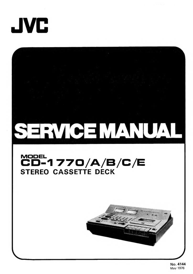
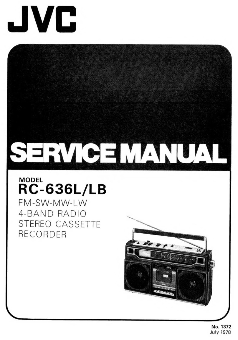
JVC RC-660 L User manual

RC-660
L/LB/LD/LE/LS
STEREO
RADIO
CASSETTE
RECORDER
No.
1533
June
1983

RC-660L/LB/LD/LE/LS
2
Contents
Page
SPeCifICAtIONS:
io
eo
25
ibe
eden
bePeae
be
tieed
ed
sed
ei
seeg
fe
idan
che
die
lad
cc
sya
ddeaelves
baud
ouveaabevnsiund
gpibesdusbe
ae
sdoikdedeecees
2
Safety
Precautions
22:5:
55.2005
6s
svecisvcesdatiedsewv
ag
eeceeve
vee
Shes
eda
vecnawueh
jauatacdeneeunsvonsphbes
ca dd
zavionegy
saelewecyedsddaibie
2
Location
of
Controls
oc.cce:
cececesees
eceudecaseesunatnete
cbs
danaeesadscuacccdncguededuetieddsnaduveedvedaverudeaevcuevecbucwbctevcueenae’
4
Location
Of
Main:
Parts
oc:
icecoccss
ocecsdastaasé
vette
Saleegod
ite
§ceeeey
as
dedneuac
une
doveee
besys
onbvecdaabeidsadevabveoxtestbadla
uae
4
Removal
of
the
Main
Parts
................cccccccceeceeeeeenccecececececcesuuesecesecseceenesaeaececsuenetsetacsauaveueetaceueeneunnes
5
How
to
Engage
Dial
Cord
.0.........ccc
cece
cceccceecceaeeeeeeece
seca
eeeeueessasecsceesecesesaueeaucecsesuausacareeueesauesaeeneneeaesss
6
Main
AdjUStMent
so.iccccesvesccscesieverescveccuectecevsteveasddcuecvhevecdsedestabecdscssavaedenauarpecegensa
das
sculi
vedas
aaede
evteusoinss
6
Standard
Schematic
Diagram
of
RC-660L/LB
(Tuner)
...............c.ccccccececceccecaucueueceeceseecaucuseecusersesusercuncens
9
Standard
Schematic
Diagram
of
RC-6G6OLD
(Tuner)
...............0.ccccccccceccecceccuceuecauccecceueauccsseuseaevevensuensvass
10
Standard
Schematic
Diagram
of
RC-66OLE
(Tuner)
.............c.0cccccccucceeueccucceccuccauecescseseseeceuseuseavensuaveuecs
11
Standard
Schematic
Diagram
of
RC-66OLS
(Tuner)
...............02cccccseceucaucccececccuccesseccacsaueusecsceaveneausuensuns
12
Standard
Schematic
Diagram
of
RC-660L/LB
(Amplifier)
.................cccccccccccecceccesecuccucecceseseucescaveusuevenans
13
Standard
Schematic
Diagram
of
RC-6GOLD/LE/LS
(Amplifier)
...............ccccccccccceccecucceccecucceceecuceccececeevanses
14
Block
Diagram
issin
ratuceans
egevaneneswkity
coSce
5s
sdeeeccceubiie
doves
dsaescelet
o
doused
bu
eebbays
eeawedeueeabeligacstovtuaseedacescasiectae
15
Tuner
P.W.
Board
Parts
and
Parts
List
.................cccccecceccccecceecucusauscuceecaeeucueeusuecueceseasauseeuecnecesanaucecaucess
16
Amplifier
P.W.
Board
Parts
and
Parts
List
.........0.......cccccsececseecceccusscuseuseuecaucusessesauccactausaeeuservensausurnvens
18
Amplifier
P.W.
Board
Parts
List
................ccccsccucccccccucccevecusuessecuccuceuenseusuesestesaecusaucuecuvensasucuacuvensansans
19
Amplifier
P.W.
Board
of
RC-6GOLD/LE/LS
0.0.00...
cec
ccc
cccccceccecuceucceccecuscusaeesuecsecusausaucuseceeueavucusauvaueens
21
Wiking:
Connections
.cciciss
cis
evescctinlen
seve
hientt
ndses
cs
goanedt
en
beugcadoun
estes
sctiasleucedaan
vow
vers
sovugiay
lecwines
beg
edeulLeereune
22
Mechanism
Component
Parts
List
.............cccccccececcecucucuseueucesuccesesesaesecececueusasatsnesesesteeecesecevnuuueuaases
23
Mechanism
Component
Parts
............cccccccecceccsecucceceececeecuceusaucuecsecueseeaeeceerectereersececeueuseecuseecetevensunnes
25
Enclosure:Assembly:
Parts...
0..2.c.cei8
voies
de
ssncesercseceyeve
slvedsueteve
dveddansvcccaseven
vies
oeshUeevinsauteedectaaugacanegiieees
26
Enclosure
Assembly
Parts
List
..............ccccccccccccceseceecueeececceseuseveuceuesecsecnessesecesesaueasaucuscseneuanvanecaess
27
PACKING
iio
dacice
cel
atceedeleean
ieaatad
ste
Da
vl
ve
w'ed
ne
uednaads
obs
eea
ened
ane
ob
obauduul
sac
oaeeantenneacene
dee
oon
aeetbad
bee
badideneiees
28
Packing
Parts:List:.
22:
co
ct
ssc
ccd
ete
atsnne
nec
evteh
od
dacuess
bz
<bbveans
ctssidevne
russes
etuven
teen
suvsceve
teat
daewiey
aw
eceepeesi
in
29
ACCOSSOMOS
iis
et
iiesctec
net
endccenict
nba
Seouaicch
ou
goed
bteede
vad
agucee
da
vapteba
nde.
Sonn
auadeecpatcacke
acta
same
Oona
duawehese
a
sebe
bus
29
Specifications
Speakers
:12
cm
(3.2
Q)x
2,
2
cmx2
Amplifier
section
Tuner
section
Power
output
:
Max.
6
W
(3
W+
3W)
at
3.2
Q
Frequency
ranges
:
FM
88
~
108
MHz
RC-660
Input
jacks
:
Mic
x
2
(0.9
mV,
200
~
2
kQ)
L/LB/LD/LS
Output
jacks
:
Headphone
x
1
65
~
73
MHz
RC-660LE
Other
terminals
:
DIN
Input
0.2
mV/kQ
MW
540~
1600
kHz
impedance
8.2
kQ
LW
150
~
350
kHz
Output
500
mV/-—
5
dBs
Swi
6~
18
MHz
impedance
10
kQ
Antennas
:
Telescopic
antenna
for
FM
&
SW
Power
supply
:
DC
9
V
(6
'‘R20”'
batteries)
Ferrite
core
antenna
for
MW
&
LW
AC
240/220/110
V
50/60
Hz
Tape
recorder
section
Power
consumption:
11
W
(RC-660LB/LD/LS)
Track
system
:
4-Track
2-Channel
stereo
10
W
(RC-660L)
Frequency
response:
80—
10,000
Hz
Dimensions
:
492(W)
x
195(H)
x
125(D)
mm
Wow
&
flutter
:
0.19%
(WRMS)
(19-3/8”
x
7-3/4”
x
5)
S/N
ratio
:
43
dB
(Normal
tape)
Weight
:
Approx.
2.7
kg
(5.9
Ibs)
Rewind
time
:
Approx.
120
sec.
(C-60
cassette)
(without
batteries)
Fast
forward
time
:
Approx.
120
sec.
(C-60
cassette)
Accessories
:
Power
cord
Heads
:
Permalloy
head
for
recording/
playback
and
erasure
Design
and
specifications
subject
to
change
without
Motor
:
Erectronic
governor
D.C.
motor
for
notice.
capstan
(No.
1533)

Safety
Precautions
AN
Safety
mark
Safety
is
very
important
with
this
unit.
When
replacing
the
parts
marked
A\
,
be
sure
to
use
only
those
designated
parts.
The
designated
resistors,
diodes,
transistors
become
hot
in
use.
When
replacing,
be
sure
to
secure
them
with
a
distance
of
more
than
5
mm
from
the
circuit
board.
In
addi-
tion,
they
are
banded
together
to
avoid
touching
other
wir-
ing,
recheck
this
point
as
well
after
repair.
The
wiring
of
the
primary
side
should
be
wound
more
than
one
and
half
times,
then
soldered.
To
protect
the
circuit
board
from
burning
while
in
use.
Power
supply
P.W.
Board
Minimum
5mm
Fuse
me
——
AC
socket
RC-660L/LB/LD/LE/LS
Minimum
Voltage
selector
Power
transformer
Fig.
1
Safety
Component
Parts
List
A
Ref.
No.
Parts
No.
Parts
Name
Remarks
Q'ty
Ref.
No.
Parts
No.
Parts
Name
Remarks
Q'ty
T401
VTP48N2-90F
Power
Transformer
|RC-660L/LE/LS/LD
1
FR301
QRH141J-100
Fusible
Resistor
102
1/4
W
1
?
VTP48N2-90FBS
RC-660LB
1
R303,304
|QRD161J-151
Carbon
Resistor
1502
1/6
W
2
—F
QMP9017-O09BS
|
Power
Cord
RC-660LB
1
R306
QRD121J-1RO
10
1/2
W
1
=
OQMP3950-183
:
RC-660L/LE/LD/LS
|
1
RC-660L/LB
$104
ae
07
R308
-1RO
12
1/2
W
1
”
RC-660L/LD/LS
Baesseenlares
ae
iz
20
AON
q
R117,217
|}QRH141J-4R7
Fusible
Resistor
4.72
1/44W
1
pecbOrr
RC-660L/LB
—
QMF51A2-R80
Fuse
T800mA
250
V
1
i
sae
QMF51A2-R80BS
“
T800mA
250V
1
R123,223
|QRH141J-4R7
4.72
2
RC-660LB
RC-660LD/LE/LS
J401
QMC0263-002U
|
AC.
Socket
1
R9,R11
QRD161J-470
Carbon
Resistor
47
1/6
W
2
‘
QMC0263-002UBS
.
RC-660LB
1
Ri0
QRD161J-101
J
100
2
1/6
W
1
MM1-6A9MK
DC
Motor
or
MM1-SA9RKF
1
C306
QET41CR-228
E.
Capacitor
2200
uF
16
V
1
D401
~
11€1
Si
Diode
4
ee
404
C308
QET41CR-228
2200
uF
16
V
1
D301
HZ6C3
Z.
Diode
1
Be
ceuhee
C102
TA7232P
integrated
Circuit
|
Power
Amp.
1.C.
1
Q302
2SC1684(R,S)
Transistor
1
eae
ese
(No.
1533)
3

RC-660L/LB/LD/LE/LS
4
Location
of
Controls
Model
RC-660LD
OW
ANOS
DK
13
14 15
Fig.
2
1.
Built-in
microphones
13.
Cassette
operation
buttons
2.
VOLUME
control
48
PAUSE
button
3.
TONE
control
M@
STOP/EJECT
button
4.
PHONES
jack
<<
FF
button
5.
Telescopic
antenna
pe
REW
button
6.
STEREO
WIDE/BEAT
CUT
switch
<)
PLAY
button
7.
MIC
jacks
O
REC
button
8.
FUNCTION
switch
14.
Cassette
holder
9.
DIN
jack
(Rec/PB)
15.
Tuning
knob
10.
FINE
TUNE
knob
16.
AC
INPUT
jack
11.
BAND
switch
17.
VOLTAGE
SELECTOR
12.
FM
MODE
switch
of
Main
Parts
Din
jack
P.W.
Board
Ass’y
(RC-660LD/LE/LS)
Location
V.
capacitor
Ferrite
core
antenna
Amplifier
P.W.
Board
Ass'y
=|
Band
select
switch
W.
speaker
——SSS
eo
Tuner
P.W.
Board
Ass'y
Mechanism
Ass‘y
Power
supply
P.W.
Board
Ass’y
Battery
contact
Fig.
3
(No.
1533)
RC-660L/LB/LD/LE/LS
Removal
of
the
Main
Parts
1.
Rear
Cabinet
1)
Remove
the
8
screws
fastening
the
rear
cabinet.
@
‘Oo
2)
Remove
the
screw
fastening
the
terescopic
antenna.
(need
not
the
rear
cabinet)
3)
Pull
out
the
receptacle
wire
on
amplifier
P.W.
Board.
2.DIN
Jack
Pull
out
the
DIN
jack
Ass’y
from
F.
cabinet.
3.
Tuner
P.W.
Board
1)
Pull
out
the
fine
tuning
knob.
2)
Remove
the
parallel
wire
from
the
tuner
P.W.
Board.
=a
Fi
8)
8)
@
y
joaiig
Knob
When
removing
the
parallel
wire,
it’s
convenient
for
connecting
then
again
to
do
marking
both
on
the
wire
side
and
socket
side.
3)
Remove
the
4
screws
3)
fastening
the
tuner
P.W.
Board.
4.
Power
supply
P.W.
Board
Assembly
Remove
2.
screws
(4)
fastening
the
power
transformer.
5.
Amplifier
P.W.
Board
Assembly
1)
Pull
out
2
knobs
6)
(Volume
and
Tone).
2)
Remove
3
screws
;
3)
Remove
3
connectors
(@)
b
and
(Cc).
6.
Mechanism
Assembl
Remove
4
screws
()
fastening
the
mechanism
assembly.
7.
Speaker
(See
Fig.
6)
Fig.
6
1)
Remove
4
screws
(8)
fastening
the
speaker
of
Left
side.
(R
ch
speaker)
2)
Remove
4
screws
(9)
fastening
the
speaker
of
Right
side.
(L
ch
speaker)
Note:
Mechanism
parts
section
is
the
same
as
those
of
the
service
manual
RC-770L/LB/LD/LS
(No.
1531)
Please
refer
to
the
service
manual
of
RC-770L/LB/LD/LS
(No.
1531)
(No.
1533)
5

RC-660L/LB/LD/LE/LS
How
to
Engage
Dial
Cord
1.
Turn
the
dial
drum
fully
clockwise
(to
the
highest
fre-
quency).
2.
Use
Kevlar
Cord
(620
mm
long
and
0.4
mm
diameter).
3.
Instail
the
string
in
the
sequence
of
the
numbers.
Nw
@
Wind
on
the
shaft
Three
turns
Fig.
7
Main
Adjustment
[1]
Adjustment
of
Cassette
Mechanism
Check
the
following
items
after
cassette
mechanism
parts
are
replaced.
Item
Requirements
Test
equipment
Test
tape
Rated
voltage:
9.0
VDC
1.
Source
voltage
Motor
operating
voltage
Regulated
power
supply
——
4
range:
7—10V
DC
4.8
cm/sec
(3,000
Hz)
2.
Tapespeed
|
_......
2,060
~
3,090
Hz
Frequency
counter
(digital
counter)
|
VTT-656A
Deviation
within
60
Hz
3.
Wow
&
flutter
Less
than
0.35%
(RMS)
Wow
meter
VTT-656A
PLAY
35—75g.cm
During
FF
and
rewind,
the
idlers,
reels
and
flywheel
should
not
slip
=o
4.
Take-up
torque
FF
60—200
g.cm
against
each
other
when
the
reels
REW
60—200
g.cm
are
locked.
5.
Current
ie
RAS
Cs
Saeed
a
C-60
(take-up
torque
consumption
FF
250
mA
or
less
DC
ammeter
should
be
normal
when
(of
motor
alone)
|
Rew
250
mA
or
less
tape
is
used.)
Tension
gauge
Pull
the
pinch
roller
perpendicularly
6.
Pinch
roller
375~475g
and
read
the
gauge
pressure
when
the
pinch
roller
just
stops.
ies
7.
Head
position
During
PLAY
(RECORD)
the
dimensional
requirements
operation
and
extent
move-
ment
perpendicularly
and
read
the
gauge
when
the
mechanism
just
Auto
stop.
40~70g
|
Cassette
Guide
during
PLAY
given
here
must
be
met,
and
|
Any
cassette
tape
and
RECORD
the
heads
must
not
contact
the
cassette
case.
~70
:
#0
q
Tension
gauge
pull
8.
Auto-stop
Within
3.5~5.5mm
the
Auto
stop
lever
Any
cassette
tape
6
(No.
1533)

RC-660L/LB/LD/LE/LS
[I]
Electrical
Circuit
Adjustments
Electrical
Adjustment
of
Location
BEAT
CUT
(Amplifier)
F2s3
CN10
SLIT
PATTERN
LE
ee
SLIT
to
Rle
PATTERN
C4
O
BIAS
FREQ
L301
TP
Te2
VR30!
©
onet
(GND)
OS
He)
ats
CURRENT
$102
Fig.
8
Model
RC-660
L/LB/LD/LE/LS
|
Cassette
section
Source
voltage
DC:
9V,
Load
O
dBs
mW
(0.775
V)/3.2
2
AC:
240/220/110
V
Step
Item
Adjustment
method
1
Measurement
Confirmation
Standard
blank
tape
for
measurement
will
be
the
following:
Method
Norma!
tape
LNC-60.
2
Speed,
Wow
&
Flutter
When
the
wow
&
flutter
is
measured
by
the
test
tape
VTT-656
(3,000
Hz)
or
another
tape
of
the
same
kind,
the
value
of
the
wow
&
flutter
should
be
within
___%.
The
speed
value
should
be
within
+15%
to
—15%
3020
Hz.
Measurement
is
RMS.
——EEe
3
Recording/Playback
Frequency]
Signal
of
—
20
dB
against
the
standard
input
and
the
value
when
1,000
Hz
and
the
frequen-
Characteristics
cies
listed
below
are
recorded
and
played
back.
Normal
tape
1000
H2/125
Hz:
O
dB
+4
dB
1000
Hz/6.3
kHz:
+1dB+
dB
4
Recording/Playback
Distortion
|
Record
and
playback
the
fixed
input
signals
of
1,000
Hz
and
measure
the
distortion
rate.
The
Rate
Measurement
value
should
be
as
follows:
Normal
tape
within
8%.
5
Playback
Output
Using
the
test
tape
VTT-663
(1,000
Hz)
or
another
tape
of
the
same
kind,
the
playback
out-
Measurement
put
value
should
be
as
follows:
(9
V
impressed
to
CN-104)
10%
>
2100
mW
(2.59
V/3.2
Q)
(7
V
measured
to
CN-102)
Max.
output>
2500
mW
(2.83
V/3.2
Q)
6
Playback
Frequency
Using
the
test
tape
VTT-673N
or
another
tape
of
the
same
kind,
each
value
is
as
follows
when
Characteristics
1,000
Hz
is
changed
to
O
dB:
1000
Hz/125
Hz:
O
dB+3
cB
1000
Hz/
8
Hz:
0
dB+3
dB
4
7
Playback
Level
Confirmation
Playback
the
test
tape
and
confirm
that
the
level
difference
between
the
C-R
is
within
3
dB
when
an
output
of
0
dBs/3.2
2
is
obtained
with
CN-102.
lf
it
does
not
fit
within
the
standards,
cut
out
the
lightning
pattern
and
fit
it
into
the
pattern.
Pattern
L
(A)
Slit
Pattern
L
Short
—
L
channel
approximately
2
dB
up.
Pattern
R
(B)
Slit
Pattern
R
Short
—
R
channel
approximately
2
dB
up.
8
Wide
Circuit
Operation
When
you
playback
the
signals
of
the
left
and
right
channels,
the
signals
should
be
played
Confirmation
back from
the
opposite
channel
from
in
the
WIDE
position.
(Example:
When
the
right
channel
signal
is
received
with
a
stereo
modulation
with
an
output
of
60
dB
and
30%
modulation
of
FM
1
kHz:
BEAT
CUT
1-2
[
BEAT
CUT3/WIDE
Rch
0
dB
|
+5
dB
Lch
|
—2
dB
|
cz
Note
:
If
some
do
not
fit
in
within
the
standards
during
recording/playback,
frequency
characteristics
and
recording/playback
distor-
tion
rate
measurement,
fit
in
adjusting
the
UR-BO.
Bias
electric
current
increase
—
high
range
rises
during
recording/playback
Distortion
rate
worsens.
Bias
electric
current
decreases
—
high
range
lowers
during
recording/playback
Distortion
rate
improves
(No.
1533)
7

RC-660L/LB/LD/LE/LS
{II]
Tuner
Alignment
The
model
RC-660L/LB/LD/LE/LS
is
the
same
as
the
model
RC-770L/LB/LD/LS
(No.
1531)
except
the
FM
RF
Alignment.
Please
refer
to
the
service
manual
for
the
model
RC-770L/LB/LD/LS
(No.
1531)
FM
RF
Alignment:
RC-660L/LB/LS
eo
pine
pubes
eee
be
Frequency
of
SSG
Variable
Capacitor
Position
peace
1
87.5
MHz
Max.
capacity
L2
2
109.0
MHz
Min.
capacity
TC-2
3
EM
Dummy
Adjust
the
above
aligning
position
(L2
&
TC-2)
repeatedly
so
that
the
Antenna
tuner
can
be
received
above
frequency
range
(band
width).
i
a
90
MHz
to
be
received
90
MHz
L1
5
106
MHz
to
be
received
106
MHz
TC-1
6
Adjust
the
above
aligning
position
(L4
&
TC-1)
repeatedly
so
that
the
tuner
can
be
obtained
the
best
sensitivity.
RC-660LD
|
‘|
switch
Epa
poe
ay
eee
Be
Frequency
of
SSG
Variable
Capacitor
Position
|
Boones
1
|
87.5
+0.05
MHz
Max.
capacity
|
i
2
108.3+0.07
MHz
Min.
capacity
|
Te-2
3
EM
Dummy
Ajust
the
above
aligning
position
(L2
&
TC-2)
repeatedly
so
that
the
Antenna
tuner
can
be
received
above
frequency
range
(band
width).
4
90
MHz
to
be
received
90
MHz
L1
5
106
MHz
I
to
be
received
106
MHz
TC-1
6
Adjust
the
above
aligning
position
(L1
&
TC-1)
repeatedly
so
that
the
tuner
can
be
obtained
the
best
sensitivity.
RC-660LE
i
=
lacus.
Paar
|
Benen
ana
peice
ean
be
Frequency
of
SSG
|
Variable
Capacitor
Position
poe
1
64
MHz
Max.
capacity
L2
2
74
MHz
|
Min.
capacity
TC-2
3
EM
Dummy
Adjust
the
above
aligning
position
(L2
&
TC-2)
repeatedly
so
that
the
Antenna
tuner
can
be
received
above
frequency
range
(band
width).
4
65
MHz
|
to
be
received
65
MHz
L1
5
73
MHz
|
to
be
received
73
MHz
t
TC-1
6
Adjust
the
above
aligning
position
(L1
&
TC-1)
repeatedly
so
that
the
tuner
can
be
obtained
the
best
sensitivity.
Part
Arrangement
of
Alignment
MONO=*5T
mf
(SW_ANT)
i
EON
cama
Te
iTC-5
my
TP1
TP2
ae
FM
ANT)
a
EMiSTe
SW.
se
ag:
LI
al
=
rea
BH
yc
|@
(uw
osc?
(mw
OSC)
©
@
TP3
VRi
\QKHz
leg,
QRee
eo
=|
roa
hea[
[ics
=
2
CEE.
_
Ae?
2
ADJ
8
(No.
1533)
LPF
|
t
LJ
7
jg)
«
is
.2
[Ohm
ose:
mw
i
2
©
(eM
vet)
©
TP6
CE)
>
CNI
Fig.
9

RC-660L/LB/LD/LE/LS
Standard
Schematic
Diagram
of
RC-660L/LB
(Tuner)
2
|
BP
ll
5
i
6
|
7
8 9
10
FM
FRONT
END
1C
1)
AN7213
BPF.
VBP4M3B-001
co--—-
25C1359(C)
or
2SC2561(C)
R6
100k
42
49
49
O
52
514
Q)
MPX
1C
3)
AN7410N
VQZ0018-002
19kHz
Adj
QVZ
3512
-103
>
a
S
50 “7
5
assi20)
:
g
~
026
Q2
os
3
2$C828(Q,R)
To
Amp
7
=
ve
ls!
=
0
=|
24
bub)
|
L
4
I
4
i
ai
S
uo)
|
GND
1
|
02
es
G
7
|
=
PTO
|
R
a)
‘a
hoe
5
Ho
S
SHO
148
5.5
ee
z
a
0
ow
VMW1068A
O
—
ame
eee
ees
ees
ee
eee
eee
eee
oe
4
S1-1---
-8
Q@SS8401-101
Blue
line
shows
the
signal
at
FM.
|
a
Red
line
shows
the
signal
at
AM
(MW/LW/SW).
De
apy
eh
ae
ee
cage
Say
ee
gees
a
ee
ee
eed
cafe
eet
eo
ee
NOTE.
1.S1-1~S1-8(
BAND
SELECT
SWITCH)
IS
FM
eres
A
Parts
are
safety
assurance
parts
MONAURAL-
STEREO
SWITCH)
IS
STEREO
POSITION
(QSS1
201-02!
:
‘
2.52
(MO
When
replacing
those
parts,
make
sure
to
use
the
specified
one.
3,
VOLTAGES
ARE
MEASURED
WITH
NO
SIGNAL
USING
EiECTRONIC
VOLT
METER
AT
FM
POSITION,
(
)VALUES
AT
AM
(LW/MW/SW)
POSITION.
4—
VALUES
AT
EM
POSITION
WHEN
60dByV
STEREO
SIGNAL
1S
SUPPLIED
TO
ANTENNA
TERMINAL
(TP1,2).
5.
LAST
NO.
R34,C61,L9
.Q2
BLANK
NO.
R14,20,25,26,
30,31
C4,
13,41,44,47,
55
Fig.
10
6
THE
RATING
OF
ALL
RESISTOR
IS
1/6W
(No.
1533)
9

RC-660L/LB/LD/LE/LS
Standard
Schematic
Diagram
of
RC-660LD
tunes
1
2 3
4
|
5
|
6
7
8
9
|
10
A
C48
tu
SOV
|
FM
FRONT
END
—
IC
1
|
_
l
B
xs
|
=
|
5
Oo
3
|
faa)
ie)
2
>
aa
|
ze
218
C
s
r
5
Te
|
R21
470
‘al
ae
|
O+-—
NWN
eve
°
no
|
f
is
:
Socom
Gee
Is
co
isl
o
‘Ga
VOTIFI2-104
—
rer
ry).
Sor
1)
(0
aS
12
ral
Q
=|
54
5
:
S'
5
|
(54)
=|
i
:
o
jf
43
oe
:
ti
aS
mle
D
a:
!
TPL
ol
4)
2
5!
Ss
=
a
Os
page
a
a
i
ae
<I
!
ON
|
o
|
E
|
R13
68
pp
RIS.
68
|
c25
(MW_
OSC)
|
360P)
53
|
|
O
O
:
5
93
|S!
|
L
=
ua
O
|
O
Sle
ate:
are
0$58401-101
oe
aes
|
|
Blue
line
shows
the
signal
at
FM.
F
Ne
pt
tenes
cw
es
ee
ee ee
eee
ee
ee
ee
ee
_]|
ae
aa
Red
line
shows
the
signal
at
AM
(MW/LW/SW).
NOTE:
1.
$1-1~S1-8
(BAND
SELECT
SWITCH)
IS
FM
POSITION
(QSS8401-101)
Ps
ne
2.
$2
(MONAURAL-STEREO
SWITCH)
IS
STEREO
POSITION
(QSS1201-026)
Parts
are
safety
assurance
parts.
os
3.
VOLTAGES
ARE
MEASURED
WITH
NO
SIGNAL
USING
ELECTRONIC
VOLT
METER
AT
FM
POSITION.
When
replacing
those
parts,
make
sure
to
use
the
specified
one.
(
)
VALUES
AT
AM
(LW/MW/SW)
POSITION.
4.
|
|
|
VALUES
AT FM
POSITION
WHEN
60
dBuV
STEREO
SIGNAL
IS
SUPPLIED
TO
ANTENNA
TERMINAL
(TP1,
2).
5.
LAST
NO.
R34,
C64,
L9,
Q2
BLANK
NO.
R11,
2,
3, 6,
7,
20, 25,
30,
31
5.
BLANK
NO.
C7,
8,
23,
41,
44, 47,
55
Fig.
11
6.
THE
RATING
OF
ALL
RESISTOR
IS
1/6
W.
(No.
1533)
10

Standard
Schematic
Diagram
of
RC-660LE
tuner)
RC-660L/LB/LD/LE/LS
5
6
7
8
9
10
A
|
a
FM
FRONT
END
|
IC
1
TA7358P
|
Q1
2$C1359(C)
or
25C2561K(C)
D2
1S553T
pees
|
IC
3.
AN7410N
[MPX]
|
1.7]
|
II
7
B
cs
OBOE
Pei
0471!
P
aetcs2
’
ae
er
|
f!
:
a
AIL
6)
Z
hes
1
Lig
yone
LS
|
VCFZL3
B-301
x
SOV
csi
0.022)
|
TiS
iti!
215
x2
ss
=@
TP7
047%
SOV
@
—
;
fu
i
"
i)
&
S
i
S
|
oO}
C
(tea
pao
|
eet
pees
Zla_
6
§
Y
oP)
235
o
|
eee
S|
HOS
2
yl
e593
28
a
at
a
a
5
}
oO]
0.47
SOV
oa
S
a
x
Sj
S
Cc
|
[paces
5
is
a
!
aa
2
tk
gt
Re
ST.
IND
;
FM
_-o
ST
Que
0
|MONOO+]
©
os
OT
Ss
LN
28RPL
oO
7
#29
|s2
:
=
02
|
i
O
a
R
assi201
ee
i
5.0
19
“7
e
|
!
80)
|=
“MW
oO
25C828(Q,R)
2
SS
wv
so
[th
ewe
2
MONO*ST.
!
=
50)
ls
L__
4
O10)
)
L
i
1
=
aI
so
|<
a
|
<|
oe
PO
|
GND
D
|
ale
B3,
ols
S
Eu)
SM,
ANT)
o>
-
S
|
le
o
QR7002-302
fo
#240
|4+6
55
je
2
=
C46
0.022p
45)
=
iy
2
+y
10u
16V
mM
wy
0
a
47
VMW1068A
6.21
6
ae
nw
pt
ee
ne
ore
0.4
F
5.2
:
=
|
E
Reo
O
|
oe
ee
-
R13,
68
©
RIS
68
5
So
‘
C2
©
(MW
OSC)
C26
)
1S0P
=
360P
P0039.
Se
g
|
a
Pte
t
9
apo
tt
eae?
8
‘
Att
6
SiS!
Ve
i316)
or
*
oS
igs=|
"|
|
Po
Ls
5
a]
Pt
|
dO
N
o”
|
Oo
FAS
O
|
d
*
=
no
|
:
we)
oO
ara
oO
fa
a
L§
L7
LB
©
—
vomu0t-s01
@
vor7002-302
~
ieee
NIB
i
TCS
~8
Ol]
|
a55840!-10
|
F
L_
<i)
NOTE:
1.
S1-1~S1-8
(BAND
SELECT
SWITCH)
IS
FM
POSITION
(QSS8401-101)
2.
$2
(MONAURAL-STEREO
SWITCH)
IS
STEREO
POSITION
(QSS1201-026)
3.
VOLTAGES
ARE
MEASURED
WITH
NO
SIGNAL
USING
ELECTRONIC
VOLT
METER
AT
FM
POSITION.
(
)
VALUES
AT
AM
(LW/MW/SW)
POSITION.
4.
|
]
VALUES
AT
FM
POSITION
WHEN
60
dBuV
STEREO
SIGNAL
IS
SUPPLIED
TO
ANTENNA
TERMINAL
(TP
1).
5.
LAST
NO.
R34,
C64,
LY,
Q2
BLANK
NO.
R11,
2,
3,
20,
25,
30,
31
C23,
41,
44,
47,
55,
63
6.
THE
RATING
OF
ALL
RESISTOR
IS
1/6
W.
Fig.
12
(No.
1533)
11

RC-660L/LB/LD/LE/LS
Standard
Schematic
Diagram
of
RC-660LS
une:
1
2 3
4
5
6
7
8 9
10
A
APF.
ROD
VBP1U3B-001
C48
ty
SOV
|
ANT
jose
ian
FM
FRONT
END
SRB:
@
IC
1
[FM_iF
|
=
!
Q1
2SC1359(C)
or
28C2561(C)
|
=
!
D2
1S553T-
R6
100k
l
poate
ro
ox
3
CF1
—CF2
a
|
|
2
I
tes
|
}
5%
|
|S
a
Z
aAG
|
le
|
>
|
oO
|
J
fo
1
|S
TP2
/
8
|
|=
|
o
£62
001,
2
1
2c)
§
i
|
N
“a
——-}+-—73
EARS
|
5
sad
Fo
ee
5
2
——
2
|
&
ST.
INO
>
LN28RPL
a
Loos
TY
eg
Ly
Tre
O00
re.
LO
——O
0000
oO
O
1]
Lol
TS
kal
0am
00
L5
c26
(SW
OSC
Cn
G26,
LW
OSC)
1.
$1-1~S1-8
(BAND
SELECT
SWITCH)
IS
FM
POSITION
(QSS8401-101)
2.
S2
(MONAURAL-STEREO
SWITCH)
IS
STEREO
POSITION
(QSS1201-026)
3.
VOLTAGES
ARE
MEASURED
WITH
NO
SIGNAL
USING
ELECTRONIC
VOLT
METER
AT
FM
POSITION.
( )
VALUES
AT
AM
(LW/MW/SW)
POSITION.
4.0'[
]
VALUES
AT
FM
POSITION
WHEN
60
dBuV
STEREO
SIGNAL
!S
SUPPLIED
TO
ANTENNA
TERMINAL
(TP1).
5.
LAST
NO.
BLANK
NO.
R34,
C65,
L9,
Q2
R1,
2, 3,
20, 25,
30,
31
C23,
41,
44,
47,
55,
63,
64
6.
THE
RATING
OF
ALL
RESISTOR
IS
1/6
W.
(No.
1533)
12
J
E>
©
no
Qssi201
SAG
=a
“
“
e
50
~026
V
MWi068B
ete
|
s+
|
2
#3
3
50
epee
eres
|
|
-
sy
29,
[MONO<-=ST
|
:
A
|
©
:
Z
mi
P|
S|
30)
PC
|
GND
0
ec!
N
WG
84)
Y
R
er
Sy)
(SW__
ANT)
ae
G1
25)
VQR7002-302
.
+B
55

RC-660L/LB/LD/LE/LS
Stnadard
Schematic
Diagram
of
RC-660L/LB
tanniitien
a
fe
2
|
3
4
5
|
6
|
7
|
8
|
9
10
R107
12k
R109
6.8k
Volume
Control
Lch
Gio,
R747
PHONES
J301
s
Tweeter
QVP0001-473S
Rigg,
77
EFB-S77D43
L101
(|
Wooter
3.29
»
|
I
8
HSA1299-01D
oy
s
HSA
1299
-
01D
3
Woofer
3.20
>
|
Tweeter
EFB-S77D4)
pe
=
Eom
MMI-6A
9MK
Mod!
N
-O16
AA
oo=
or
QMS3501-01
AE
Hie
eae
+
MMI
SASRKF-S
VMW1070-
OOXC
au
/6W__1/6W
ee
r+]
Ea
R303
R304]
|
al
+
b
S
TAPE
|
ill
ee
delet
ae
i
|
re
O
a
=
ee
eT
cee
eo
6)
O
ECM
nl
paoi~4oe
LN
CNI04
VMME62N-031
|
11E1-TB2
or
1SR35-100
VMW
1070
-00XD
|
|
[ee
|
+
rf
|
Er)
=
p———,
UM-1x6
9V
|
‘pommeaae
ane
VMW
1070
ECM
|
~
OOXE
VMME
62N-03]
|
To
Tuner
|
8
ae
EF
S401
|
o—
at)
a
—
TO
SOCKET
!
au
iu
|
anco2e3400zuBS
L.
Ls
pany
ia
ea
a
cc
ee
oem
mes
Sn
ee
ae
ees
SEE
pee
pl
LAST
NO.
BLANK
NO.
NOTE
1
SWITCH
S10I~1---8
FUNCTION
:
TAPE
POSITION-----
QSL8210-
104
C8,
218
2
SWITCH
S102-1--12,
REC
/PLAY
:
PLAY
POSITION----
QSSC201-106
C320
3
SWITCH
S103-1---4
BEATCUT
WIDE
:
BEATCUT
]
POSITION
----
QS$4301-034
C404
R13,
213,114,
214
4
SWITCH
$104
VOLTAGE
SELECT:
220V
POSITION
-----
@S$2325-108
ae
ate
R307
,
308
,
314
5
SWITCH
$105
MOTOR
:
ON
POSITION
-------------
LSA
1120C0
IT
6
VOLTAGES
ARE
MEASURED
WITH
NO
SIGNAL
USING
ELECTRIC
VOLT
METER.
(REC(
)),
REFERENCE
POINT
IS
CNI04
7
ATL
,
VTP48N2-
90FBS
—=
VTP48N2-90F
:
wracclaie
Blue
line
shows
the
signal
at
playback.
QMC0263
-
002UBS
—=
QMC0263-
002U
ain
caine
Red
line
shows
the
signal
at
recording.
QSS2325-107BS
—e
05S
2325-107
——+——_
+
B
circuit
man
Parts
are
safety
assurance
parts.
When
replacing
those
parts,
make
sure
to
use
the
specified
one.
Fig.
14
(No.
1533)
13

RC-660L/LB/LD/LE/LS
Standard
Schematic
Diagram
of
RC-66O0LD/LE/LS
anpiitien
1
athe.
2
|
3
4
|
5
|
6
|
7
E
—
8
[9
|
10
—i
«=e ems
eseesm
cee
cee ice
cee
oeeese
ieee
===
ames
«sm
iam
es
~=9s==e
e==e
===
esses
eme=e
-«eses=
es=
i-«—s===
-—=s==
~s=ep
e—==e
«==
4
VRIO1
201
~~
VRIO2-
202
|
MQVNSA2D-024M
QVN5A2A-
054M
TONE
VOLUME.
Q102,
2501302
(R,S,.T)
|
K)
MIC
MUTE
R121
1.2k
OV
'¢
PCS
aaenee
8
ov.
Ny
3301
o
QMS6312-012
E
©
SAF
;
Ho}
Fl
_
6
x
ne
QO
=
VMW3198
=
|
2
Tweeter
10
WwW
EFB-S77D41
—
ad
MIC
a
Pe
Woofer
3.2.0
OMS
3507-016
“A
HSA1299-
01D
z
wt
i
F
C
Ve)
Woofer
321
2
HSA1299-01D
LI0}
osas
R105
|
Se
Tweeter
18K
is)
251684
(R,S)
2SD1302(R,S,T
EFB-S77D41
4
=
cio
zor
cies'o0@
7»
@)
8
DIN
AMP
MIC
MUTE
$102-2
S102-3)
MMI-
6A9MK
000
|
or
PER
MMI-5A9SRKF
=5
D
Mie
$105
J20)
|
QMS350i-O16
Ec)
oI
vMWwig70-00
qy
3)
VMME
62N-032
SI
Z
|
=)
[|
R28
47k
C121,
330P
VQH1009-
026
o
einccolsof
31s
1
1301
<5
E
=
Boe
ae
COcHyoow
OTS
ah
eX
b
RNS
22k
EC
5
@]
I
los
8
+
eq
|
8S
aS
BIAS
Ec
|
L
|
[=e
|
nawmazo-ooalp
v
C30
co
58V
VMME62N-031
|
Q302
dl
Eb
©
)
=
2506841RSNS
Soe
Cy
om
ne
io)
4
wre
epic
2SCKEARS)
[S=
REGULATOR
3
|
eee
BN
ersesstaay
REC.
2
38
Ni
OMFS
1A2-R80
66kHz(BEAT
CUT?)
|[BIAS
OSC]
2.18
tar
he
LN
550uUA/CH
9
2
2
Lo
G
|
a
VMW1070-00XB
VTP48N2-90F
0S$2325-108
J
NOTE
1}
SWITCH
$101—1---8
FUNCTION
:
TAPE
POSITION
----
QSL8210—104
LAST
NO.
€121,221,
321
2
SWITCH
$102-1---12
REC/PLAY
:
PLAY
POSITION----QSS4301-034
R128,
228,503
,
513
3
SWITCH
S$103-1---4
BEATCUT
WIDE
:
BEATCWT
1
POSITION
----
QSS4301-034
:
4
SWITCH
=
S104
VOLTAGE
SELECT
:
220V
POSITION----@QSS2325-108
;
Blue
line
shows
the
signal
at
playback.
5
SWITCH
$105
MOTOR
:
ON
POSITION
--------------
LSAI120COIT
Red
line
shows
the
signal
at
recording.
6
SWITCH
S501-1---4
DIN
.
OFF
POSITION----QSP4210-061
—+——-
+B
circuit
7
VOLTAGES
ARE
MEASURED
WITH
NO
SIGNAL
USING
ELECTRIC
VOLT
METAR.
uN
Parts
are
safety
assurance
parts.
(RECI
))
(REC&
DIN
OFF
1)
REFERENCE
POINT
IS
CNI04.
When
replacing
those
parts,
make
sure
to
use
the
specified
one.
Fig.
15
(No.
1533)
14

RC-660L/LB/LD/LE/LS
Block
Diagram
Tuner
section
is
the
same
as
those
of
the
service
manual
RC-7
70L/LB/LD/LS
(No.
1351).
Please
refer
to
the
service
manual
of
RC-770L/LB/LD/LS
(No.
1351).
Playback
system
PRE
AMP
POWER
AMP
IC
101
IC
102
aie
TA7232P
Y
slo
5
os
-6
+4
Sl]
2-10
x
|
+e
|
H.
phones
62
419
62
aap
"Jack
From
Tuner
VR
102
J301
ae
oo)
Volum
Control
DIN
Ae
baad
Tone
r
3
Woofer
6
Control
:
Speaker
Tweeter
Speaker
DIN
Jack
LON
(LD/LE/LS
only)
Fig.
16
CR,
Record
system
PRE
AMP
Fig.
17
(No.
1533)
15

RC-660L/LB/LD/LE/LS
Tuner
P.W.
Board
Parts
and
Parts
List
RC-660L/LB/LS
ea
|
=
on
oe
ieee
eS
aR
“oy,
nrc
Seen
ae
sees
a
re
oa
me
ee
RC-660L/LB/LS
Parts
List
Ref.
No.
Parts
No.
Parts
Name
Remarks
Q'ty
VMW
1068-003A
Tuner
P.W.
Board
A’ssy
vc-1~4
QAP1224-520V
|
V.
Capacitor
TC-1~4
TC5~8
QAT2002-001_
|
T.
Capacitor
VvC5
QAT5001-004
|M.V.
Capacitor
VR1
QVZ3512-103
|V.
Resistor
L1
VQF1B12-007
|RF
Coil
(FM)
L2
VQF1B10-001
|OSC
Coil
,
L5
VQR7002-302_
|
RF
Coil
(SW3)
L6
VQL7T19-301
|
OSC
Coil
(LW)
L7
VQM7U01
:
(MW)
L8
VQR7002-302
_
(SW)
LQ
V03047-21
Coil
L3,4
VQB012B-314
|
Bar
Ant.
Ass’y
T1
VQT7F12-104
|
IFT
T2
fe
-104
‘
T3
VQT7A11-203
ss
CF1,2
VCF2L3B-301
C.
Filter
CFT
VOT7A21-102
|C.F.T.
Ref.
No.
Parts
No.
Parts
Name
Remarks
Q'ty
BPF
VBP4M3B-001_
|Band
Pass
Filter
LPF1,2
VQZ0018-002
|
Low
Pass
Filter
1C1
AN7213
LLC.
IC2
AN7222N
”
IC3
AN7410N
a
Qi
2SC1359(C)TA
|
Si.
Transistor
Q2
2SC828(0,R)TA
i
D1
MA165
Si.
Diode
D2
1S553T
Vari
Cap
$1-1~8
QSS8401-101
|
Slide
Switch
Sz
QSS1201-026
.
R1,10
QRD161J-101
|C.
Resistor
100
Q
1/6W
|
2
R2
~
-271
a
2702
7
1
R3
:
-393
th
39
kQ
1
R4
*
-184
"
ie
80
kQ
i
1
RS,19,21
;
-471
iy
47002
:
3
R6,7
is
-104
.
100
kQ
id
2
R8,9,11
.
-470
.
472
-
4
17
16
(No.
1533)

RC-660L/LB/LD/LE/LS
Ref.
No.
Parts
No.
Parts
Name
Remarks
Q'ty
RC-660LD/LE
R12
QRD161J-224
|C.
Resistor
2202
1/6W!]
14
R13,15
"——
.680
4
68
0
(
2
R16,28
"102
1kQ
2
R18,22
"332
a
13.3
kQ
ft
2
“
R23,32,33
"222
s
2.2
kQ
3
f'
i
|
R24
"
.273
y
27
ko
| |
R27
"103
"
10
kQ
a
:
R29
"183
y
18
ka
Zo
|
R34
"2153
-
15 kQ
C1
QCS11HJ-100
|C.
Capacitor
|
”
0.022
uF
50V
C2
QCF11HP-223
|
C3
QCS11HJ-240
i
24
pF
C5
QCTOSCH-150
”
15
pF
|
cé
QCTO5UJ-5RO
fi
5
pF
C7
QCTO5UJ-5RO
”
5
pF
i
c8
QCF11HP-103
i
0.01
pF
i
cg
QCTO5CH-150
i
15pF
«16
V
C10
QCY11HK-472
Z
0.0047uF
50V
C11
QCF11HP-223
.
0.022
uF
‘
C12
"——
-103
f
0.01
uF
'
C14
QCS11HJ-470
is
47
pF
‘
:
C15
ig
-390
i’
39
pF
2
:
C16
i
-120
a
12
pF
.
|
C17
ts
-100
p
10
pF
;
C18
we
-100
7
1
pF
:
C19
[
-470
7
47
pF
C20
QCS11HJ-270
.
27
pF
7
C21
QCTO5WK-100
Me
10
pF
“
C22
QCTO5WK-8RO
id
8
pF
C23
QCS11HJ-150
.
15
pF
C24
QFP32AJ-150
é
150
pF
10V
C25
"——
-361
’
360
pF
i
C26
a
-392
i
0.0039
uF”
C27
QCS11HJ-150
|C.
Capacitor
15
pF
50
V
C28
QCF11HP-223
.
0.022
»F
”
QCS11HJ-7RO
.
7
pF
QCC11EM-223
0.022
pF
25
QCF11HP-103
$
0.01
uF
50
QET41AR-476
|
E.
Capacitor
47
uF
QEN41EM-475
QET41HR-105
QCF11HP-223
N.P.
Capacitor
4.7
pF
E.
Capacitor
C.
Capacitor
"223
QCC11EM-223
C38
QCS11HJ-121
Fig.
19
C39
QCC11EM-223
c40
QET41ER-106
RC-660LD/LE/LS
Tuner
P.W.
Board
Parts
List
ee
eee
Refer
to
RC-660LD/LS/LE
Parts
List
when
checking
the
other
parts.
es
mal
cee
Ref.
No.
Parts
No.
Parts
Name
Remarks
Ref.
No.
Parts
No.
Parts
Name
Remarks
Q'ty
41HR-105
c49
QCC11EM-473
|
C.
Capacitor
u1
VOF1B12-004
RF
Coil
(FM)
RC-660LE
QRD161J-392
C.
Resistor
3.9k2
1/6W/
1
C50
QCF11HP-223
"—
.001
4
(FM)
"—
.220
.
220
?
1
C51
QET41HR-474
|E.
Capacitor
RC-660LD/LS
QCS11HJ-220
C.
Capacitor
22
pF
50
V
1
C52
rer
-
0.47
uF”
L2
V03105-030
OSC
Coil
(FM)
RC-660LE
’
-150
7d
15
pF
i
1
C53
"474
-
0.47
uF"
-029
re
-220
22
pF
7
1
C54
OFP42AJ-471
|P.P.
Capacitor
|470pF
10V|
2
:
°
r
‘
ee
i
L5
QR7002-302
_—_—|RF
Coil
c4
OCY41HK-472
0.047
pF
1
C56,57
QCC11EM-153
|C.
Capacitor
2
:
C5
OQCTO5CH-100
”
”
i
BPF
VBP1U3B-001
B.P.
Filter
-
10
pF
1
C58,59
QET41HR-104
|E.
Capacitor
0.1
pF
50V
|
2
C6
”
200
” ”
eee
Se =:
VBP4M3B-001
RC-660LD/LS
:
20
pF
1
c60
"2105
‘
1
aE
"14
IC1
TA7358P
CT
"—
-8RO
.
8
pF
ij
1
cé1
QETC1AM-477
i
470uF
10V]
1
=
cg
QCTO5UJ-6RO
7
6
pF
1
C63
QCTOSCH-3RO
‘“
1
=
Omitting
.
cN1
£04365-004
_|
Connector
1
R2
=
}
Paits
ae
oes
hee
03
:
Jo.01
uF”
1
VMZ0015-001
|
Post
Pin
4
R3
=
11HJ-200
20
pF
1
R4
QRD161J-334
330kQ
1/6W
C62,63
-103
:
a
"
2
ae
ree
4709
”
C64
QCTO5CH-3RO
3
pF
?
1
1
(No.
1533)
17

RC-660L/LB/LD/LE/LS
Amplifier
P.W.
Board
Parts
and
Parts
List
of
RC-660L/LB
1
2
3 4
—
5
6
7
8 9
10
2
7
rf
:
1
ae
E
J)
ee.
Fig.
20
+B
(No.
1533)
18

Amplifier
P.W.
Board
Parts
List
A\
parts
are
safety
assurance
parts.
When
replacing
those
parts,
make
sure
to
use
the
specified
one.
RC-660L/LB/LD/LE/LS
}
aN
|
Ref.
No.
Parts
No.
Parts
Name
Remarks
Q'ty
[VMW1070-O00XA
Amplifier
P.W.
Board
Ass’y]
$101-1~8
QSL8210-104
Lever
Switch
Radio/Tape
1
$102-1~12
QSSC201-106
Slide
Switch
Play/Rec.
1
$103
QSS4301-034
7
Beatcut/Wide
1
VR101,201
QVN5A2D-024M
V.
Resistor
Tone
20
kQ
1
VR102,202
QVN5A2A-054M
"
Volume
50
kQ
1
VR301
QVZ3512-201
7
Bias
OSC
1
J101,201
QMS3501-016
Jack
EXT
MIC
2
J301
QMS6312-012
Headphone
Jack
Phones
1
1¢101
M51544L
1.C
Pre
Amp.
1
1C102
TA7232P
1.C
Power
Amp.
1
Q301
2SC1684
(R,S)
Transistor
1
Q302
2SC1684
(R,S)
:
1
=
VYH5368-002
Radiation
1
D101,201
MA165
Si.
Diode
2
D301
HZ6C3
Zener
Diode
1
L101,201
VQP0001-473
Inductor
2
L301
VQH1009-026
OSC
Coil
1
C101,201
QCY41HK-152
C.
Capacitor
1500
pF
50
V
2
C102,202
QCS11HJ-121
if
120
pF
wt
2
C103,203
QCY41HK-272
#
2700
pF
if
2
C104,204
QFN41HJ-683
M.
Capacitor
0.068
uF
©
2
C105,205
QET41CR-226
E.
Capacitor
22
uF
16V
2
C106,206
QET41AR-107
"
100
pF
10V
2
C107,207
QET41HR-105
is
1
uF
50
V
2
C108,208
QCC11EM-223
C.
Capacitor
0.022
pF
25V
2
C109,209
QET41HR-104
E.
Capacitor
0.1
wF
50
V
2
C110,210
QCC11EM-154
C.
Capacitor
0.15
pF
10V
2
C111,211
QET41AR-107
—.
Capacitor
100
pF
As
2
C112,212
QET41ER-106
id
10
pF
25V
2
C113,213
QCS11HJ-471
C.
Capacitor
470
pF
50
V
2
C114,214
QET41AR-477
E.
Capacitor
10
V
2
C115,215
QET41HR-335
e
50
V
2
C116,216
QCS11HJ-331
.
Capacitor
50
V
2
C117,217
QCC11EM-473
25
Vv
2
C118,119
QCC11EM-104
7
4
;
1
1
1
1
QET41HR-475
.
Capacitor
C302
QET41AR-476
i
47
uF
10
V
C303
QETC1AM-337
f
330
pF
‘
QETC1CM-227
“
220
uF
16V
QET41ER-475
e
4.7
uF
25V
A
QET41CR-228
x
2200
pF
16
V
QET41HR-105
1
pF
50
V
1
C308
QET41CR-108
E.
Capacitor
1000
pF
16V
1
C309
QCC11EM-103
C.
Capacitor
0.01
pF
25V
1
C310
QCY41HK-682
7
0.0068
uF
50
V
1
C311
QFN41HK-152
M.
Capacitor
0.0015
uF
ss
1
C312
QCY41HK-222
C.
Capacitor
0.0022
uF
”
1
C313
QCC11EM-223
e
0.022
uF
25
V
1
C314
QET41AR-476
E.
Capacitor
47
uF
10V
1
C315
&
-336
7
33
uF
.
1
C316
OQCF11HP-223
C.
Capacitor
0.022
yF
50
V
1
C317
QET41AR-477
E.
Capacitor
470
uF
10
V
1
C318~320
QCS11HJ-151
C.
Capacitor
150
pF
50
V
3
-
QRD161J-xxx
Carbon
Resistor
See
Schematic
Diagram
1/6
W
48
R117,217
QRH141J-4R7
C.
Resistor
4.79
1/4
2
R302
QRD121J-106
7
10
MQ
1/2
W
1
A\
|
R306
“_-1RO
10
1
A,
|
FR301
QRH141J-100
Fusible
Resistor
100
1/4W
1
CN102
QMV5004-004
Connector
1
CN101
i
-005
3
1
CN103
QMV5005-005
.
1
CN104
QMV5004-002
a
1
[VMW1070-00XC/D
E.C.
MIC
P.W.
Board
Ass’y]
|
VMME62N-031
E.C.
MIC
2
[VMW1070-00XB
Power
Supply
P.W.
Board
Ass’y]
A
|
1401
VTP48N2-S0FBS
Power
Transformer
RC-660LB
1
A
"
”
—
-90OF
RC-660L/LD/LE/LS
1
A
_
QMF51A2-R80BS
Fuse
RC-660LB
T800
mA
1
A
=
ue
-R80
4
RC-660L/LD/LE/LS
T800
mA
1
A44594-001
Fuse
Clip
2
A
|
D401
~404
11E1
Si.
Diode
4
C401
~
404
QCF11HP-223
C.
Capacitor
4
J401
QMC0263-002UBS
AC
Socket
RC-660LB
1
e
-002U
‘s
RC-660L/LD/LE/LS
1
AV
|
$104
QSS2325-107BS
Slide
Switch
RC-660LB
1
A}
”
“107
RC-660L/LD/LE/LS
1
VND4003-038
Fuse
Label
1
(No.
1533)
19

RC-660L/LB/LD/LE/LS
20
RC-660OLD/LE
Amp.
P.W.
Board
Parts
List
Refer
to
RC-660L/LB
Parts
List
when
checking
the
other
parts.
Ay
parts
are
safety
assurance
parts.
When
replacing
those
parts,
make
sure
to
use
the
specified
one.
A|
Ref.
No.
Parts
No.
Parts
Name
Remarks
Q'ty;
|
A
|
Ref.
No.
Parts
No.
Parts
Name
Remarks
Q'ty
Q101,201
2SC1684(R,S)
Transistor
2
C301
QET41HR-475
E.
Capacitor
4.7
pF
50V
1
Q102,202
2SD1302(R,S,T}
a
2
C305
QET41AR-107
i
100
»F
10V
1
C101,201
QCY41HK-821
C.
Capacitor
820
pF
50V
2
C306
OQET41ER-475
ue
4.7
uF
25V
1
C104,204
QET41HR-105
E.
Capacitor
1
pF
4
2
C308
QET41CR-228
"
2200
pF
16
V
1
C105,205
OFN41HJ-683
M.
Capacitor
0.068
pF
2
C309
QCS11HJ-151
C.
Capacitor
150
pF
50V
1
C106,206
OQET41ER-226
E.
Capacitor
22
uF
25V
2
C310
QET41CR-477
E.
Capacitor
470
nF
16V
1
107,207
|QET41AR-107
e
100
nF
10V
|
2
C311
QCC11EM-103
|C.
Capacitor
|0.01
pF
25V
]
1
C108,208
QET41HR-104
0.1
uF
50
V
2
C312
OQFN41HJ-152
M.
Capacitor
0.0015pF
50
V
1
C109,209
‘
-105
1
pF
2
C313
QCY41HK-682
C.
Capacitor
O.0068yF
”
1
C110,210
JQER41HR-335
£
3.3
pF
50
V
2
C314
iM
-272
“
0.0027
pF
”
i
C111,211
QCC11EM-223
C.
Capacitor
0.022
pF
25
V
2
C315
QCC11EM-223
”
0.022
pF
25
V
1
112,212
|QCY41HK-681
,
680
pF
50V
|
2
C316
QET41AR-107
_|E.
Capacitor
[100
nF
10V
|
1
C114,214
QCC11EM-154
i
0.15pF
25V
2
C317
QCF11HP-223
C.
Capacitor
0.022
nF
50
V
1
C115,215
-473
0.047
uF
2
C318
QETC1AM-477
”
470
nF
10V
|
1
C116,216
-104
.
0.1
BF
2
C319,320
QCS11HJ-151
150
pF
50V
2
C117,217
QETC1AM-477
E.
Capacitor
470
nF
10V
2:
C321
QET41ER-106
E.
Capacitor
10
pF
25V
1
C118,218
QET41AR-107
100
pF
2
—
QRD161J-xxx
C.
Resistor
1/6
W
|
54
C119,219
QET41ER-106
10
wF
25V
1
R123,223
QRH141J-4R7
Fusible
Resistor
{4.7
Q
V/4W]
2
C120,220
-335
33
uF
2
L302
7T41572-001
Inductor
1
C121,221
QCS11HJ-331
330
pF
50V
2
D502,512
MA165
Si.
Diode
2
RC-660LD/LE/LS
DIN
Jack
P.W.
Board
Parts
List
Ref.
No.
Parts
No.
Parts
Name
Remarks
Q'ty
VMW3
198-002
DIN
Jack
P.W.
Board
Ass‘y
J501
QMC9014-006
|DIN
Jack
Ass’y
1
$501-1-4
|QSP4210-061
|Push
Switch
1
D501,511
|MA165
Si.
Diode
2
R501,511
|QRD144J-155S
|C.
Resistor
1.5
MQ
1/4
W
z
R502,512
-155S
.
1.5
MQ
2
R503,513
-222S
2.2
kQ
2
VYH5388-001
|DIN
Bracket
1
SPSP2606Z
Screw
2
(No.
1533)
DIN
P.W.
Board
This manual suits for next models
4
Table of contents
Other JVC Cassette Player manuals