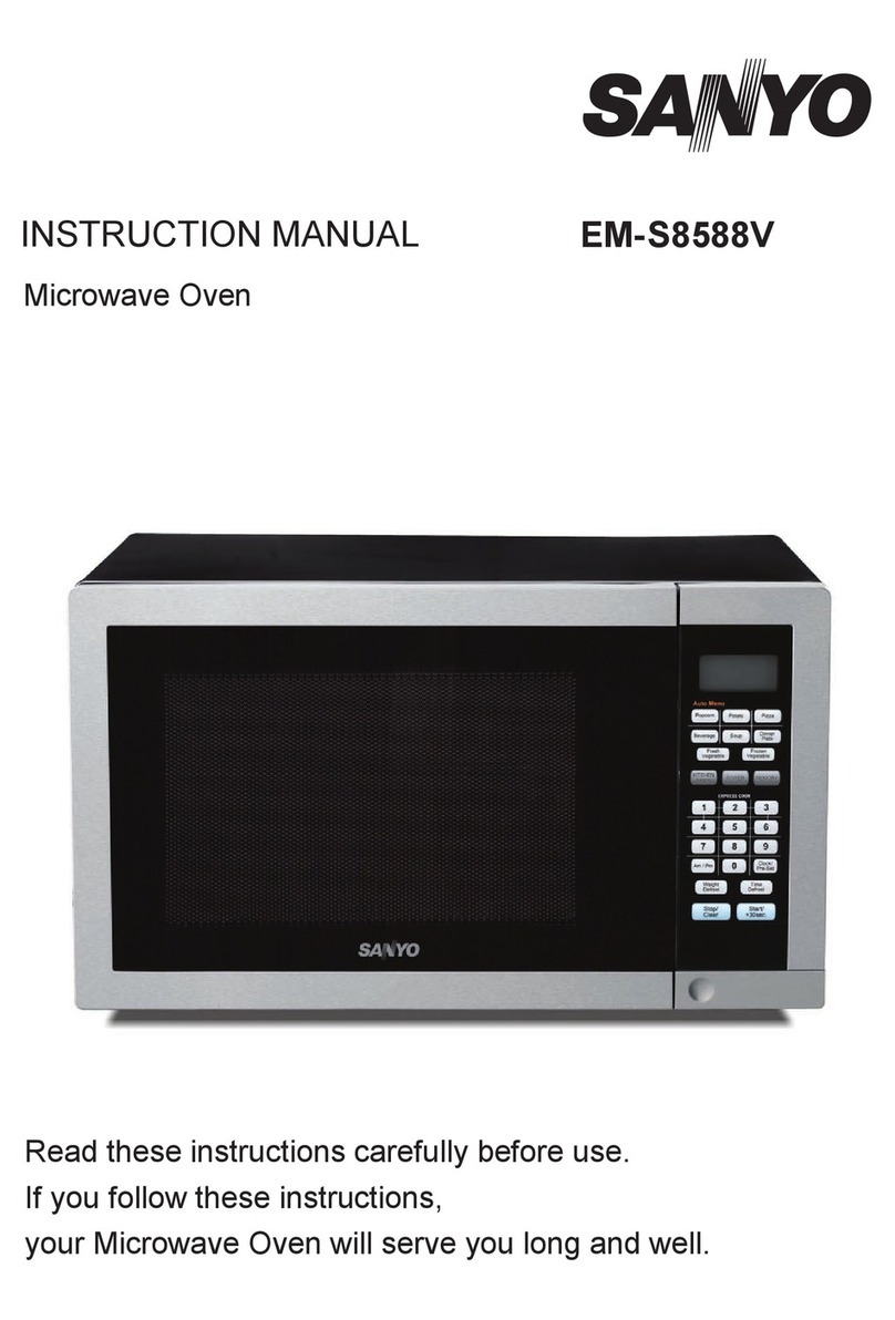
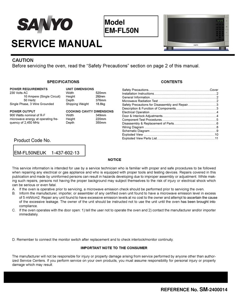
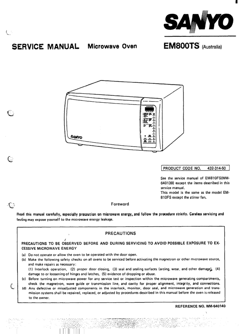
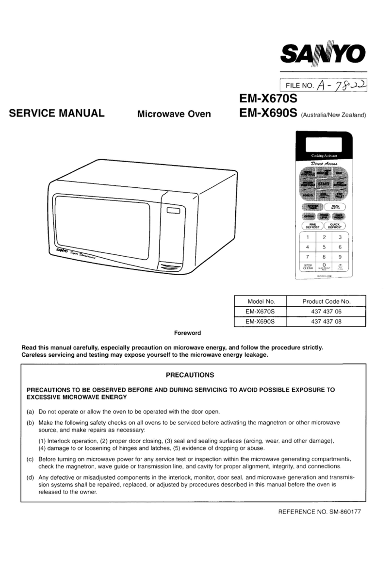
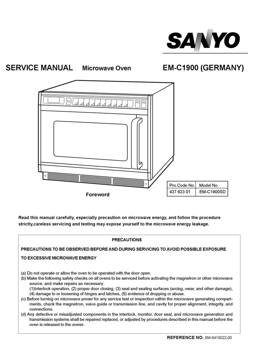
Sanyo EM-C1800MK User manual

PRECAUTIONS
PRECAUTIONSTO BE OBSERVED BEFORE AND DURING
SERVICING
TO
AVOID POSSIBLE EXPOSURETO
EXCESSIVE MICROWAVE ENERGY
(a) Do not operate or allow the oven to be operated with the door open.
(b) Make the following safety checks on all ovens to be serviced before activating the magnetron or other
microwave source, and make repairs as necessary:
(1)Interlock operation, (2) proper door closing, (3) seal and sealing surfaces (arcing, wear, and other
damage), (4) damage to or loosening of hinges and latches, (5) evidence of dropping or abuse.
(c) Before turning on microwave power for any service test or inspection within the microwave generating
compartments, check the magnetron, wave guide or transmission line, and cavity for proper alignment,
integrity, and connections.
(d) Any defective or misadjusted components in the interlock, monitor, door seal, and microwave generation
and transmission systems shall be repaired replaced, or adjusted by procedures described in this manual
before the oven is released to the owner.
SERVICE MANUAL Microwave Oven EM-C1800MK(Germany)
EM-C1800MK(U.K)
REFERENCE NO.
SM-640177
Model No Pro.Code No
EM-C1800MKSD 437 477 00
EM-C1800MKUK 437 477 01
Foreword
Read this manual carefully, especially precaution on microwave energy, and follow the procedure strictly,
careless servicing and testing may expose yourself to the microwave energy leakage.

- 1 -
- TABLE OF CONTENTS -
Adjustment Procedures.............................................1
Specifications............................................................2
Power output Measurement ......................................2
Precautions and Repair Service Tips .......................2
Circuit Diagram .........................................................3
Test Procedures and Troubleshooting...............4 •`9
Disassembly Instructions .............................. 10•`12
Exploded View and Parts List ........................ 13•`20
Overall Circuit Diagram.................................21•`23
1. ADJUSTMENT PROCEDURES
TO AVOID POSSIBLE EXPOSURETO MICROWAVE
ENERGY LEAKAGE, THE FOLLOWING ADJUST-
MENTS OFTHE INTERLOCK SWITCHES SHOULD
BE MADE ONLY BY AUTHORIZED SERVICE PER-
SONNEL.
PRIMARY INTERLOCK SWITCH,INTERLOCK MONI-
TOR SWITCH AND DOOR SENSING SWITCH AD-
JUSTMENT
(Figure 1)
(1) Loosen 2 screws securing the lever stopper.
(2) Adjust the lever stopper position so that it is pushed
up and pull backward until there is about zero gap
between the latch lever and the switch body on the
door primary interlock switch and the at the same
time there is about zero gap between latch lever
and the switch body on the door sensing switch
when the door latch is securely locked.
(3) Tighten the lever stopper screws securely.
(4) Make sure the interlock monitor switch closes af-
ter the primary interlock switch opens the door is
opened very slowly, according to “CHECKOUT
PROCEDURE FOR SWITCHES” on page 6.
(5) Make sure the interlock monitor switch opens be-
fore the primary interlock switch closes when the
door is closed very slowly, according to CHECK-
OUT PROCEDURE FOR SWITCHES” on page 7.
CAUTION
MICROWAVE RADIATION
PERSONNEL SHOULD NOT BE EXPLOSEDTOTHE
MICROWAVE ENERGYWHICH MAY RADIATE FROM
THE MAGNETRON OR OTHER MICROWAVE GENE-
RATING DEVICE IF IT IS IMPROPERLY USE OR
CONNECTED. ALL INPUT MICROWAVE CONNEC-
TIONS,WAVEGUIDE, FLANGES, AND GASKETS
MUST BE SECURE. NEVER OPERATETHE DEVICE
WITHOUT A MICROWAVE ENERGY ABSORBING
LOAD ATTACHED. NEVER LOOK INTO AN OPEN
WAVEGUIDE OR ANTENNA WHILETHE DEVICE IS
ENERGIZED.
(6) Make sure the microwave energy leakage should
be no greater than 5 mW/cm2to allow to measure-
ment uncertainty when measured with a detector.
(All service adjustments must be made for mini-
mum microwave energy leakage readings.)
NOTE: If the interlock monitor circuit operates and at
the same time the fuse blows with the door
opened, be sure to replace the control circuit
board because relay 3 and 4 on the control cir-
cuit board, the door sensing switch and the elec-
tric circuit related on the door sensing switch,
which act as Secondary Interlock switch.
Interlock monitor
switch
Lever stopper
Latch Lever
Primary Interlock
switch
Latch Lever
Door sensing
switch
Figure 1
Screws

- 2 -
2.SPECIFICATIONS
Microwave output ................1,800W to 180W
Frequency ...........................2,450MHz
Power supply.......................230V, 50Hz
Rated current ......................13 Amp.
Safety Device ......................
Thermal limitter (Magnetron)
150 °C Open
80 °C Close
Thermistor (Magnetron) ..200 °C Open
108 °C Close
Thermistor(Duct).............120 °C Open
Fuse (Cartridge Type) .....250V 10A
Micro switch, Relay
Primary interlock Switch
Interlock monitor Switch
Door sensing Switch and
Relay RL-3 and 4
Max. input time....................Electronic Digital, up to
Manual
10min.
Memory 30min.
Overall Dimensions........422(W)x540(D)x335(H) mm
Oven cavity size ............330(W)x330(D)x230(H) mm
Effective Capacity of Oven Cavity ...............19.1
liters
Net weight ...........................32Kg
3. POWER OUTPUT MEASUREMENT
(1) Prepare 1000+5g tap water.
(2) Adjust water temperature to 10•}2 °C .
(3) Pour water into a container made of borosilicate
Glass, 190mm outer diameter cylinder, maximum
3mm thickness.
Note :Use the container kept on the room tem-
perature.
(4) place the container on the center of oven cavity.
(5) Set the heating time for 27 seconds and rating
full power and then start oven.
(6) Take the container out immediately when heat-
ing time is up.
(7) Stir water for making even water temperature in
the container.
(8) Measure water temperature.
Water temperature rise shall be 8 to 12 °C.
4. PRECATIONS AND REPAIR SERVICETIPS
PRELIMINARY
A. SINCE NEALY 4,000VOLTS EXISTS IN SOME
CIRCUITS OF THIS MICROWAVE OVEN, RE-
PAIRS SHOULD BE CARRIED OUT WITH
GREAT CARE.
B.TO AVOID POSSIBLE EXPOSURETO MICRO-
WAVE ENERGY LEAKAGE,THE FOLLOWING
PRECATIONS MUST BETAKEN BEFORE SER-
VICING.
(1) Before the power is applied.
(a) Open and close door several times to make
sure the door interlock switch and interlock
monitor switch operation properly.
(Listen for the clicking sound from switches.)
make sure the interlock monitor switch is
closed after the latch interlock switch is open
when the door is opened. (See pages 1 and 8)
(b) Make sure the perforated screen and the choke
dielectric of the door are correctly mounted.
(2) After the power is applied.
(a) Open and close the door to see if the interlock
mechanism operates properly.
(b) Check microwave energy leakage with a leak-
age detector and confirm the energy leakage
is below 5mW/c‡u.
(3) Do not operate the unit until it is completely
repaired if any of the following conditions exists.
(a) Door is not closed firmly against the
cavity front.
(b) The hinge is broken.
(c) The choke dielectric or the door seal is dam-
aged.
(d) The door is bent or warped, or there is any
other visible damage to the oven that may
cause microwave energy leakage.
Note: Always keep the seal clean.
(e) Make sure that there are no defective parts in
the interlock mechanism.
(f) Make sure that there are no defective parts in
the microwave generating and transmission as-
sembly.
(especially wave guide)
(4) Following items should be checked after the unit
is repaired.
(a) The interlock monitor switch is connected cor-
rectly and firmly.
(b) The magnetron gasket on the magnetron is
properly positioned.
(c) Waveguide and oven cavity are intact. (No
leakage of microwave energy).
(d)The door can be properly closed and the safety
switches work properly.
(e) The oven must be stopped when the door is
opened or the time is up.
The oven must not be operated with any of the above
components removed or bypassed.
HINT FOR LAMP-CHANGE
Before removing the cabinet, pull out the main-plug.
If you want to check the new lamp with the open
Cabinet, take care of the following safety-cautions:
Do not touch live parts.The lamp holder is not con-
nected to the earth protection lead by a metric
screws.
- 3 -

- 4 -
6.TEST PROCEDURES ANDTROUBLESHOOTING
CAUTION
-DISCONNECTTHE POWER SUPPLY CORD FROMTHE
WAL OUTLET WHENEVER REMOVING THE CABINET
FROMTHE UNIT.
PROCEED WITH TESTS ONLY AFTER DISCHARGING
THE HIGH VOLTAGE CAPACITOR AND REMOVINGTHE
LEAD WIRES ON THE PRIMARY WINDING OFTHE HIGH
VOLTAGETRANSFOREMER. (SEE FIGURE 3)
A.TEST PROCEDURES
1) Check for resistance: Across the filament ter-
minal of the magnetron with an ohm - meter on
Rx1 scale.
2) Check for resistance: Between each filament
terminal of the magnetron and the chassis
ground with an ohm-meter on highest scale.
COMPONENT
MAGNETRON
HIGH-VOLTAGE
TRANSFORMER
1) Measure the resistance:
With an ohm-meter on R x1 scale.
a. Primary winding;
b. Filament winding;
c. Secondary winding;
2) Measure the resistance:
with an ohm-meter on highest scale.
a. Primary winding to ground;
b. Filament winding to ground;
CHECKOUTPROCEDURE RESULT
Normalreading:
Less than 1 ohm.
Normalreading:
Infinite ohms.
Normal reading:
Approximately 1.0 ohms
Less than 1 ohm.
Approximately 60 ohms
Normal reading:
Infinite ohms.
Infinite ohms.
Note: Remove varnish of measured point.
Primary
windings Secondary
Windings
Filament
Windings

- 5 -
Measurethe resistance:Acrosstwoterminalswith
an ohm-meter on highest scale.
COMPONENT
HIGH-VOLTAGE
CAPACITOR
Including
bleeder
resistor
HIGH-VOLTAGE
DIODE
Measurethe resistance:Acrosstwoterminalswith
an ohm-meter on highest scale.
CHECKOUTPROCEDURE RESULT
Normalreading:
Momentarilyindicatesseveralohms,and
gradually to 10 meg-ohms.
Abnormalreading:
Indicates continuity or 10 meg-ohms
from the beginning.
Normalreading:
Indicate about the middle position in one
direct (forward) and infinite ohms in the
reverse direction, using meter with a 9-
volt battery. NOTE
-Somedigitalmetermayshowovereven
in a forward direction because low mea-
suring voltage of meter does not allow
the meter to pass through the high volt-
age diode.
Abnormalreading:
Indicates continuity or infinite ohms in
both directions.
FUSE DIODE
Measurethe resistance:Acrosstwoterminalswith
an ohm-meter on highest scale. Normalreading:
Indicate infinite ohms in both directions.
Abnormalreading:
Indicates continuity in both directions or
continuity in one direction and infinite ohms
in reversed direction.

- 6 -
Check each voltage at connector S104 and S105
afterremovingeachconnector(female)frompower
circuit board.
Pin No.3 (Ground) and 4,5, 1,2 at S105.
Pin No.1 and 2 at S104.
CAUTION:
Proceed with the test only after removing the
wire leads from the primary winding of high
voltage transformer for your safety.
Test procedures:
a) Make sure that the power supply cord is not
plugged in.
b) Remove the connector S104 and S105 from
the power circuit board.
c) Plug the power supply cord.
d) And then, measure each voltage.
COMPONENT
POWER
P.C.B
CONTROL
P.C.B
Measure the voltage:Between test pointsTP-1,
TP-2 ,TP-3 and ground (See figure 14 on page
23)
Note
- Proceed with the check of the control P.C.B to
see if any one of the measured values is differ-
ent from the specified values.
CHECKOUTPROCEDURE RESULT
Normalreading:
Connection
Pin No., Voltage(V)
S105
#3 to #4 DC 12
#3 to #5 DC 16
#3 to #1 DC 30
#3 to #2 DC 35
S104
#1 to #2 AC 2.4
Test point
TP, Voltage(V)
TP-1 DC - 5
TP-2 DC - 12
TP-3 DC - 16
TP-4 DC - 35

- 7 -

- 8 -
Power is applied with
normal voltage
Timer is set
Touch Select key No display
cooking time Power circuit board
(See page 6) Voltage
incorrect Replace
Control circuit
board
(See page 6)
Voltage
incorrect Replace
Primary
Interlock switch
(See page 7)
No continuity Replace
Thermal protector No continuity Replace
Cooking opera-
tion will not start
Door sensing
switch
(See page 7) No continuity Replace
Control circuit
board
(See page 6)
Voltage
incorrect Replace
Control
circuit board
(See page 6)
Voltage
incorrect Replace
H.V Transformer
(See page 4) Resistance
incorrect Replace
H.V Capacitor
(See page 5) Resistance
incorrect Replace
Magnetron
(See page 4) Resistance
incorrect Replace
Monitor switch
(See page 7) Contact on
No continuity Replaceor
Adjust
Blower motor Shorted Replace
Step-down
Transformer Shorted Replace
Oven dose not
heat up
Fuse(10A) blows
off immediately
B.TROUBLESHOOTING
CONDITION TROUBLE CHECK RESULT REMEDY
Connection of
S110 to S107 Poor Contact Reconnect

- 9 -
Thermistor for duct of cavity top is operated by
over heating of 120
DISPLAY
E-21
E-31 Thermistor for lower magnetron or duct is
shorted.
Trouble Situation
Buzzer will continuously beep tone. Blower
motor will stop immediately.Then oven will
stop heating.
Blower motor will stop immediately.Then
oven will stop heating.
E-32 Thermistor for lower magnetron or duct is dis-
connected or removed from connector socket. Oven will stop heating.
Blower motor will be operated.
C. ERROR INDICATION
This model has some self diagnosis functions.
Display shows "E" depending on the trouble.
CONDITION TROUBLE CHECK RESULT REMEDY
Shorted Replace
H.VTransformer
Shorted Replace
H.V Capacitor
Shorted Replace
Magnetron
Shorted Replace
H.V Diode
Shorted Replace
Fuse Diode
Poor
oscillation Replace
Magnetron
Lowmicrowave
output
Rotation
stop Repairor
replace
Rotation of top or
bottom anttena
Unevenheating
U-10 Thermistor for Magnetron is operated by over
heating of 200 Buzzer will continuously beep tone.
Blower motor will stop immediately.
Then oven will stop heating.
U-50 The purpose of this function is to prevent opera-
tion when there is no food in the oven Open and close the door, and then touch
the key before 1 minute passes
°C
°C

- 10 -
7. DISASSEMBLY INSTRUCTIONS
- OVEN MUST BE DISCONNECTED FROM ELEC-
TRICAL OUTLETWHEN MAKING REPLACEMENTS,
REPAIRS, ADJUSTMENT AND CONTINUITY
CHECKS BEFORE PROCEEDING WITH ANY RE-
PAIR WORK AFTER DISCONNECTING, WAIT AT
LEAST 1 MINUTE, UNTILTHE CAPACITOR INTHE
HIGHVOLTAGE AREA HAS FULLY DISCHARGED.
A. REMOVING PRIMARY INTERLOCK SWITCH
(See Figure 1 on page 1)
(1) Disconnect all lead wires from the primary in-
terlock switch.
(2) Remove 2 screws securing the lever stopper.
(3) Remove 1 screw securing the switches.Then
pull out the switches.
(4) Make necessary adjustment, and make micro-
wave energy leakage check according to “1. AD-
JUSTMENT PROCEDURE FOR SWITCHES” an
page 1, after it is replaced with new one, and
check proper operation of it according to
“CHECKOUT PROCEDURE FOR SWITCHES”
on page 7.
B.REMOVING INTERLOCK MONITOR AND DOOR
SENSING SWITCH
(See Figure on page 1)
(1) Disconnect all lead wires from the interlock moni-
tor switch and door sensing switch.
(2) Remove 1 screw securing the these switches.
Then pull out the switches.
(3) Make necessary adjustments or replacement of
switch by the reversing step (2) and check mi-
crowave energy leakage according to “1. AD-
JUSTMENT PROCEDURE FOR SWITCHES” on
page 1, after it is replaced with new one, and
check proper operation of it according to
“CHECKOUT PROCEDURE FOR SWITCHES”
on page 7.
WHEN REPLACING ANY DOOR MICROSWITCH,
REPLACEWITHTHE SAMETYPE SWITCH SPECI-
FIED ON THE PARTS LIST.
C. REMOVING FUSE
Remove the 10A fuse with screwdriver.
NOTES
- When replacing the 10A fuse, be sure to use an exact
repair part.
- If the 10A fuse blows immediately, check the primary
interlock switch, the relay 3 and 4 (on the control cir-
cuit board) and the interlock monitor switch according
to “CHECKOUT PROCEDURE FOR SWITCHES” on
page 8. and make sure to check the microwave en-
ergy leakage according to “1.ADJUSTMENT PROCE-
DURE FOR SWITCHES” on page 1, when the primary
interlock switch, the relay 3 and 4 or the interlock moni-
tor switch is adjusted or replaced.
- If the primary interlock switch, the relay 3 and 4 or
the interlock monitor switch operate properly, deter-
mine which of the followings is defective : control cir-
cuit board, blower motor, gear motor, high voltage trans-
former, high voltage capacitor, high voltage diode or
magnetron.
- If the high voltage diode is defective replace not only
the high voltage diode but also the fuse diode.
D. REMOVING DISPLAY CIRCUIT BOARD
(1) Disconnect all lead wires of the Control panel
from the Control PCB and Power PCB.
(2) Remove 4 screws securing the Control panel
Ass’y to the oven cavity.
(3) Push up and pull out the Control panel Ass’y.
(4) Remove 4 screws securing the Display PCB.
(5) Take out the Display PCB and push up the lever
end of the plastic fastener and remove the FPC
connector from the connector socket S101.
CAUTION:
When replacing new Display PCB please take big
care that all 4 LED heads shoul dexacty be in-
serted into the square holes of control frame all
at once.Never force to push any LED lead in the
PCB.
E. REMOVING MAGNETRONS
(1) Remove 2 screws securing the thermal limitter .
(2) Disconnect 2 lead wires from the magnetron
terminals by removing 2 connectors.
(3) Remove thermistor (lower magnetron) by
pulling horizontally.
(4) Remove 4 hex nuts (upper magnetron) or 2 hex
nuts (lower magnetron)securing to the
waveguide.
(5) Remove lower magnetron.
(6) Take out the magnetronVERY CAREFULLY.
NOTES
- When removing the magnetron, make sure that its
dome does not hit any adjacent parts, or it may be
damaged.
- When replacing the magnetron, be sure to install the
magnetron gasket in the correct position and be sure
that the gasket is in good condition.
- After replacing the magnetron, check for microwave
make sure the microwave energy leakage is below the
limit of the regulation (5mW/cm2).

- 11 -
F. CHANGING POWERSUPPLY CORD
(See exploded view on page 15)
(1) Unfasten 1 screw for earth and pull out 2 wires
of power cord from terminal plate.
(2) Remove1 screw for bottom bracket of cord
bushing.
(3) install the new power supply cord with reverse
procedure of above (1) to (2).
WARNING:
For the changing the power supply cord, never
use other than following.
Key No.Order No. Parts Name
4 617 208 1076 Power cord Ass’y(Germany)
5 617 196 9184 Power cord Ass’y(UK)
6 617 078 3132 Cord bush (UK)
7 617 140 1332 Cord bush (Germany)
39 617 125 3832 Bottom bracket (UK)
40 617 140 1349 Bottom bracket (Germany)
G. REMOVING CERAMIC TRAY ASS’Y
(See Fig.11 )
(1) Take off the cabinet.
(2) Put (insert) a screwdriver in the 9 mm diameter
hole locating at lower hinge of left side of the
oven cavity.And push the tray up with the screw-
driver.
(3) Open the door and take out the tray very care-
fully.
H.REMOVING DOOR
Remove 2 hex nuts securing the upper hinge,
remove 3 hex nuts securing the lower hinge and
remove1 special screwsecuring the door arm
(located at the bottom of the door sash).
NOTES
- After replacing the door, be sure to check that the
primary interlock switch, the door sensing switch
and the interlock monitor swich operate normally.
(See pages 1 and 7)
- After replacing the door, check for microwave ene-
rgy leakage with a leakage detector. Microwave
energy leakage must be below the limit of
5mW/c‡u.
I.HOWTO RESETTHE MEMORY OF ACCUMU-
LATIVE COOKINGTIME
1. Push the keys step by step as follows,
Turn the Timer Knob to left until display shows“0”.
Touch START key first and also touch POWER
SELLECTION key (1800W) until display changes.
The display will show accumulative cooking time
in the display window.
2.Then push the POWER SELLECTION key(1800W)
during cooking time appear in the display.
3. Push the POWER SELLECTION key(1800W) for
4 seconds continuously.
Accumulative cooking time will be cleared.
J.CAUTION FOR CUSTOMER ON OPENING
AND CLOSING DOOR
When the Microwave oven is in operation, should
the customer open the door slightly and close, the
breaker of the house will occasionally be cut off.
It is necessary to explain to the customer not to
exercise such matter.
When the Door is opened slightly between 2 or 3
mm distance, primary interlock switch turn OFF,
and operation stops.
However door sensing switch will remain ON, and
if door is closed, primary interlock switch activates
and operation resumes immediately.
At such time microwave oven will start any time.
Therefore a big In-rush currnet flows, and thus
Breaker will be cut off.
Figure 11
Screw driver
Door
Hole

- 12 -

- 13 -
8. EXPLODEDVIEW AND PARTS LIST
Main body Parts-1
Parts marked with this sign have special
Characterstics important for microwave leakage.
When replacing any of these parts use only
Manufacturers specified parts.

- 14 -
Parts marked with this sign have special
Characterstics important for microwave leakage.
When replacing any of these parts use only
Manufacturers specified parts.
Parts marked with this sign are supplied with
high voltage exceeding 250V

- 15 -

- 16 -
Main body Parts-2
Parts marked with this sign are supplied with
high voltage exceeding 250V
Parts marked with this sign have special
Characterstics important for microwave leakage.
When replacing any of these parts use only
Manufacturers specified parts.

- 17 -
Parts marked with this sign are supplied with
high voltage exceeding 250V
Parts marked with this sign have special
Characterstics important for microwave leakage.
When replacing any of these parts use only
Manufacturers specified parts.

- 18 -

- 19 -
Table of contents
Other Sanyo Microwave Oven manuals

Sanyo
Sanyo EM?S667S User manual

Sanyo
Sanyo EMS-8500S User manual

Sanyo
Sanyo EM-P672WS User manual

Sanyo
Sanyo EM-CD2900UK User manual

Sanyo
Sanyo EM-SL40S User manual

Sanyo
Sanyo EM-S156AW User manual

Sanyo
Sanyo EM-SL50GRILL User manual

Sanyo
Sanyo EM-V5404SW - Full Size Microwave Oven User manual

Sanyo
Sanyo EM-G5595S User manual

Sanyo
Sanyo EM-S7720V User manual

Sanyo
Sanyo EM-X400 User manual

Sanyo
Sanyo EM-X475S User manual

Sanyo
Sanyo EM-S5002W Use and care manual

Sanyo
Sanyo EM-Z2000S Use and care manual

Sanyo
Sanyo EM-C8787B User manual

Sanyo
Sanyo EM-S357BW User manual

Sanyo
Sanyo EM-C1900 User manual

Sanyo
Sanyo EM-S2298V User manual

Sanyo
Sanyo EM-V860 User manual

Sanyo
Sanyo EM-C8787V User manual