manuals.online logo
Brands
  1. Home
  2. •
  3. Brands
  4. •
  5. Sanyo
  6. •
  7. Microwave Oven
  8. •
  9. Sanyo EM-C950 User manual

Sanyo EM-C950 User manual

SERVICE MANUAL Microwave Oven EM-C950 (~’ 0,
Foreword
Read this manual carefully, especially precaution on microwave energy, and follow the procedure strictly. Careless servicing and
testing may expose yourself to the microwave energy leakage.
PRECAUTIONS
PRECAUTIONS TO BE OBSERVED BEFORE AND DURING SERVICING TO AVOID POSSIBLE EXPOSURE TO EX-
CESSIVE MICROWAVE ENERGY
(a) Do not operate or allow the oven to be operated with the door open.
(b) Make the followlng safetv checks on all ovens to be serviced before activating the magnetron or other microwave source,
and make repairs as necessary:
(1) Interlock operation, (2) proper door closlnq, (31 seal and sealing surfaces (arcing, wear, and other damage), (4)
damage to or loosening of hinges and latches, (5) evidence of dropping or abuse.
(c) Before turning O(I microwave power for any service test or InspectIon wlthtn the microwave generating compartments,
check the magnetron, wave gu!de or transmission line, and cavity for proper alignment, integrity, and connections.
(d) Any defective or misadjusted components In the Interlock, monitor, door seal, and microwave generation and trans.
mission systems shall be repaired, replaced, or adjusted by procedures described In th!s manual before the oven IS released
to the owner
REFERENCE NO.
-TABLE OF CONTENTS –
Adjustment Procedures ..:.... ...............1 Test Procedures and Troubleshooting . . . . 4-10
Specifications ............................2 Disassembly Instructions .II-13
Power Output Measurement . . . . . . . . . . . . . . . . . . . 2Exploded View and Parts List . . 14-20
Precautions and Repair Service Tips . . . . . . . . . 2Overall Circuit Diagram .................. 21
Circuit Diagram ............................3
CAUTION
MICROWAVE RADIATION
PERSONNEL SHOULD NOT BE EXPOSED TO THE
MICROWAVE ENERGY WHICH MAY RADIATE
FROM THE MAGNETRON OR OTHER MICRO-
WAVE GENERATING DEVICE IF IT IS impro-
perly USED OR CONNECTED. ALL INPUT AND
OUTPUT MICROWAVE CONNECTIONS, WAVE-
GUIDES, FLANGES, AND GASKETS MUST BE
SECURE. NEVER OPERATE THE DEVICE WITH-
OUT AMICROWAVE ENERGY ABSORBING
LOAD ATTACHED. NEVER LOOK INTO AN
OPEN WAVEGUIDE OR ANTENNA WHILE THE
DEVICE IS ENERGIZED.
1. ADJUSTMENT PROCEDURES
TO AVOID POSSIBLE EXPOSURE TO MICROWAVE
ENERGY LEAKAGE, THE FOLLOWING ADJUST-
MENT OF THE INTERLOCK SWITCHES SHOULD BE
MADE ONLY BY AUTHORIZED SERVICE PERSON-
NEL.
PRIMARY INTERLOCK SWITCH, SECONDARY
INTERLOCK SWITCH, INTERLOCK MONITOR
SWITCH AND DOOR SENSING SWITCH
ADJUSTMENT
(Figure 1)
(1) Loosen 2screws securing the lever stopper.
(2] Adjust the lever stopper position so that it IS pushed
forward and pull backward until thele IS about zero
gap
2,1 Beween the latch lever and the switch
bodies on the secondary interlock switch
and the door sensing swich.
2.2 Beween the latch lever and the switch
body on the interlock monitor switch
2.3 Beween the latch lever and the switch
body on the primary interlock switch
when the door latch is securelv locked.
(31
(4)
(5)
Tighten the lever stopper screws securely.
Make sure the interlock monitor switch closes after
the primary interlock switch opens when the door
IS opened very slowly, according to “CHECKOUT
PROCEDURE FOR SWITCHES” on page 6,
Make sure the interlock monitor switch opens
before the primary interlock switch closes when the
door is closed very slowly, according to “CHECK-
OUT PROCEDURE F,OR SWITCHES” on page 6.
(6) Make sure the microwave energy leakage is below
the limit of the regulations (5mW/cm2 )when
measured with adetector.
(All service adjustments must be made for minimum
micro wave energy leakage readings. )
Lever stopper Door latch
&?
Latch lever
.--— —
—--- –-l -J IPrimary interlock
-——— fib
1
Interlock monitor
switch
11
k
=--
2i!l!7-ziil
I.
—sensing
Switch
Screws
Figure 1
–l–
2. SPECIFICATIONS
Rated Power Consumption...l 400W
Rated power Supply ..,,,..,,,.. 220- 230 V/50Hz
Microwave output ................ 900/450/150/80W
/Defrost
Frequency ............................ 2,450 MHz+50MHz
Saftey Device ...................... Thermal Protector for
Cavity, open at 135*C
Themal Protector for
Magnetron, open at 135°C
Fuse (Carloridge Type 8A)
Primary interlock switch
Secondary interlock switch
Interlock monitor switch
Relay RL-2 on Control
circuit board
Timer ...................at................6 OMin. at 900/450/150 W
90Min. at 80 Won Defrost
Overall dimensions ............... 520wx413d x350 hmm
Oven cavity size .................... 330wx348dx 173 h mm
Effective Capacity of Oven .....2O liter
Net Weight ............23K!l............23K!l
3. POWER OUTPUT MEASUREMENT
(1)
(2)
(3)
(4)
(5)
(6)
(7)
(8)
Prepare 1000*5g tap water.
Adjust water temperature to 10°t20C.
Pour water into acontainer made of borosilicate
glass, 190mm outer diameter cylinder, maximum
3mm thickness.
Note. Use the container kept on the room temper-
ature.
Place the container in the center of oven cavity.
Set the heating time for 47 seconds and rating full
power and then ftart oven.
Take the container out immediately when heating
time is up,
Stir water for making even water temperature in the
container.
Measure water temperature.
Water temperature rise shall be 8° to 12°C.
4. PRECAUTIONS AND REPAIR SERVICE TIPS
PRELIMINARY
A. SINCE NEALY 4,000 VOLTS EXIST IN SOME
CIRCUITS OF THE MICROWAVEOVENS,
REPAIRS SHOULD BE CARRIED OUT WITH
GREAT CARE.
B.TO AVOID POSSIBLE EXPOSURE TO MICRO-
WAVE ENERGY LEAKAGE, THE FOLLOWING
PRECAUTIONS MUST BE TAKEN BEFORE
SERVICING.
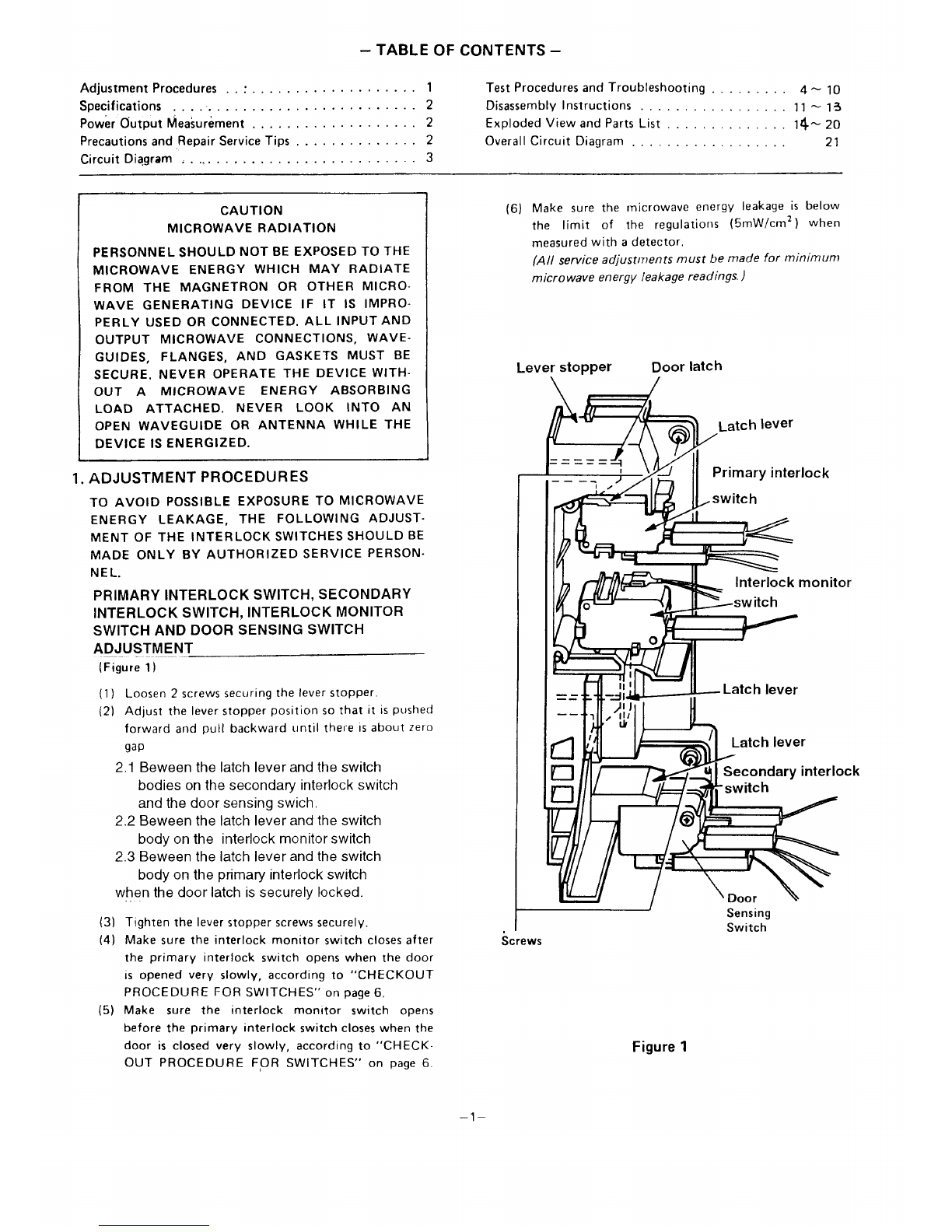
(1) Before the power is applied:
(a) Open and close the door several times to make
sure the primary interlock switch, the secondary
interlock switch, the interlock monitor switch
and the door sensing switch operate properly.
listen for the cliking sound from the switches.
Make sure the interlock monitor switch is
closed after the primary interlock switch is
opened when the door is opened.
(See pages 1 and 6)
(b) Make sure the perforated screen and the choke di-
electric of the door are correctly mounted.
(2) After the power is applied:
(a) Open and close the door to see If the interlock
mechanism operates properly.
(b) Check microwave energy leakage with aleakage
detector and confirm the energy leakage is below 5
mW/cm2 ).
(3) Do not operate the unit until it is completely repair-
ed, if any of the following conditions exists.
(a) Door does not close firmly against the cavity front.
(b) The hinge is broken.
(c) The choke dielectric or the door seal is damaged.
(d) The door is bent or warped, or there is any other
visible damage to the oven that may cause micro-
wave energy leakage.
(e) Make sure that there are no defective parts in the
interlock mechanism.
(f) Make sure there are no defective parts in the micro-
wave generating and transmission assembly. (espe-
cially waveguide).
(4) Following items should be checked after the unit is
repaired.
(a) The interlock monitor switch is connected correctly
and firmly.
(b) The magnetron gasket on the magnetron IS properly
positioned.
(c) Waveguide and oven cavity are intact (no leakage of
microwave energy).
(d) The door can be Properly closed and the safety
switches work Properly.
(e) The oven must be stopped when the door is opened
or the time is up
The oven must not be operated with any of the above
components removed or bypassed.
HINT FOR LAMP CHANGE
Before removing the cabinet, pull out the main plug.
If you want to check the new lamp with the oen
cabinet, take care of the following safety cautions.:
Do not touch live parts, The lamp holder is not connected
to the earth wotecton lead bv ametric screw.
–2–
5. CIRCUIT DIAGRAM
t
LN
P’ 1’
L
r——.
650JJH
8A(T~ 1
~650p HM“ /
2200 PF(Y)
1
X2
o. 06 EI)JF J
——
m
0
-Jt-
<0
Xu
al-
Wo
SW
l-nm
0
‘<z>
J-m
x
CJ
0
-II
Xucl
uul-
t-+-
az~
A- U-I
-11-
av
Xw CAVITY
ml- LIGHT
Wo
sSW
+b-- /0
HIGH VOLTAGE
TRANSFORMER
i\l
L_
‘] MDIODE
—
Mq
.— 1
MAGNETRON
+11 1
c
u-l
ml
Xm
.- V-1
L
/1:; Iw<
1-.-1
.- ZUJ
-m
~Parts rnarkedwiththis.signaresupplidwdh
uhighvottage exceeding 250V.
o
~Parts rnarlad with this sign have special
characteristics imptant for microwave leakage
When replacing any of these parts use only
manufacturers specified parts.
–3–
CONTROL
PRINTEO
CIRCUIT
BOARD
SI02
la
11 RL1
B
r—l
—
STEP 00WN
TRAN5FDRMER
Sloi
DOOR
SENSING
SWITCH
a
TIMER
!
TOUCH KEY
BOARO
6. TEST PROCEDURES AND TROUBLESHOOTING
CAUTION
—DISCONNECT THE POWER SUPPLY CORD
FROM THE WALL OUTLET WHENEVER RE-
MOVING THE CABINET FROM THE UNIT, PRO-
CEED WITH THE TESTS ONLY AFTER DIS-
CHARGING THE HIGH VOLTAGE CAPACITOR
AND REMOVING THE LEAD WIRES FROM THE
PRIMARY WINDING OF THE HIGH VOLTAGE
TRANSFORMER. (SEE FIGURE 3)
A. TEST PROCEDURES
COMPONENT
.— .-
MAGNETRON
HIGH-VOLTAGE
TRANSFORMER
—
CHECKOUT PROCEDURE
1)Check for resistance: Across the filament
terminals of the magnetron with an ohm-
meter on Rx 1 scale.
ohm-meter
2) Check for
Filament Windings
/
@
Q—
Figure 4
resistance: Between each flla.
ment terminal of the magnetron and the
chassis ground with an ohmmeter on
highest scale.
1
ohm-meter
1)Measure the resistance:
With an ohm-meter on Rx 1 scale.
a. Primary winding;
b, Filament winding;
c. Secondary winding;
2) Measure the resistance:
With an ohm-meter on highest scale.
a. Primary winding to ground;
b. Filament winding to ground;
,--- --*J j,
ohm-meter
Note: Remove varnish ot Figure
measured point.
6
Figure 3
RESULT
Normal reading.
Less than 1ohm
Normal reading:
Infinite ohms.
Normal readings:
Approximately 1.2 ohms.
Less than 1ohm
Approximately 72 ohms.
Normal readings:
Infinite ohms.
Infinite ohms.
–4-
COMPONENT CHECKOUT PROCEDURE RESULT
Measure the resitance:Across two terminals Normal reading:
with an ohm-meter on high est scale. Momentarily indicates several ohms, am
gradually returns to 10 meg-ohms,
Abnormal reading:
HIGH-VOLTAGE Indicates continuty or 10 meg-ohms frorr
CAPACITOR
um
the beginning.
including
BLEEDER’ Ohm-meter a
RESISTOR m
Figure 7
,—
Measure the resistance: Across two terminals Normal reading:
with an ohm-meter on Rx10,000 scale. Indicate about the middle position in one
direct (forward direction )and infinite
ohms in the reverse direction, using met[
((which is provided with a9-volt battery
Ohm-meter QNOTE
HIGH-VOLTAGE
“L
-Some digital meter may show over even
DIODE in aforward direction because low measur-
ing voltage of meter does not allow the
F&” 0 age diode,
meter current to pass through the high volt-
Abnormal reading:
Figure 8Indicates continuty or infinite ohms in boi
directions.
—
Measure the resistance: Across two terminals Normal reading:
with an ohmmeter on highest scale Indicates Infinite ohms In both directions
—
m
Abnormal reading.
Ohm-meter Indicates continuity In both dlrectlohs c
FUSE DIODE continuity In one dlrectlon and tnflnlt
ohms In reversed dlrectlon,
Figure 9
Measure the voltage: Between test points TP-41
TP.1, TP.2 or TP.3 and ground or between Test Point TP-1 TP2 TP.3 TP-5
TP.4 and TP.5. (See control clrcult board on
page 20) -5V -12V -30V 2.5V
Voltage DC Dc Dc Ac
CONTROL
CIRCUIT BOARD NOTE
-Proceed with the check of the step-
down transformer, to see if any one of
the mesuared values is different from
the specified values.
–5–
COMPONENT
TOUCH KEY
BOARD
CHECKOUT PROCEDURE
Measure the resistance between terminals of
FPC connector after removing it from SIOl.
(Figure 10) NOTE
–, When reconnecting the FPC connector,
make sure the holes on the connector are
properly inserted in hooks of the plastic
fastener in S101.
MATRIX CIRCUIT FOR
TOUCH KEYBOARD
FPC CONNECTOR
r———.—.—.—————————
c%=%=?-=?-:
Ir——
L-J
RESULT
Resistance
value
When checking “START” key, connect ohm
meter as iilust’ration below.
Oflm-meter
ToP
t/’
~)co
ocl
C2
C3
‘0
C3 f31
B2
Open
TERMINAL OF FPC CONNECTOR
Figure 10
CHECKOUT PROCEDURE FOR SWITCHES
Disconnect the lead wires from the switches and check for the continuity of the switches, connecting an ohm-meter to its ter-
minals.
—SWITCHES
(See Figure 1on page 1) CHECKOUT PROCEDURES DOOR OPEN
primary interlock,
o
0
Secondary interlock Terminals “COM” and “NO” +
Door Sensing
Interlock Monitor Terminals “COM” and “NC” m4°
DOOR CLOSED I
Wlw
CAUTION: After checking the switches, make sure that the interlock monitor switch is properly connected according to the
CIRCUIT DIAGRAM on page 3.
–6–
---- I-
..-— ---—
c
.-
d-.-.—- ---- —-— -. —. I---—- -
-—---.—— --—- -- -- —--- .
–7–
—
11
—— -- —-
Y
~J w~;
.—-——-———--?
-—-.---—
h’
.-
1
1
1-
-c I
_- __ —--
I
?
STEP SEQUEFJCE RESULT
—__._-—
1I
J
b
H.V
@@-@
.;,,—--—-J35\a&-\ Normal H.V
capacitor or
H,V. d!ode
mReplace Normal 1
IRuns
magnetron. magnetron. ,
w
transformer Resistance Check H.V. capacitor or HV. diode
e-l
OK with an ohm-meter after removing
lead wires. (See page 5) ~~kh Defective Replace H.V. Normal H.V. ~Runs
H.V. capacitor or capacitor or capacitor or I
Check resistance of H.V. diode H.V. d!ode, H.V. diode I
each wlndlng after
@e
,. ./-
removlng lead wires, ‘@
(See page 4). I
I
Resistance Replace H.V. Normal H.V. IRuns
Incorrect. transformer. transformer I
I
1
4) PROBLEM I
.OW microwave power
i( 3b
1
I
+
Normal
operation ‘
Check operallon of
blower motor when
START key IS
touched @-H-
NrI Temporarily short
operation across terminals
of thermal protectf
for magnetron and
thermal protector
for cavity by using
jumper lead.
@–-—---------& ;:.
I
I
@
Normal thermal ;_
Normal Replace thermal IRuns
protector for
operation protector for I
maanetron and thermal ~rotector for cavity. I
magnetron and
thermal protector
@*
I.’”
for cavity, I
GB
Reisstance :
Replace blower Normal blower ,Runs
/—\ .
/\— Incorrect. motor. molor,
\I
kk I
I
No Measure resistance lo
I
operation _24D
@1’
1.”/
of blower motor
Approx. 240 ohms. fI@
I
Normal Replace control Normal contrcl ~Runs
resistance circuit board. circuit board. I
I
I
u
c
z
u. w
u
—
>“
1“
I
(J
z
>
mI
.— -- ---- ___
1
m
---- ---- ---- .
r
L
4
–lo–
7. DISASSEMBLY INSTRUCTIONS
●
●
OVEN MUST BE DISCONNECTED FROM ELECT-
RICAL OUTLET WHEN MAKING REPLACEMENTS,
REPAIRS, ADJUSTMENTS AND CONTINUITY
CHECKS BEFORE PROCEEDING WITH ANY RE-
REPAIR WORK AFTER DISCONNECTING. WAIT AT
LEAST 1MINUTE, UNTIL THE CAPACITOR IN THE
HIGH-VOLTAGE AREA HAS FULLY DISCHARGED.
WHEN REPLACING ANY DOOR MICROSWITCH,
REPLACE WITH THE SAME TYPE SWITCH SPECIFI-
ED ON THE PARTS LIST.
A.REMOVING CONTROL CIRCUIT BOARD
-— -.
(1)
(2)
(3)
(4)
(5)
(6)
Remove 2upper screws and 3 bottom scrrew
securing the plastic frame. Release hook on the
left hand right sides of it from cavity front plate.
Remove all connectors from the control circuit
board.
Remove 3screws to detach the control panel
complete from the oven cavty.
Remove the FPC connector from the connector
S1OI while pushing up the end of the plastic
fastener.
Remove 2screws securing the step down
transformer on the control circuit board.
Lift up the control circuit board from its left
side and take it out from the control base
B.REMOVING TOUCH KEY BOARD
(1) Remove the FPC connector from the connector
S101 while pushing up the end of the plastic
fastener.
(2) Remove the control plate which is held on the
control base with the adhesive tape from the
control base.
(3) Remove the touch key board which is held on the
control base with the adhesive tape from the
control base.
C.REMOVING PRIMARY INTERLOCK SWITCH
AND/OR INTERLOCK MONITOR SWITCH
(See Figure 1 on page 1)
(1) Disconnect all lead wires from the primary
and/or monitor switches.
(2) Push rightward the switch while pressing the
switch stopper of the lever stopper(Figure 11-a)
until the switch plunger reaches the lever
stopper. Then remove it by lightly pressing the
switch plunger. (Figure 11-b)
(3) Make necessary adjustments or replacements
of the switch and check microwave energy
leakage according to “1. ADJUSTMENT PRO-
CEDURES” on page 1, after it is replaced with new
one, and check proper operation of it according to
“CHECKOUT PROCEDURE FOR SWITCHES”
on page 6.
D.REMOVING SECONDARY INTERLOCK SWITCH
AND DOOR SENSING SWiTCH
(1) Disconnect all lead wires from the secondary
interlock switch and the door sensing switch.
(2) Remove 1screw securing the switch,
(3) Make necessary adjustments replacements
of the switch and check microwave energy
leakage according to “1. ADJUSTMENT PRO-
CEDURES” on page 1, after it is replaced with new
one, and check proper operation of it according to
“CHECKOUT PROCEDURE FOR SWITCHES”
on page 6.
tch
pper
Push
rightward ress.
Figure Ii-a
Press.
Switch
Plunger h
Figure 11 -b
r--l
Interlock Switch Replacement –when replaclng
faulty switches be sure switch mounting tabs are not
bent, broken or otherwise deflclent In their ability
to secure the swttches in place.
–11–
E. REMOVING MAGNETRON
(1) Remove 2screws securing the thermal protector.
(2) Remove 4screws securing the stay.
(3) Remove each Iscrew to detach the duct of inlet
and outlet from the magnetron
t-l) Remove 4hex nuts securing the magnetron to
the wave guide. Take out the magnetron VERY
CAREFULLY.
NOTES
—When removing the magnetron, make sure that
its dome does not htt any adjacent parts, or it may
be damaged.
When replacing the magnetron, be sure to install
the magnetron gasket in the correct positio(l and be
sure that the gasket is in good condition.
—After replacrng the magnetron, check for micro
wave energy leakage with aleakage detector.
Microwave energy leakage must be below the limit
of 5mW/cm2.
G. REMOVING STIRRER FAN
(Figure 12)
(1) Pull out the stirrer cover toward you.
(2) Pinch the sirrer shaft by using long nose pliers
to remove the stopper from the stirrer shaft.
Remove the stirrer fan.
7/‘tirrer
se440fr
ew”
b’ Stopper Long nose pliers
Figure 12
~. REMOVING FUSE
Remove the 8A fuse with ascrewdriver.
NOTES
–When replacing the 8A fuse, be sure to use an
exact repair part.
-- If the 8A fuse blows immediately, check the
primary interlock switch, the relay 2(on the control
circuit board) and the interlock monitor switch
according to “CHECKOUT PROCEDURE FOR
SWITCHES” on page 6. And make sure to check the
microwave energy leakage according to “1, AD-
JUSTMENT PROCEDURES” on page 1, when the
primary interlock switch, the relay 2or the inter-
lock monitor switch is adjusted or replaced.
—If the primary interlock switch, the relay 2and
the interlock monitor switch operate properly,
determine which of the followings is defective:
control circuit board, blower motor, gear motor,
high voltage transformer, high voltage capacitor,
high voltage diode or magnetron.
—If the high voltage diode is defective, replace not
only the high voltage diode but also the fuse diode.
H. REMOVING DOOR
(1) Remove 2upper screws and 3 bottom screws
securing the plastic frame.
(2) Remove 2bolts securing the upper hinge.
(3) Tilt the top of the door toward you,
(4) Lift up the door to remove it.
NOTES
–After replacing the door, be sure to check that
the primary interlock switch, the door sensing
switch and, the interlock monitor switcl~ operate
normally. (See page 1)
–After replacing the door, check for microwave
energy leakage with aleakage detector, Microwave
energy leakage must be below the limit of 5mW/
cm2.
–12–
1.DISASSEMBLING DOOR
(1) Insert athi;flat blade screwdriver between
the choke dielectric and the door main frame
and lift up the choke dielectric to Irelease hooks
one by one.
(2) Remove the choke dielectric .
(3) Remove the plastic barrier which is held on the
door cover with the adhesive tape from the door
(4) Remove7 screws securing the door cover,
Hooks
Hooks
Door
Main I
Choke
Dlelectrlc
Figure 16
NOTES
–The choke dielectric may be damaged when it IS
removed. When reinstalling it replace it with new
ones if they are damaged.
–After installing the door in place, check for micro-
wave energy leakage with aleakage detector.
Microwave energy leakage must be below the limit
of 5mW/cm2.
–13–
0. EXPLODED VIEW AND PARTS LIST
CAVITY PARTS
/
Ilo” I\>
‘\A\ ‘“‘-
5\\\
–14–
CAVITY PARTS
!!Ill \---%+7/
t3
26
El Parts marked wih ths sign are supplkd with
high voltage exceeding 250v.
@, Parts ma~~ with th~ sign have special
charactetitb imprtant for microwave leakage.
When replacing any of these parts use only
manufactures specified parts.
–15–
(00) EM-C950UK
.
KEY NO. SERVICE PART NO. DESCRIPTION QTY.
1
2
3
4
5
6
7
8
9
10
11
12
13
14
15
16
17
18
19
20
21
22
23
24
25
26
27
28
29
30
31
32
33
34
35
36
37
38
39
40
41
42
43
44
45
46
47
617-055-9584
617-143-8321
617-002-1371
617-075-3906
617-143-8482
617-145-2754
617-076-3189
617-134-8088
617-077-6356
617-074-1729
617-080-6336
617-144-7613
617-144-1468
617-074-4249
617-080-4844
617-074-4140
617-058-6764
617-074-4454
402-061-1505
617-149-0824
617-125-3832
412-024-9400
617-120-8511
617-080-4776
617-080-6336
617-080-5483
617-080-4219
423-018-3809
617-124-0641
617-176-1627
617-075-1179
617-144-1475
617-188-6689
415-002-6507
617-075-3890
411-036-6803
617-004-5773
617-078-1275
617-004-5827
617-004-5780
617-068-3418
617-077-3386
411-073-0604
617-102-1240
617-068-3401
617-068-3449
411-004-3506
CABINET COVER ASS’Y
CABINET
THERMOSTAT 135C DIN HORTZ
DUCT/STIRRER FAN
FRAME, CONTROL
TRAY
LIGT OPENING COVER
LAMP 240V 25W E14 OKUNO
LAMP SOCKET OKUNO PAO 2A250VT150
GUIDE, STIRRER COVER
CANOE CLIP
STIRRER COVER
AIR GUIDE,STIRRER
STOPPER P.P
SPECIAL WASHER,8.5X16X0.5 T0.5XD16.5XD8.5
COLLAR,STIRRER SHAFT TEFLON
STIRRER FAN
STIRRER SHAFT
CERAMIC RES 25 J20W MTST ERF-20HMJ250
POWER CORD
BOTTOM BRACKET LGD T1.2 60160
SCR EVR PAN 4X12
CORD BUSHING HEIKO SR-6N-4STRAIGH
SPECIAL WASHER D9XD4.5XT1.5 P.E
CANOE CLIP
SPECIAL WASHER
SPECIAL SCREW
FUSE 250V 8A-M ELU DIN41571-T2
P.C.B COMP. NOISE FILTER TOKIN ME-2088D
BLOWER MOTOR BM-2628K(D) 220/240V
FAN P.P+GF20%
DUCT,MAGNETRON INLET P.P GF20%
WIRING LABEL PAPER 52.3G/M2
MAGNETRON 2M233H(M5)
DUCT, BLOWER
SCR PAN+SW+W 4X12
MICRO SWICH PRI, SEC YAMATAKE V-5230D-082
SWITCH SHEET POLYCARBONATE
MICRO SWITCH DOOR SENSIN V-5230DK-084YAMATAKE
MICRO SWITCH MONITOR V-5220D-081 YAMATAKE
LATCH LEVER
LATCH LEVER SHAFT 6NYLON GF30%
SCR TPG PAN 3X30
LEVER STOPPER P.P+GF20% V-71OO
LATCH LEVER DURACON GC-25 BK
LATCH LEVER DURACON GC-25
NUT HEX+FLG W/SRT 5
1
1
2
1
1
1
1
1
1
1
1
1
1
1
1
1
1
1
1
1
1
1
1
1
1
1
1
1
1
1
1
1
1
1
1
2
2
1
1
1
1
1
1
1
1
1
4
–16-
MICROWAVE PARTS
1
/
Q
\
P
a“’
./4
*,
47
/
13
10
6
@-
4X12 i\*
rPartsmarkedw!hthssignaresw@d vdh
9❑~ghVOtfageexceadng250v.
@pws~~+~hth~signkve~h’
chara erslcsImportantformkrowaveleakage.
Whenreplacinganyofthesepartsuseonly
manufacturersspecifiedpark
KEY NO. SERVICE PART NO. DESCRIPTION QTY.
1
2
3
4
5
6
7
8
9
10
11
12
13
617-188-3879
617-065-1066
617-141-6886
411-004-4503
411-008-1508
411-004-3506
617-143-8642
617-102-7495
411-010-5907
617-056-1617
411-089-2500
617-068-6006
412-018-2103
H.V CAPACITOR
LEAD WIRE ASS’Y
LEAD WIRE ASS’Y WITH
NUT HEX 4
WASHER SPR 4
NUT HEX+FLG W/SRT 5
H.V TRANSFORMER
SPECIAL SCREW
SCR EVR PAN 4X12
FOOT CUSHION ASS,Y
WASHER F5X1OXO.8
HINGE
BOLT HEX C-SCT 5X16
MTST 1.15 2.lKV 1
1
DIO 1
2
PBAWA M4 N1 1
2
H5T-C800UK 1
CAP TIGHT SELLATIONS 2
1
4
2
1
4
–17–
DOOR PARTS
/5
)&’-”
7
KEY NO.
1
2
3
4
5
6
7
8
9
10
11
12
13
SERVICE PART NO.
617-143-8369
617-143-8352
617-141-6947
617-056-6490
412-018-2103
617-068-5313
617-067-5079
617-067-4089
617-068-3289
617-068-1063
617-080-6732
617-081-0005
617-079-2929
DESCRIPTION QTY.
PLASTIC BARRIER, PANEL 1
DOOR COVER 1
FERRITE RUBBER 2
DOOR MAIN FRAME 1
BOLT HEX C-SCT 5X16 2
HINGE 1
CHOKE DIELECTRIC 1
DOOR SHEET 1
LATCH LEVER PAINTITE T1.O 1
DOOR LATCH POLYACETAL GF 25% 2
SPEED NUT SPN-2ACP 2
SPRING SUS304 WPA D1.2 1
VINYL TUBE 1
–18–
CONTROL PANEL PARTS 6
/
2
I
Items 15 and 16 is not illustrated l--’K#‘“’ \
f[2 11
/’
3
,“
3X14
,&f@
9
/’-’ 310
-ffs!! “,
.—
.——.-
KEY NO. SERVICE PART NO. DESCRIPTION QTY.
1617-143-8475
2617-143-8468
3617-076-2250
4617-141-6992
6617-143-9823
8617-077-3263
9617-068-3388
10 617-144-1482
11 617-124-8104
12 617-124-8142
13 617-068-0615
14 617-080-9559
15 617-131-2775
16 617-188-6672
TOUCH KEY BOARD
CONTROL PLATE
CONTROL BASE ASS T2
FERRITE RUBBER
P.C.B COMP.
LATCH LEVER SHAFT
DOOR RELEASE LEVER
VAR. RESISTOR ASS’Y
KNOB BASE
KNOB ABS NN-B
1
1
1
1
1
1
0
0
“
:
1
DOOR LEREASE BUTTON 1
SUS304-WPA DO.8 1
SPRING 1
MENU LABEL 1
OPERATING INSTRUCTIONS A
–19–

Other manuals for EM-C950

1

Other Sanyo Microwave Oven manuals

Sanyo EM-S7720V User manual

Sanyo

Sanyo EM-S7720V User manual

Sanyo EM-C5779V User manual

Sanyo

Sanyo EM-C5779V User manual

Sanyo EM590 User manual

Sanyo

Sanyo EM590 User manual

Sanyo EM-S1553 User manual

Sanyo

Sanyo EM-S1553 User manual

Sanyo EM-N102 User manual

Sanyo

Sanyo EM-N102 User manual

Sanyo EMN-109 User manual

Sanyo

Sanyo EMN-109 User manual

Sanyo EM5602B User manual

Sanyo

Sanyo EM5602B User manual

Sanyo EM-5646 User manual

Sanyo

Sanyo EM-5646 User manual

Sanyo EM-C2000 User manual

Sanyo

Sanyo EM-C2000 User manual

Sanyo EM-V890 Operating manual

Sanyo

Sanyo EM-V890 Operating manual

Sanyo EM-S154 User manual

Sanyo

Sanyo EM-S154 User manual

Sanyo EM-S8597V User manual

Sanyo

Sanyo EM-S8597V User manual

Sanyo EM-X491S User manual

Sanyo

Sanyo EM-X491S User manual

Sanyo EM-D9950ECO User manual

Sanyo

Sanyo EM-D9950ECO User manual

Sanyo EM-C950 User manual

Sanyo

Sanyo EM-C950 User manual

Sanyo EM-U1000W User manual

Sanyo

Sanyo EM-U1000W User manual

Sanyo EM-G5596V UK2 User manual

Sanyo

Sanyo EM-G5596V UK2 User manual

Sanyo EM-C1850 User manual

Sanyo

Sanyo EM-C1850 User manual

Sanyo EM-U1000W Use and care manual

Sanyo

Sanyo EM-U1000W Use and care manual

Sanyo EM-X600S User manual

Sanyo

Sanyo EM-X600S User manual

Sanyo EM-G5595S User manual

Sanyo

Sanyo EM-G5595S User manual

Sanyo EM-A5410 Use and care manual

Sanyo

Sanyo EM-A5410 Use and care manual

Sanyo EM-S7595S User manual

Sanyo

Sanyo EM-S7595S User manual

Sanyo EM-G450 User manual

Sanyo

Sanyo EM-G450 User manual

Popular Microwave Oven manuals by other brands

Frigidaire FFCM0934L Specifications

Frigidaire

Frigidaire FFCM0934L Specifications

Bosch CFA634GS1B instruction manual

Bosch

Bosch CFA634GS1B instruction manual

LG LRM1230W Service manual

LG

LG LRM1230W Service manual

Inglis IRH320 Use & care guide

Inglis

Inglis IRH320 Use & care guide

Insignia NS-MW09SS8 user guide

Insignia

Insignia NS-MW09SS8 user guide

Panasonic NN-SD372S operating instructions

Panasonic

Panasonic NN-SD372S operating instructions

Electrolux COM700CX user manual

Electrolux

Electrolux COM700CX user manual

Maytag JMV8186AA Series Service manual

Maytag

Maytag JMV8186AA Series Service manual

Frigidaire 316495055 Use & care manual

Frigidaire

Frigidaire 316495055 Use & care manual

Kenmore 87000 user manual

Kenmore

Kenmore 87000 user manual

Panasonic NN-ST452W Service manual

Panasonic

Panasonic NN-ST452W Service manual

ETNA ECM274RVS Instructions for use

ETNA

ETNA ECM274RVS Instructions for use

HELLER HMW25B user manual

HELLER

HELLER HMW25B user manual

GE VM141J Use and care guide

GE

GE VM141J Use and care guide

GE JKP90SM datasheet

GE

GE JKP90SM datasheet

AEG KMK525000M user manual

AEG

AEG KMK525000M user manual

Hyundai H-MW1120 instruction manual

Hyundai

Hyundai H-MW1120 instruction manual

arcelik MD 2310 W manual

arcelik

arcelik MD 2310 W manual

manuals.online logo
manuals.online logoBrands
  • About & Mission
  • Contact us
  • Privacy Policy
  • Terms and Conditions

Copyright 2025 Manuals.Online. All Rights Reserved.