manuals.online logo
Brands
  1. Home
  2. •
  3. Brands
  4. •
  5. Sanyo
  6. •
  7. Projector
  8. •
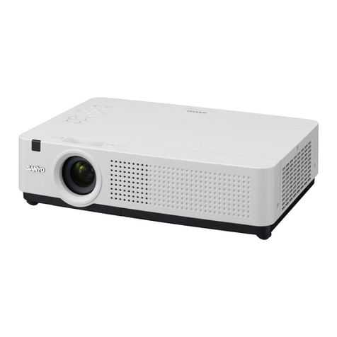
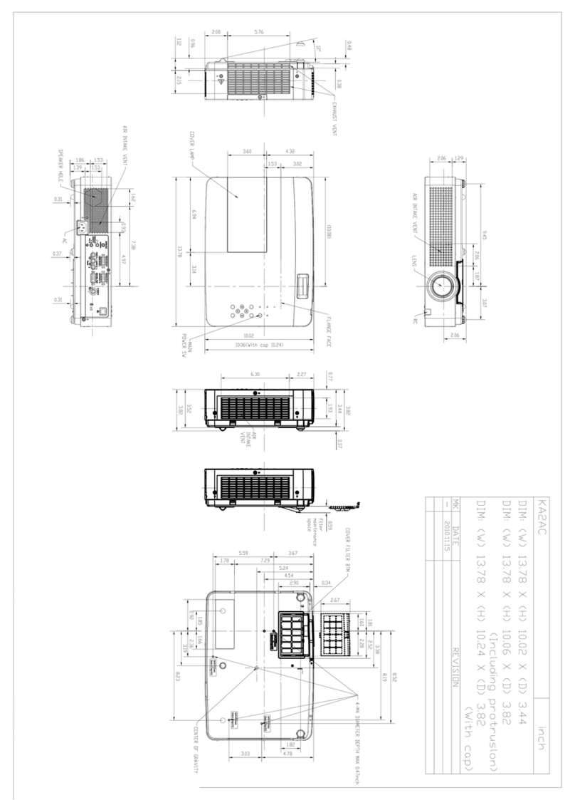
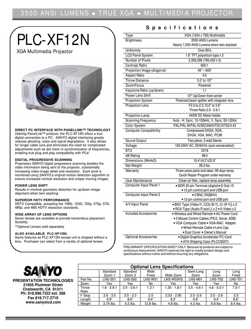
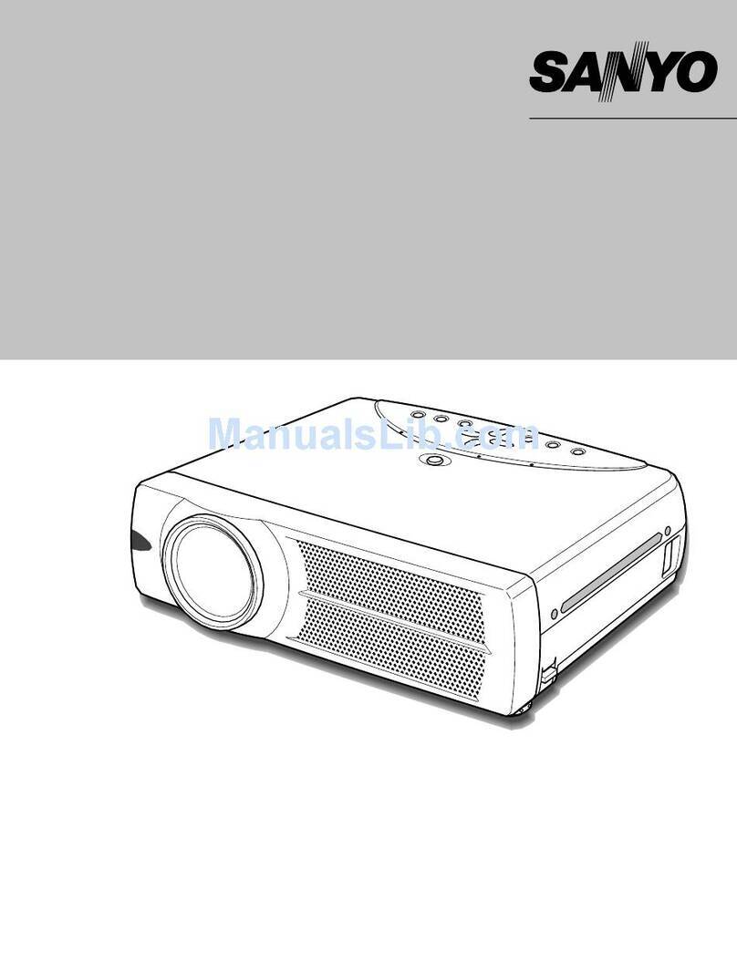
  9. Sanyo PLC-SU50 User manual

Sanyo PLC-SU50 User manual

Other manuals for PLC-SU50

1

Other Sanyo Projector manuals

Sanyo PLV-Z2 User manual

Sanyo

Sanyo PLV-Z2 User manual

Sanyo PLC-SP10N User manual

Sanyo

Sanyo PLC-SP10N User manual

Sanyo PLC-XU300A - 3000 Lumens User manual

Sanyo

Sanyo PLC-XU300A - 3000 Lumens User manual

Sanyo PJLINK PDG-DXL100 User manual

Sanyo

Sanyo PJLINK PDG-DXL100 User manual

Sanyo PLC-XU106 Guide

Sanyo

Sanyo PLC-XU106 Guide

Sanyo PLC-WXU3ST User manual

Sanyo

Sanyo PLC-WXU3ST User manual

Sanyo PLC-XW250 - 2600 Lumens User manual

Sanyo

Sanyo PLC-XW250 - 2600 Lumens User manual

Sanyo PLC-SU31 User manual

Sanyo

Sanyo PLC-SU31 User manual

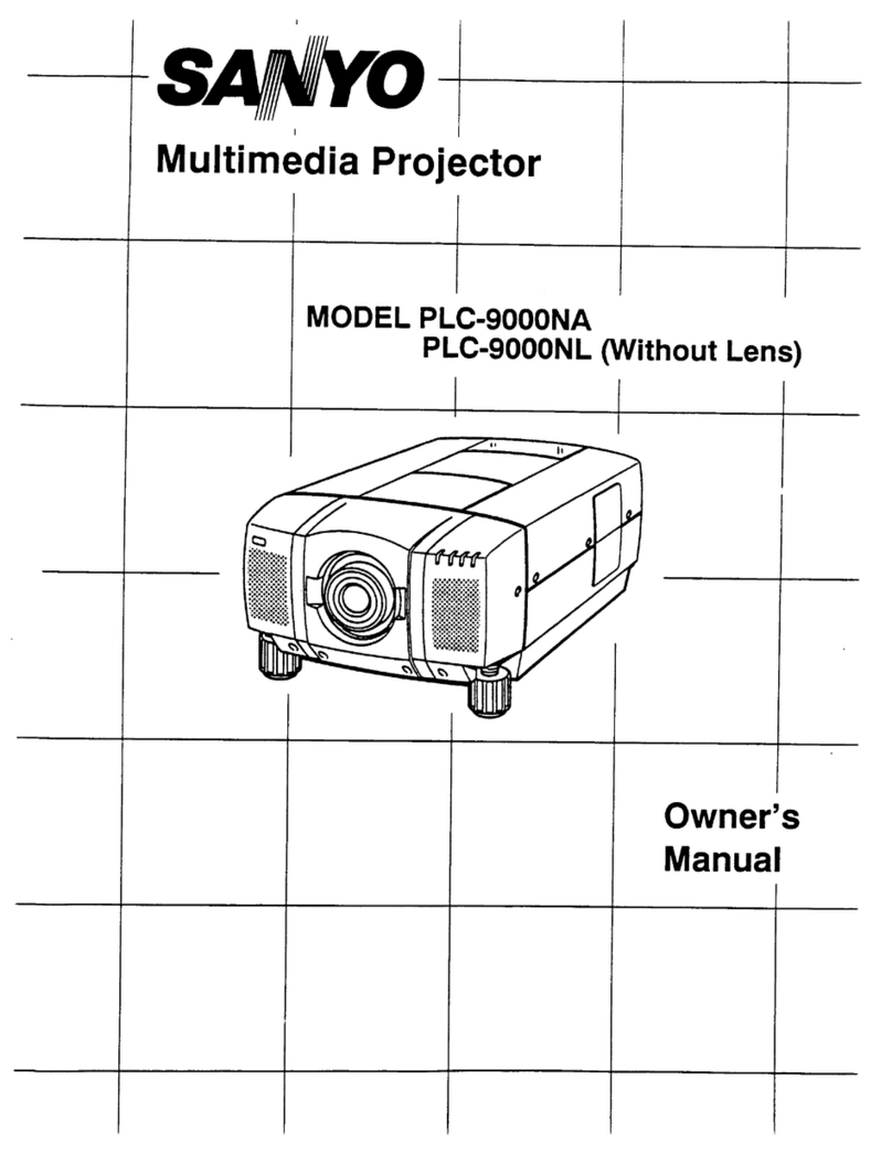
Sanyo PLC-9000NA User manual

Sanyo

Sanyo PLC-9000NA User manual

Sanyo PLC-EF10EA User manual

Sanyo

Sanyo PLC-EF10EA User manual

Sanyo WXU700A User manual

Sanyo

Sanyo WXU700A User manual

Sanyo PLC-WL2500 User manual

Sanyo

Sanyo PLC-WL2500 User manual

Sanyo PLC-XK2200 User manual

Sanyo

Sanyo PLC-XK2200 User manual

Sanyo PLC-XU47 User manual

Sanyo

Sanyo PLC-XU47 User manual

Sanyo PDG-DSU30 - 2500 User manual

Sanyo

Sanyo PDG-DSU30 - 2500 User manual

Sanyo PLC-XL45 User manual

Sanyo

Sanyo PLC-XL45 User manual

Sanyo PLC-XP10E Setup guide

Sanyo

Sanyo PLC-XP10E Setup guide

Sanyo PLC-WXU30A User manual

Sanyo

Sanyo PLC-WXU30A User manual

Sanyo PLV-HD10 User manual

Sanyo

Sanyo PLV-HD10 User manual

Sanyo PLC-XP45 User manual

Sanyo

Sanyo PLC-XP45 User manual

Sanyo PLC-XU116 User manual

Sanyo

Sanyo PLC-XU116 User manual

Sanyo SW15 - PLC SVGA LCD Projector User manual

Sanyo

Sanyo SW15 - PLC SVGA LCD Projector User manual

Sanyo PLC-WXU30 User manual

Sanyo

Sanyo PLC-WXU30 User manual

Sanyo PLV-HD2000E User manual

Sanyo

Sanyo PLV-HD2000E User manual

Popular Projector manuals by other brands

Eiki LC-X985 Specification sheet

Eiki

Eiki LC-X985 Specification sheet

InFocus LitePro 610 quick start

InFocus

InFocus LitePro 610 quick start

Epson EH-TW5900 datasheet

Epson

Epson EH-TW5900 datasheet

FOREVER MLP-100 manual

FOREVER

FOREVER MLP-100 manual

Toshiba TDP-MT8U Specifications

Toshiba

Toshiba TDP-MT8U Specifications

Mitsubishi XD500U specification

Mitsubishi

Mitsubishi XD500U specification

Kodak Ektapro 3020 Illustrated parts list

Kodak

Kodak Ektapro 3020 Illustrated parts list

Toshiba TDP-EW25U Specifications

Toshiba

Toshiba TDP-EW25U Specifications

Barco iQ PRO G500 supplementary guide

Barco

Barco iQ PRO G500 supplementary guide

NEC Showcase Series HT1100 user manual

NEC

NEC Showcase Series HT1100 user manual

Philips LC1341 user guide

Philips

Philips LC1341 user guide

Epson PowerLite 1266 user guide

Epson

Epson PowerLite 1266 user guide

MAGINON DLP 1400S user manual

MAGINON

MAGINON DLP 1400S user manual

Toshiba TLP-380 owner's manual

Toshiba

Toshiba TLP-380 owner's manual

Philips PicoPix PPX2480/EU user manual

Philips

Philips PicoPix PPX2480/EU user manual

Hitachi CP-X605 Series Specifications

Hitachi

Hitachi CP-X605 Series Specifications

Optoma TW1692 user manual

Optoma

Optoma TW1692 user manual

Kodak EKTAPRO instruction manual

Kodak

Kodak EKTAPRO instruction manual

manuals.online logo
manuals.online logoBrands
  • About & Mission
  • Contact us
  • Privacy Policy
  • Terms and Conditions

Copyright 2025 Manuals.Online. All Rights Reserved.

Multimedia Projector
SERVICE MANUAL
PRODUCT CODE
1 122 219 00 (MB7A)
1 122 220 00 (PB7A)
1 122 220 02 (PB7C)
Original Version
REFERENCE NO. SM5110518-00
FILE NO.
Model No. PLC-SU50
U.S.A., Canada,
Europe, Asia, Africa
U.K.
Chassis No. MB7-SU5000
NOTE: Match the Chassis No. on the unit’s
back cover with the Chassis No. in the
Service Manual.
If the Original Version Service
Manual Chassis No. does not match
the unit’s, additional Service
Literature is required.You must refer to
“Notices” to the Original Service
Manual prior to servicing the unit.
-18-
■Optical Adjustments
[Before Adjustment]
- Input a 100% of black raster signal.
1Loosen a screw A(Fig.1-1/1-2) on the polarized glass mounting
base which you intend to adjust.
2Turn the polarized glass mounting base as shown in Fig.1-1 to
obtain the darkest brightness on the screen.
3Tighten the screw Ato fix the polarized glass mounting base.
Repeat steps 1 to 3 for remaining polarized glasses.
B-Polarized Glass
Mounting Base
R-Polarized Glass
Mounting Base
G-Polarized Glass
Mounting Base
A
A
A
Fig.1-2
Fig.1-1
Polarized glass
mounting base
Main Board
A
Contrast adjustment
Before taking optical adjustments below, remove the Cabinet Top following to the “Mechanical Disassemblies”.
Adjustments require a 2.0mm hex wrench and a slot screwdriver. When you adjust Integrator lens or Relay lens
adjustment, you need to disconnect FPC cables of LCD panels on the main board.
Optical adjustment requires a 2.0mm hex wrench and a slot screwdriver.
Note: Do not disconnect connectors on the main board, because the projector cannot turn on due to operate the
power failure protection.
-19-
1 Turn the projector on by a state of without FPC cables.
2 Project all of lights on the screen.
3 Adjust the adjustment base of integrator lens assy to make color
uniformity in white.
1) If the shading appears on the left or right of the screen as
shown in Fig.2-1, loosen 2 screws A, and adjust the slot Bto
make color uniformity in white by using a slot screwdriver.
2) If the shading appears on the top or bottom of the screen as
shown in Fig.2-2, loosen 2 screws C, and adjust the slot Dto
make color uniformity in white by using a slot screwdriver
4 Tighten screws Aand Cto fix the Integrator lens unit.
Note:
The relay lens adjustment must be carried out after completing this
adjustment.
Optical Adjustments
Integrator lens adjustment
Fig.2-2
y
x
Moving of Slot D
Slot D
ab
a
b
Moving of slot B
Fig.2-1
Slot B
A
C
y
x
White
White
A
-20-
1Turn the projector on by a state of without FPC cables.
2 Project all of lights on the screen.
3Adjust the adjustment base of relay lens assy to make color unifor-
mity in white.
If the shading appears on the left or right of the screen as shown in
Fig.3, loosen 1 screw A, and adjust the slot Bto make color unifor-
mity in white by using a slot screwdriver.
4Tighten the screws Ato fix the relay lens unit.
Fig.3
A
Slot B
a
b
b
Moving of slot B
a
White
Relay lens-Out adjustment
Optical Adjustments
-21-
To enter the service mode
To enter the “Service Mode”, press and hold the MENU and INPUT buttons on the projector at the same time for
more than 3 seconds. The service menu appears on the screen as follows.
To adjust service data
Select the adjustment group no. by pressing the MENU (+) or KEYSTONE (-) button, and select the adjustment
item no. by pressing the pointer UP or DOWN button, and change the data value by pressing the VOLUME – or
VOLUME + button.Refer to the “Service Adjustment Data Table” for further description of adjustment group no.,
item no. and data value.
To exit the service mode
To exit the service mode, press the POWER ON-OFF button on the projector or remote control unit.
●Service Adjustment Menu Operation
IC1801 on the main board stores the data for the serv-
ice adjustments, and should not be replaced except for
the case of defective device.
If replaced, the re-adjustments are required following to
the “Electrical Adjustments”.
The data of lamp replacement counter is stored in the
IC1801.
Please note that the lamp replace counter will be reset
when the memory IC (IC1801) is replaced.
(Lamp replace counter cannot be set to the previous
value.)
● Caution to memory IC replacement
When IC1801 is replaced with new one, the CPU
writes down the default data of the service adjustments
to the replaced IC as the mentioned on the service
adjustment table. As these data are not the same data
as factory shipped data, it should be required to per-
form the re-adjustments following to the “Electrical
Adjustments”.
Please note that in this case the lamp replace counter
will be reset.
● Caution of Main Board replacement (in the case
Ic1801 is not defective)
When the main board is replaced, IC1801 should be
replaced with the one on previous main board. After
replacement, it should be required to perform the re-
adjustments following to the “Electrical Adjustments”.
In this case, the lamp replace counter can be kept the
value as before.
● Memory IC Replacement
ON -OFF
POWER
KEYSTONE
INPUT
WARNING
LAMP
REPLACE
MENU
V
O
L
U
M
E
–
V
O
L
U
M
E
+
SELECT
Service Mode
Input Video
Group No. Data
0032
Ver. 1 .00
Data value
Item No.
■Electrical Adjustments
Group No.
-22-
[Adjustment Condition]
●Input signal
Video signal .......................... 1.0Vp-p/75Ωterminated, 16 steps gray
scale (Composite video signal)
Computer signal .................... 0.7Vp-p/75Ωterminated, 16 steps gray
scale pattern
Component Video signal ...... 0.7Vp-p/75Ωterminated, 16 steps gray
scale (Component video signal with
480p, 575p, 720p or 1080i format)
●Picture control mode .............. “STANDARD” mode unless otherwise
noted.
Note:
* Please refer to “Service Adjustment Menu Operation” for entering the service mode and adjusting the service
data.
White 100% Black 100%
●Circuit Adjustments
CAUTION: The each circuit has been made by the fine adjustment at factory. Do not attempt to adjust the follow-
ing adjustments except requiring the readjustments in servicing otherwise it may cause loss of per-
formance and product safety.
Electrical Adjustments
16 steps gray scale pattern
After replacing the Power Board readjust the Output
voltage adjustment as follows.
1. Connect a digital voltmeter to pins 1 (+) and 3 (-) of
K6D.
2. Adjust the voltage by using VR611 as following.
AC Input Reading
230V 380V ±2V
Caution:
Be sure to connect the lamp when taking this adjust-
ment.
Output Voltage adjustment
1. Set the lamp mode to "Normal" and then enter the
service mode.
2. Select group no. “111”, item no. “5”and set data value
to “1”.
3. Connect a digital voltmeter to test point “TP12V1”(+)
and chassis ground (-). Select item no. “89”and
change data value to adjust voltage to be 7.0 ±0.1V.
4. Connect a digital voltmeter to test point “TP12V2”
(+) and chassis ground (-). Select item no. “91”and
change data value to adjust voltage to be 7.0 ±0.1V.
5. Connect a digital voltmeter to test point “TP12V1”(+)
and chassis ground (-). Select item no. “90”and
change data value to adjust voltage to be 13.5 ±0.1V.
6. Connect a digital voltmeter to test point “TP12V2”(+)
and chassis ground (-). Select item no. “92”and
change data value to adjust voltage to be 13.5 ±0.1V.
7. Select item no. “5”and set data value to “0”.
zFan Control adjustment
* This adjustment is not required even if the power
board is replaced because this adjustment is carried
out before parts shipment.
-23-
Electrical Adjustments
1. Receive the 16-step grey scale computer signal with
Computer2 [RGB] mode.
2. Enter the service mode.
3. Connect an oscilloscope to test point “TPG1”(+) and
chassis ground (-).
4. Select group no. “0”, item no. “0”and change data
value to adjust the pedestal level and black level to be
the same level.
5. Connect an oscilloscope to test point “TPR1”(+) and
chassis ground (-).
6. Select item no. “1”and change data value to adjust the
pedestal level and black level to be the same level.
7. Connect an oscilloscope to test point “TPB1”(+) and
chassis ground (-).
8. Select item no. “2”and change data value to adjust the
pedestal level and black level to be the same level.
Pedestal Lebel
Black Lebel
xClamp adjustment [PC]
1. Receive the 16-step grey scale component signal
with Computer2 [Component] mode.
2. Enter the service mode.
3. Connect an oscilloscope to test point “TPG1”(+) and
chassis ground (-).
4. Select group no. “0”, item no. “0”and change data
value to adjust the pedestal level and black level to be
the same level.
5. Connect an oscilloscope to test point “TPR1”(+) and
chassis ground (-).
6. Select group no. “0”, item no. “1”and change data
value to adjust the pedestal level and black level to be
the same level.
7. Connect an oscilloscope to test point “TPB1”(+) and
chassis ground (-).
8. Select group no. “0”, item no. “2”and change data
value to adjust the pedestal level and black level to be
the same level.
Pedestal Lebel
Black Lebel
vClamp adjustment [COMPONENT]
1. Receive the 16-step gray scale composite video sig-
nal with Video [Video] mode.
2. Enter the service mode.
3. Connect an oscilloscope to test point “TPG1”(+) and
chassis ground (-).
4. Select group no. “0”, item no. “0”and change data
value to adjust the pedestal level and black level to be
the same level.
5. Connect an oscilloscope to test point “TPR1”(+) and
chassis ground (-).
6. Select item no. “1”and change data value to adjust the
pedestal level and black level to be the same level.
7. Connect an oscilloscope to test point “TPB1”(+) and
chassis ground (-).
8. Select item no. “2”and change data value to adjust the
pedestal level and black level to be the same level.
Pedestal Lebel
Black Lebel
cClamp adjustment [AV]
-24-
Electrical Adjustments
1. Receive the 16-step grey scale computer signal with
Computer2 [RGB] mode.
2. Enter the service mode
3. Connect a digital voltmeter to test point “TPG1”(+)
and chassis ground (-).
4. Select group no. “10”, item no. “0”and change data
value to adjust the voltage to be 7.50 ±0.05V.
5. Connect a digital voltmeter to test point “TPR1”(+)
and chassis ground (-).
6. Select item no. “1”and change data value to adjust
the voltage to be 7.50 ±0.05V.
7. Connect a digital voltmeter to test point “TPB1”(+)
and chassis ground (-).
8. Select item no. “2”and change data value to adjust
the voltage to be 7.50 ±0.05V.
mVideo Center adjustment
1. Receive the 16-step grey scale composite video sig-
nal with Video [Video] mode.
2. Enter the service mode.
3. Connect an oscilloscope to test point “TPG1”(+)
and chassis ground (-).
4. Select group no. “9”, item no. “1”and adjust the ampli-
tude “a” to be minimum by changing the Data value.
5. Connect an oscilloscope to test point “TPR1”(+) and
chassis ground (-).
6. Select item no. “2”and adjust the amplitude “a” to be
minimum by changing the Data value.
7. Connect an oscilloscope to test point “TPB1”(+) and
chassis ground (-).
8. Select item no. “3”and adjust the amplitude “a” to be
minimum by changing the Data value.
(a)
White Level
6n Sub Gain adjustment [Video]
1. Receive the 16-step grey scale computer signal with
Computer2 [RGB] mode.
2. Enter the service mode.
3. Connect an oscilloscope to test point “TPG1”(+)
and chassis ground (-).
4. Select group no. “9”, item no. “1”and adjust the ampli-
tude “a” to be minimum by changing the Data value.
5. Connect an oscilloscope to test point “TPR1”(+) and
chassis ground (-).
6. Select item no. “2”and adjust the amplitude “a” to be
minimum by changing the Data value.
7. Connect an oscilloscope to test point “TPB1”(+) and
chassis ground (-).
8. Select item no. “3”and adjust the amplitude “a” to be
minimum by changing the Data value.
(a)
White Level
bSub Gain adjustment [PC]
1. Receive the 16-step gray scale computer signal with
Computer2 [RGB] mode.
2. Enter the service mode.
3. Connect an oscilloscope to test point “TPPSIG”(+)
and chassis ground (-).
4. Select group no. “10”, item no. “14”and adjust the
amplitude “a” to be 10.0 ±0.1V by changing the Data
value.
5. Select item no. “17”and adjust the amplitude “b” to be
3.8 ±0.1V by changing the Data value.
3. Connect an oscilloscope to test point “TPZPSIG”(+)
and chassis ground (-).
4. Select group no. “10”, item no. “12”and adjust the
amplitude “a” to be 10.0 ±0.1V by changing the Data
value.
5. Select item no. “15”and adjust the amplitude “b” to be
3.8 ±0.1V by changing the Data value.
(a)
(b)
,PSIG adjustment
-25-
Electrical Adjustments
t1. Receive the 1 line black/white pattern computer sig-
nal with Computer2 [RGB] mode.
2. Enter the service mode.
3. Project only green light component to the screen.
4. Select group no. “10”, item no. “9”and change data
value to obtain the minimum flicker on the screen.
5. Project only red light component to the screen.
6. Select item no. “10”and change data value to obtain
the minimum flicker on the screen.
7. Project only blue light component to the screen.
8. Select item no. “11 and change data value to obtain
the minimum flicker on the screen.
⁄0 Common Center adjustment
[PC WHITE BALANCE ADJUSTMENT]
1. Receive the 16-step gray scale computer signal with
Computer2 [RGB] mode.
2. Enter the service mode, select group no. “9”item no.
“11”(Red) or “12”(Blue), and change Data values
respectively to make a proper white balance.
[AV WHITE BALANCE ADJUSTMENT]
1. Receive the 16-step gray scale composite video sig-
nal with Video [Video] mode.
2. Enter the service mode, select group no. “9”item no.
“11”(Red) or “12”(Blue), and change Data values
respectively to make a proper white balance.
Confirm that the same white balance is obtained in
video and computer input.
⁄2 White Balance adjustment
If you find the color shading on the screen, please
adjust the white uniformity by using the proper comput-
er and “Color Shading Correction” software supplied
separately.
The software can be ordered as follows;
COLOR SHADING CORRECTION ver. 3.0
Service Parts No.645 056 6288
NOTE ON WHITE UNIFORMITY
ADJUSTMENT
1. Receive the 16-step grey scale computer signal with
Computer2 [RGB] mode.
2. Enter the service mode.
3. Connect an oscilloscope to test point “TPG1”(+)
and chassis ground (-).
4. Select group no. “10”, item no. “3”and change data
value to adjust amplitude “a” to be 9.8 ±0.1V.
5. Connect an oscilloscope to test point “TPR1”(+) and
chassis ground (-).
6. Select item no. “4”and change data value to adjust
amplitude “a” to be 9.8 ±0.1V.
7. Connect an oscilloscope to test point “TPB1”(+) and
chassis ground (-).
8. Select item no. “5”and change data value to adjust
amplitude “a” to be 9.8 ±0.1V.
(a)
black level
black level
.Black Reference adjustment
[PC-GAMMA ADJUSTMENT]
1. Receive the 16-step grey scale computer signal with
Computer2 [RGB] mode.
2. Enter the service mode.
3. Connect an oscilloscope to test point “TPG1”(+)
and chassis ground (-).
4. Select group no. “9”, item no. “10”and change data
value to adjust amplitude “a” to be 2.0 ±0.1V.
[AV-GAMMA ADJUSTMENT]
1. Receive the 16-step grey scale video signal with
Video [Video] mode.
2. Enter the service mode.
3. Connect an oscilloscope to test point “TPG1”(+)
and chassis ground (-).
4. Select group no. “9”, item no. “10”and change data
value to adjust amplitude “a” to be 1.3 ±0.1V.
(a)
white level
white level
112⁄1 Gamma adjustment
-26-
K6K K6M
K8F
IC201
IC3101
TPVS
TP52G TP52B
K8N
IC2101
TPZPSIG
IC3801
TP52R
K5G IC3851
TPG1
IC5201
IC1201
TP12V1
IC1381
IC5341
K5R
IC5351
TPB1
K5B
K8X
TP12V2
K8P
IC801
IC6211
K8A
IC1851
IC1451
K8H
TPR1
K6L K8D
IC401
TPPSIG
TP21R
TP21G
TP21B
TPHS
Electrical Adjustments
MAIN BOARD
●Test Points and Locations