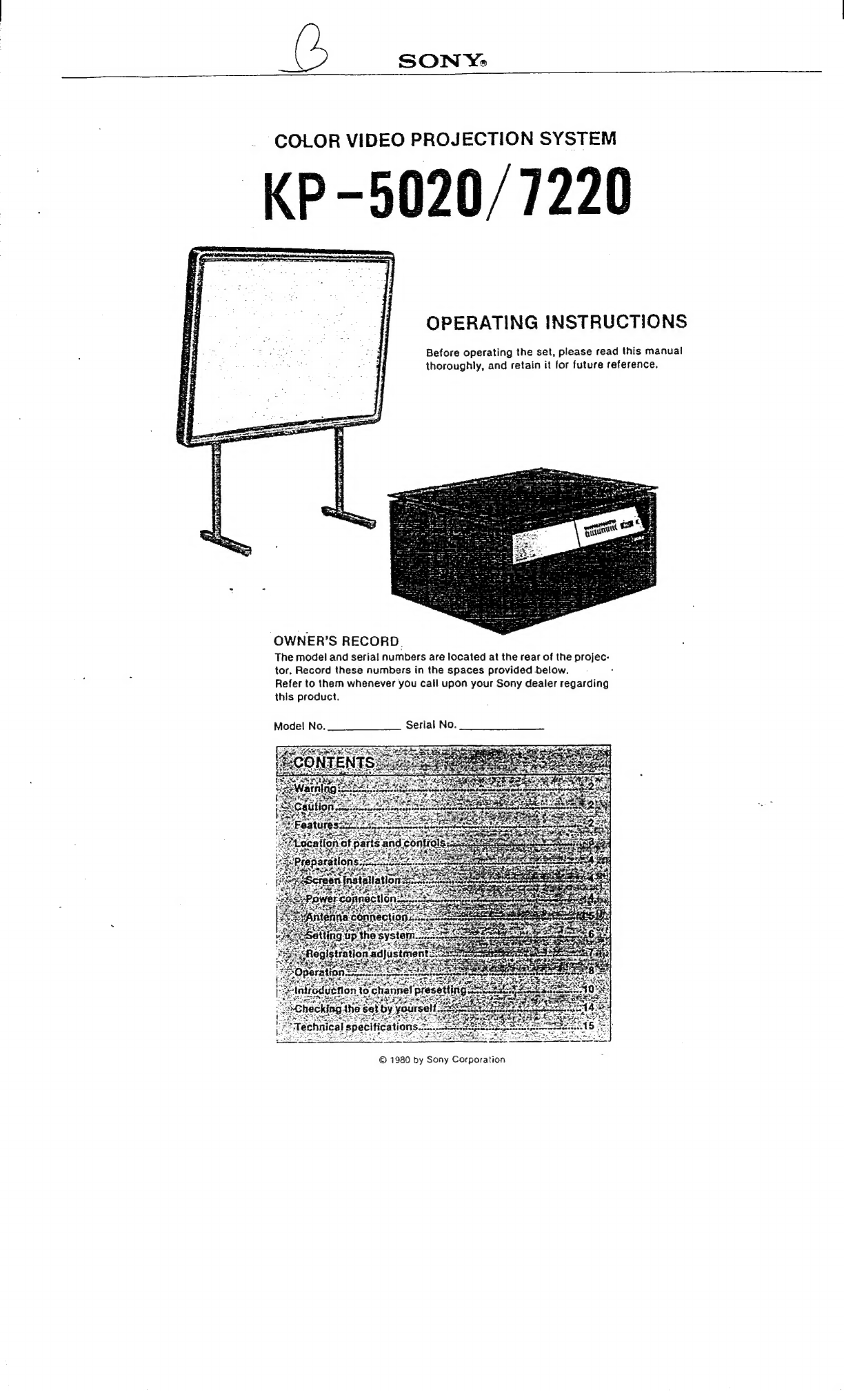
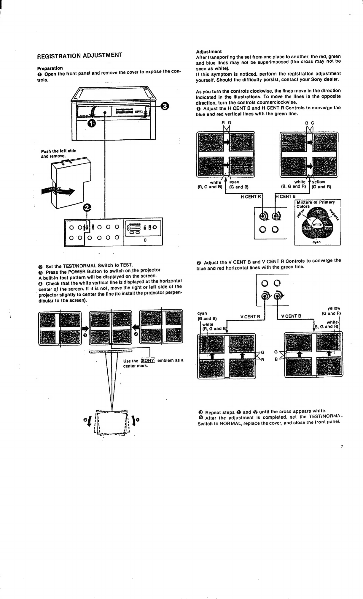
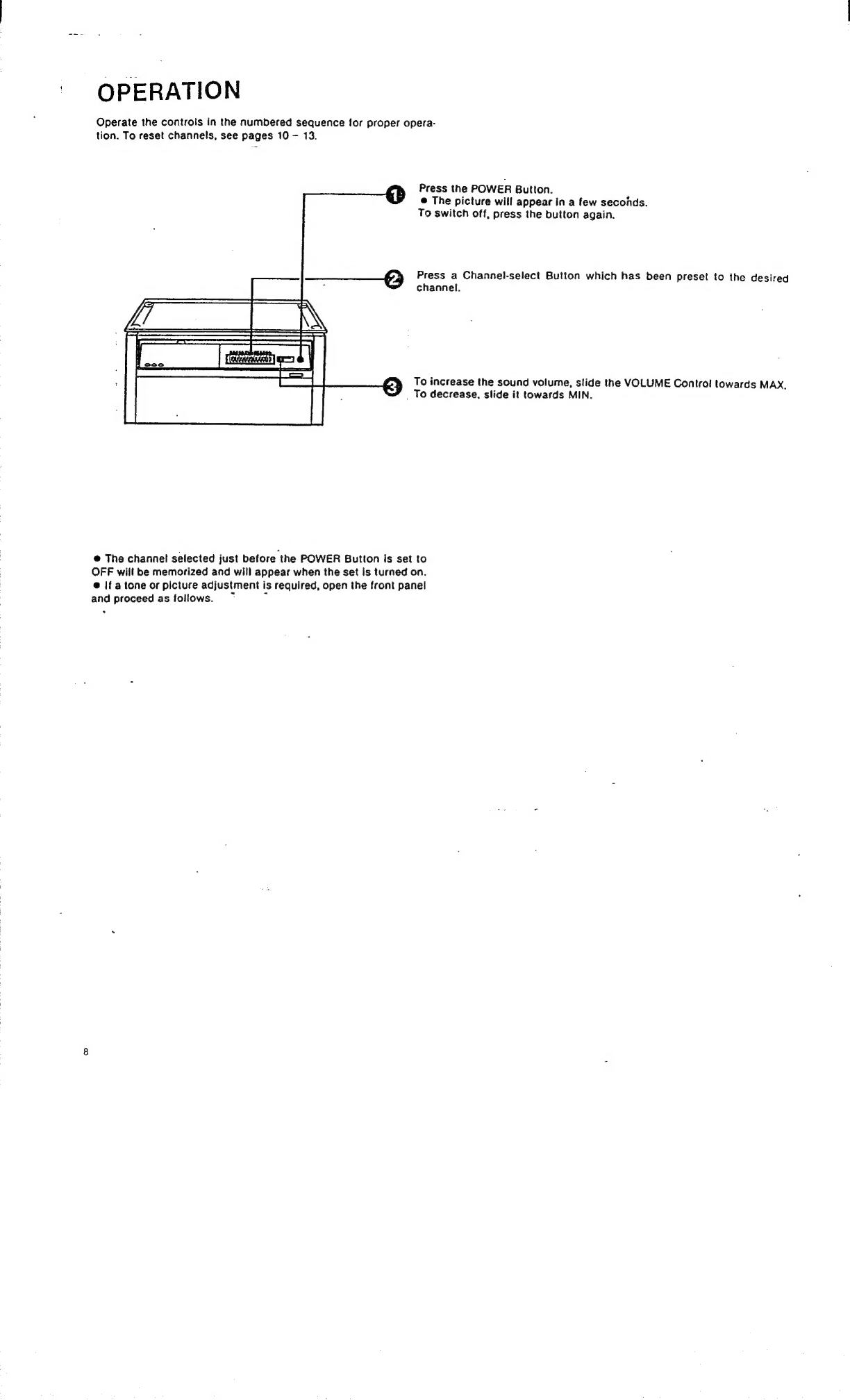
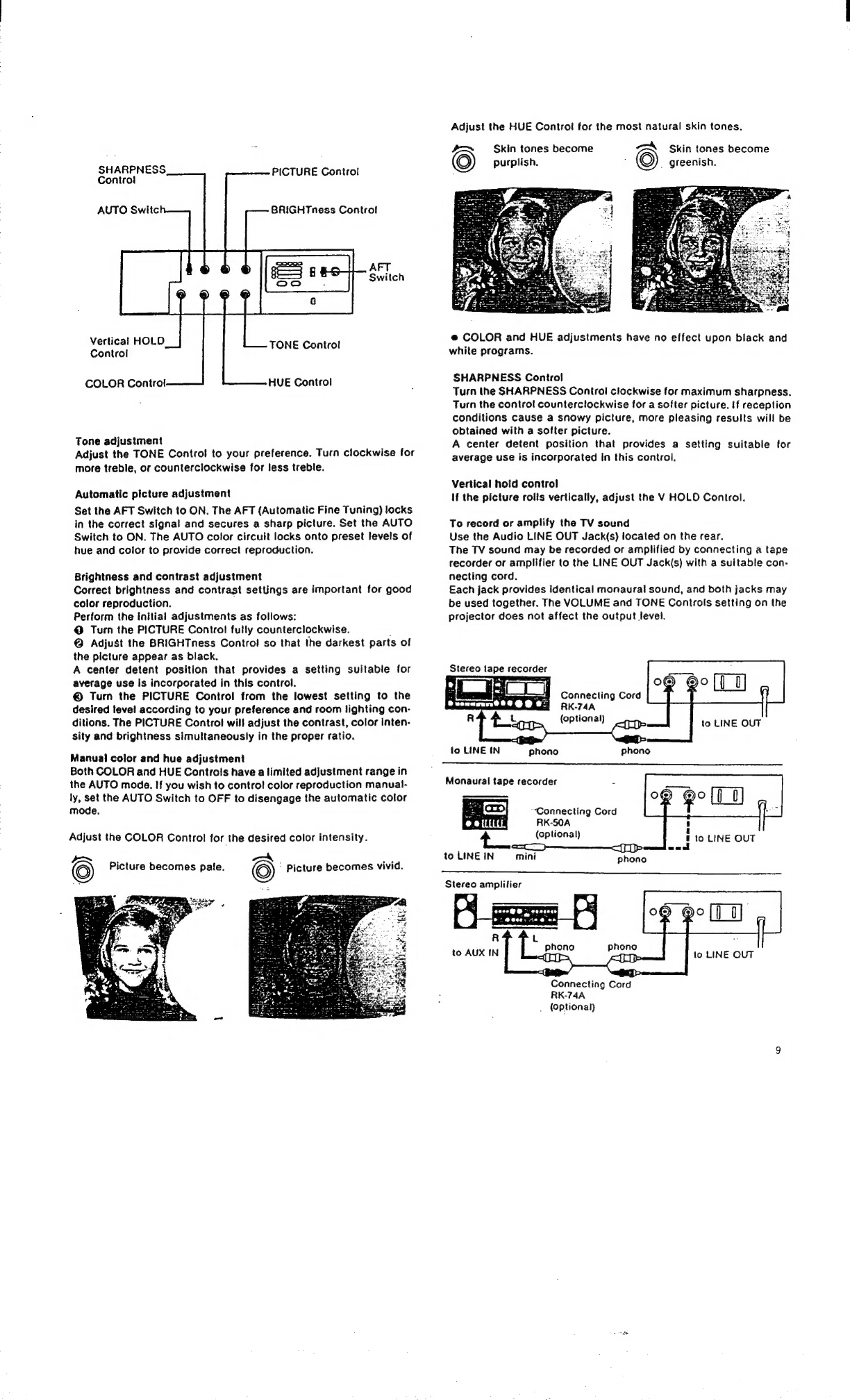
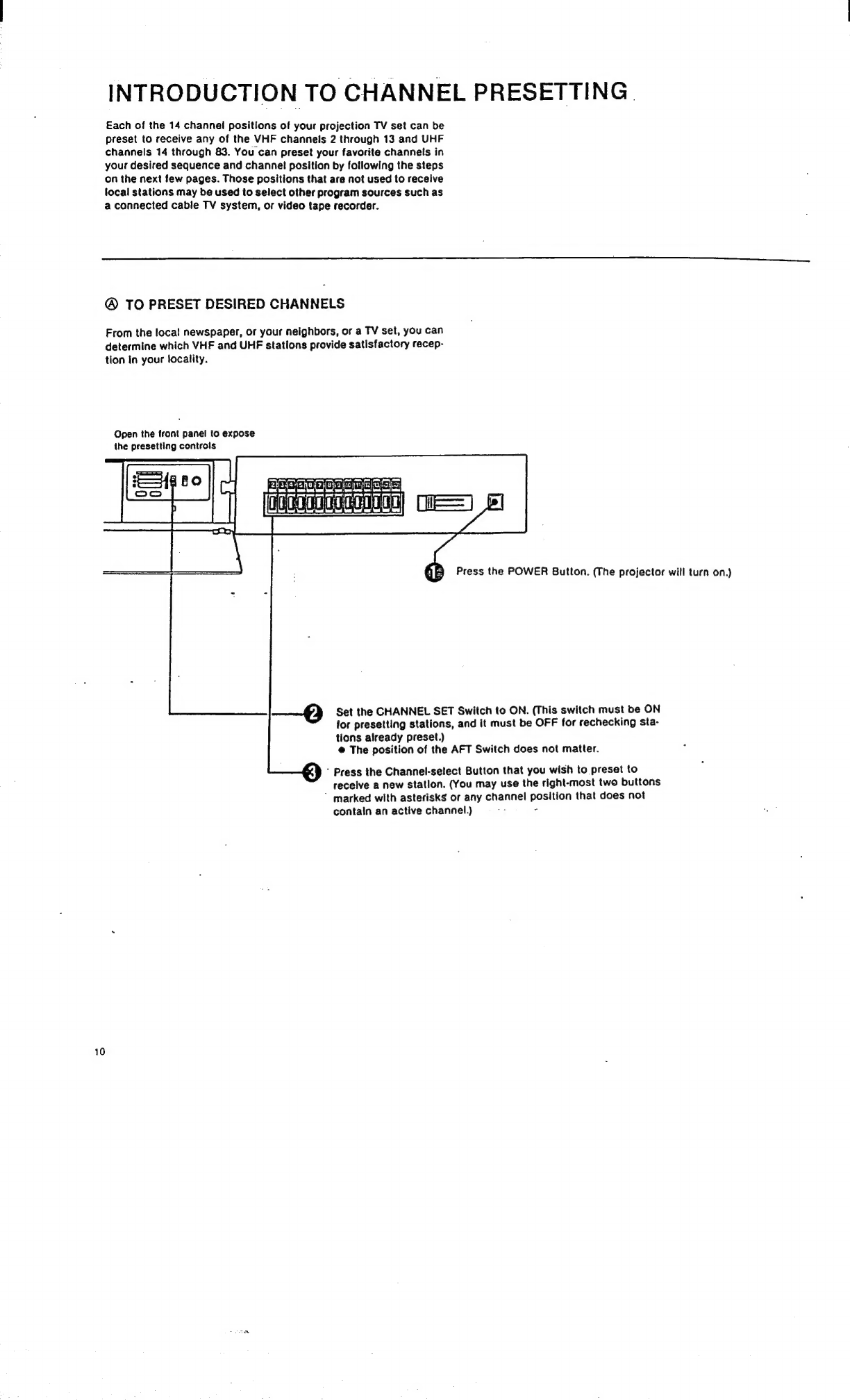
Sony KP-5020 User manual

SON
Ys,
COLOR
VIDEO
PROJECTION
SYSTEM
KP-5020/7220
OPERATING
INSTRUCTIONS
Before
operating
the
set,
please
read
this
manual!
thoroughly,
and
retain
it
for
future
reference.
Rattan
eemerpesyreremerm
efor
i
OWNER’S
RECORD.
The
model
and
serial
numbers
are
located
at
the
rear
of
the
projec-
tor.
Record
these
numbers
in
the
spaces
provided
below.
:
Refer
to
them
whenever
you
call
upon
your
Sony
dealer
regarding
this
product.
Mode!
No.
Serial
No.
©
1980
by
Sony
Corporation

WARNING
To
prevent
fire
or
shock
hazard,
do
not
ex-
pose
the
set
to
rain
or
moisture.
Dangerously
high
voltages
are
present
inside
the
projector.
Do
not
open
the
cabinet.
Refer
servicing
to
qualified
personnel
only.
CAUTION
To
ensure
top
performance,
keep
the
following
in
mind
during
in-
stallation
and
use.
Location
Do
not
Install
the
projection
system
in
a
location
near
heat
sources
such
as
radiators
or
airducts,
or
in
a
place
subject
to
direct
sunlight,
excessive
dust
or
humidity.
{Humination
The
screen
should
not
be
exposed
to
Illumination
directly
from
the
front.
Windows
that
face
the
screen
should
be
covered
by
opaque
drapery
while
the
set
Is
being
viewed.
It
Is
desirable
to
Install
the
projector
system
In
a
room
whose
walls
and
floor
are
of
nonrefiec-
ting
material.
As
a
general
rule,
darken
the
room
to
the
point
where
there
is
just
sufficlent
light
to
read
or
write
comfortably.
Spot
fighting
is
desirable
for
Illuminating
small
areas
so'that
Interference
with
the
-
screen
is
minimized.
General
:
:
@
Operate
only
on
120V
ac.
@
This
projector
Is
equipped
with
a
polarized
AC
power
cord
plug
(one
blade
of
the
plug
is
wider
than
the
othe,
which
will
fit
into
the
power
outlet
only
one
way.
Should
you
be
unable
to
insert
the
plug
fully
Into
the
outlet,
try
reversing
the
plug.
Should
the
plug
stlli
fail
to
fit,
contact
your
dealer
tor
assistance.
Do
not
defeat
the
safety
purpose
of
the
polarized
plug.
@
Allow
adequate
air
circulation
to
prevent
internal
heat
built-up.
Avoid
placing
the
projector
on
soft
surfaces
(rugs,
blankets,
etc.)
or
Inserting
magazines,
papers,
or
cloth
Into
the
space
between
the
top
board
and
the
projector
that
may
block
the
ventilation
holes.
@
Should
any
liquid
or
solid
object
fall
into
the
cabinet,
unplug
the
system
and
have
it
checked
by
qualified
personnel
before
operating
it
any
further.
@
Unplug
the
set
from
the
wall
outlet
If
It
is
not
to
be
used
for
an
extended
period
of
time.
@
To
disconnect
the
cord,
pull
It
out
by
the
plug.
Never
pull
the
cord
itself.
.
@
Avoid
touching
the
reflecting
surface
of
the
screen
or
the
lens.
To
remove
dust
on
the
screen
surface
or
lens,
use
a
dry,
soft
cloth.
Do
not
use
a
wet
cloth,
solvents,
or
thinner
for
cleaning
purposes.
@
To
keep
the
cabinet
looking
brand-new,
perlodically
clean
It
with
a
soft
cloth.
Stubborn
stains
may
be
removed
with
a
cloth
lightly
dampened
with
a
mild
detergent
solution.
Never
use
strong
solvents,
such
as
thinner
or
benzine,
or
abrasive
cleansers,
since
these
will
damage
the
cabinet.
e
Save
the
original
shipping
carton
and
packing
material;
they
will
come
in
handy
It
you
ever
have
to
ship
your
set.
For
maximum
protection,
repack
your
set
as
It
was
originally
packed
at
the
fac-
tory.
FEATURES
@
The
Sony
Color
Video
Projection
System,
2
product
of
Sony
Trinitron
color
TV
technology,
projects
TV
pictures
on
a
large
screen:
50-inch
(KP-5020)
or
72-inch
(KP-7220)
measured
diago-
nally.
@
The
projector
is
designed
to
be
used
as
a
center
table
so
as
to
permit
projector
operation
directly
from
your
seat.
@
The
semi-automatic
program
search
system
permits
easy
preset tuning
of
up
to
14
channels;
VHF,
UHF
or
Inactive
channels
(tor
monitoring
the
playback
of
a
video
tape
recorder,
etc.).
®
Advanced
new
automatic
circuits
are
built
into
the
tuner
unit
to
eliminate
the
necessity
for
frequent
readjustment
of
the
tuning
and
color
controls:
A
touch
of
the
AFT
Switch
instantly
activates
these
circults
to
tune
your
set
for
pea’
performance.
A
touch
of
the
AUTO
Switch
locks
the
color
processing
system
to
factory
preset
values
that
assure
realistic
reproduction
of
every
shade
and
tint.
@
Your
Sony
Color
Video
Projection
System
features
the
ECONO-
QUICK
system*
which
provides
a
picture
only
a
few
seconds
after
the
set
is
switched
on.
There
Is
absolutely
no
power
consumption
for
thls
feature
when
the
set
is
not
In
use.
“This
system
represents
the
latest
development
of
the
Trinitron
TV
technology.
@
Built-In
test
pattern
permits
easy
registration
adjustment.
e
Plastic
lenses
provide
a
brighter
picture
on
the
screen.

LOCATION
OF
PARTS
AND
CONTROLS
Front
CHANNEL
Indicators
VOLUME
Contro}!
POWER
Button
Top
Board
TESTINORMAL
Switch
Channel-select
Buttons
H
CENT
B
Control
Band-indicating
Lamps
VCENTB
Control
Tuning
Indicator
H
CENT
R
Control
V
CENT
R
Control
CHANNEL
SET
Switch
CHANNEL
CLEAR
Button
"Vertical
HOLD
ma
femmes
AFT
Switch
Control
-
:
ae
:
~
—
*
AUTO
Switch
eaeeneaee
=i
TUNING
Buttons
COLOR
Goi
neceeetecnel
BRIGHTness
Control
HUE
Control
-
SHARPNESS
Control
TONE
Control
PICTURE
Control
Rear
Lens
Cover
Lenses
VHF
Antenna
Terminal
Accessory
Container
Positioning
Cord
‘AC
OUTIet
UHF
Antenna
Terminals
Power
Cord
Container
Power
Cord
Audio
LINE
OUT
Jacks

PREPARATIONS
SCREEN
INSTALLATION
@
Place
the
screen
on
the
floor
with
the
screen
surface
downward.
Put
the
upper
end
of
the
screen
supports
right
on
the
upper
projections
on
the
rear
of
the
screen.
———]_
screen
support
upper
projection
@
Lift
up
the
lower
portion
of
the
screen
so
that
the
lower
projec-
tions
contact
the
screen
supports,
and
secure
with
the
two
sup-
plied
wing
screws.
Align
these
holes
and
tighten
the
wing
screw.
©
Attach
the
screen
supports
to
the
upper
projections
with
the
two
supplied
wing
screws
in
the
same
manner
as
for
the
lower
pro-
jections.
©
Raise
the
assembled
screen
and
stand
it
on
Its
feet.
POWER
CONNECTION
The
KP-5020
and
KP-7220
operate
on
120V
ac.
60
Hz.
Take
the
Power
Cord
out
of
the
Power
Cord
Container
at
the
rear
and
connect
it
to
a
120V
ac
wall
outlet.
3
to
an
ac
wall
outlet
———=—<
E>
The
AC
OUTIet
provides
a
convenient
ac
power
source
for
other
video
or
audio
equipment.
This
outlet
is
not
controtied
by
the
POWER
Button
on
the
front.
Caution:
Do
not
connect
any
electrical
home
appliance
here
such
as
an
electric
iron
or
fan
whose
power
consumption
ex-
ceeds
300
watts.

ANTENNA
CONNECTION
If
your
local
signal
is
of
adequate
strength,
an
indoor
antenna
may
be
sufficient
to
obtain
a
clear
picture.
The
use
of
an
external
antenna
Is
recommended
especiaity
in
difficult
reception
areas
(inside
steel-frame
buildings,
in
mountainous
areas,
or
at
great
distances
from
the
transmitter),
VHF
and
UHF
antennas
with
separate
lead-in
wires,
or
a
combination
VHF-UHF
antenna
with
a
single
lead-in
wire
may
be
used.
When
a
combination
VHF-UHF
antenna
Is
In
use,
the
signals,
separated
by
a
VHF-UHF
signal
splitter,
are
fed
to
the
VHF
and
UHF
terminals
of
the
projector
respectively.
Combination
VHF-UHF
antenna
VHF
antenna
UHF
antenna
La
VHF-UHF
signal
splitier
300-ohm
twin
lead
Al
©
Antenna
connector
750ohm
coaxial
cable
300-ohm
twin
lead
connector
Connection
to
the
VHF
Antenna
Terminal
When
using
a
300-ohm
ribbon-type
lead-in,
connect
the
leads
to
the
Antenna
Connector
(supplied),
then
connect
the
Antenna
Con-
nector
to
the
VHF
Antenna
Terminal.
—
©
When
using
a
75-ohm
coaxia!
cable
lead-in
from
the
antenna,
con-
nect
it
to
the
VHF
Antenna
Terminal
with
an
F-type
connector
(op-
tional).
—
©.
Connection
to
the
UHF
Antenna
Terminals
Connect
a
300-ohm
ribbon-type
lead-in
wire
to
the
UHF
Antenna
Terminals.
—@
Antenna
connector
supplied
(300-75
ohms
matching
transformer
built-in)
©
Connect
the
teads.
@
Fasten
with
a
screwdriver.
©
Plug
in.
F-type
connector
Connect
the
leads
and
tighten
the
screws.
Note:
To
view
the
playback
picture
from
a
Sony
Betamax
videocassette
recorder
(or
other
VTR)
equipped
with
an
RF
output
terminal,
con-
nect
a
suitable
antenna
to
the
recorder
(not
to
the
projector)
and
then
connect
the
VHF
(or
RF)
OUT
terminal
of
the
recorder
to
the
VHF
Antenna
Terminal!
of
the
projector.
For
details,
refer
to
the
operating
instructions
furnished
with
the
recorder.
Sony
Betamax
videocassette
recorder

SETTING
UP
THE
SYSTEM
@
Take
the
Positioning
Cord
out
of
the
Power
Cord
Container
and
connect
both
ends
of
the
cord
to
the
screen
support
feet.
SER
Lay
i
The
cord
has
been
connected
f
*s=>
to
the
bottom
rear
of
the
wy)
SS
projector.
{nsert
into
the
holes
by
pushing
downward.
connecting
pin
—=()
ef)
@
Move
the
projector
until
both
sides
of
the
cord
are
equally
ten-
sioned.
:
When
moving
the
projector,
lift
up
the
front
side
and
roll
It
on
the
casters,
72-Inch
screen
cord
length:
approx.
2183mm
50-inch
screen
[|lcord
length:
approx.
1530mm
©
Pull
out
the
connecting
pins
to
remove
the
Positioning
Cord
from
the
screen
support
feet.
Store
the
Positioning
Cord
in
the
Ac-
cessory
Container
or
the
Power
Cord
Container.
©
Put
the
Top
Board
(made
of
tempered
glass)
on
the
Projector.
The
projector
may
thus
be
used
as
a
center
table,
Although
the
tempered
glass
is
more
shock-resistant
than
ordinary
glass,
it
may
shatter
if
it
receives
a
sudden
shock.
®
Be
careful
not
to
hit
the
edge
of
the
glass
with
any
object.
@
Do
not
drop
anything
on
the
glass.
@
Be
carefu!
not
to
scratch
the
glass.
©
Remove
the
Lens
Cover.
Note:
@
The
projector
and
the
screen
should
be
located
on
the
same
horizontal
level.
Avoid
setting
them
on
a
slanting
floor.
When
placing
the
projector
or
the
screen
on
an
uneven
floor,
turn
counterclockwise
the
rubber
feet
on
the
bottom
front
of
the
pro-
jector
or
on
the
bottom
of
the
screen
supports
until
the
set
is
level.
@
The
projector
and
the
screen
should
be
Installed
perpendicular
to
each
other.
(This
can
be
checked
in
the
following
registration
adjustments.)
Audience
area
D-inch
streen
viewing
distance
3.0
m
(10
ft)/to
18.3
m
(60
ft)
3.6
m
(12
ft)lto
24.4
m
(80
ft)

REGISTRATION
ADJUSTMENT
Preparation
@
Open
the
front
panel
and
remove
the
cover
to
expose
the
con-
trots.
Push
the
feft
side
and
remove.
©®
Set the
TEST/NORMAL
Switch
to
TEST.
©
Press
the
POWER
Button
to
switch
on
the
projector.
A
built-in
test
pattern
will
be
displayed
on
the
screen.
@
Check
that
the
white
vertical
line
is
displayed
at
the
horizontal
_
center
of
the
screen.
If
it
is
not,
move
the
right
or
left
side
of
the
projector
slightly
to
center
the
line
(to
install
the
projector
perpen-
dicular
to
the
screen).
Use
the
SONY;
emblem
as
a
center
mark.
Adjustment
After
transporting
the
set
from
one
place
to
another,
the
red,
green
and
blue
lines
may
not
be
superimposed
(the
cross
may
not
be
seen
as
white).
:
If
this
symptom
is
noticed,
perform
the
registration
adjustment
yourself.
Should
the
difficulty
persist,
contact
your
Sony
dealer.
As
you
turn
the
controls
clockwise,
the
lines
move
in
the
direction
Indicated
in
the
itlustrations.
To
move
the
lines
in
the
opposite
direction,
turn
the
controls
counterclockwise.
@
Adjust
the
H
CENT
B
and
H
CENT
A
Controls
to
converge
the
blue
and
red
vertical
lines
with
the
green
line.
©
Adjust
the
V
CENT
B
and
V
CENT
R
Controls
to
converge
the
blue
and
red
horizontal
lines
with
the
green
line.
yellow
cyan
(G
and
A)
(G
and
B)
V
CENT
B
VCENTR
©
Repeat
steps
@
and
@
until
the
cross
appears
white.
©
After
the
adjustment
is
completed,
set
the
TEST/NORMAL
Switch
to
NORMAL,
replace
the
cover,
and
close
the
tront
panel.

OPERATION
Operate
the
controls
in
the
numbered
sequence
for
proper
opera-
tion.
To
reset
channels,
see
pages
10
-
13.
Press
the
POWER
Button.
®
The
picture
will
appear
in
a
few
secohds.
To
switch
off,
press
the
button
again.
Press
a
Channel-select
Button
which
has
been
preset
to
the
desired
channel.
To
increase
the
sound
volume,
slide
the
VOLUME
Control
towards
MAX.
To
decrease,
slide
it
towards
MIN.
@
The
channel
selected
just
before
the
POWER
Button
is
set
to
OFF
will
be
memorized
and
will
appear
when
the
set
is
turned
on.
@
If
atone
or
picture
adjustment
is
required,
open
the
front
panel
and
proceed
as
follows.

SHARPNESS
PICTURE
Control
Control
AUTO
Switc
8RIGHTness
Control
AFT
Switch
Vertical
HOLD
Control
TONE
Control
COLOR
Control
HUE
Control
Tone
adjustment
Adjust
the
TONE
Control!
to
your
preference.
Turn
clockwise
for
more
treble,
or
counterclockwise
for
less
treble.
Automatic
picture
adjustment
Set
the
AFT
Switch
to
ON, The
AFT
(Automatic
Fine
Tuning)
locks
in
the
correct
signal
and
secures
a
sharp
picture.
Set
the
AUTO
Switch
to
ON.
The
AUTO
color
circuit
locks
onto
preset
levels
of
hue
and
color
to
provide
correct
reproduction.
Brightness
and
contrast
adjustment
Correct
brightness
and
contrast
settings
are
important
for
good
color
reproduction.
Perform
the
initial
adjustments
as
follows:
@
Turn
the
PICTURE
Control
fully
counterclockwise.
;
@
Adjust
the
BRIGHTness
Control
so
that
the
darkest
parts
of
the
picture
appear
as
black,
A
center
detent
position
that
provides
a
setting
suitable
for
average
use
Is
incorporated
in
this
control.
©
Turn
the
PICTURE
Control
from
the
lowest
setting
to
the
desired
level
according
to
your
preference
and
room
lighting
con-
ditions.
The
PICTURE
Control
will
adjust
the
contrast,
color
inten-
sity
and
brightness
simultaneously
in
the
proper
ratio.
Manual
color
and
hue
adjustment
Both
COLOR
and
HUE
Controls
have
a
limited
adjustment
range
in
the
AUTO
mode.
If
you
wish
to
control
color
reproduction
manual!-
ly,
set
the
AUTO
Switch
to
OFF
to
disengage
the
automatic
color
mode.
Adjust
the
COLOR
Control
for
the
desired
color
intensity.
Picture
becomes
pate.
Picture
becomes
vivid.
Adjust
the
HUE
Contro!
for
the
most
natural
skin
tones.
Skin
tones
become
=
purplish.
ss
skin
tones
become
©).
greenish.
@
COLOR
and
HUE
adjustments
have
no
effect
upon
black
and
white
programs.
SHARPNESS
Control
Turn
the
SHARPNESS
Control
clockwise
for
maximum
sharpness.
Turn
the
control
counterctockwise
for
a
softer
picture.
If
reception
conditions
cause
a
snowy
picture,
more
pleasing
results
will
be
obtained
with
a
softer
picture.
A
center
detent
position
that
provides
a
setting
suitable
for
average
use
is
incorporated
in
this
control.
Vertical
hold
control
If
the
picture
rolls
vertically,
adjust
the
V
HOLD
Control.
To
record
or
amplify
the
TV
sound
Use
the
Audio
LINE
OUT
Jack(s)
located
on
the
rear.
The
TV
sound
may
be
recorded
or
amplified
by
connecting
a
tape
recorder
or
amplifier
to
the
LINE
OUT
Jack(s)
with
a
suitable
con-
necting
cord.
Each
jack
provides
identical
monaural
sound,
and
both
jacks
may
be
used
together.
The
VOLUME
and
TONE
Controls
setting
on
the
projector
does
not
affect
the
output
level.
Stereo
tape
recorder
=a
Connecting
Cord
RK-74A
(optional)
Connecting
Cord
RK-50A
(optional)
to
LINE
IN
mini
Stereo
amplifier
Connecting
Cord
RK-74A
;
(optional)

INTRODUCTION
TO
CHANNEL
PRESETTING.
Each
of
the
14
channel
positions
of
your
projection
TV
set
can
be
preset
to
receive
any
of
the
VHF
channels
2
through
13
and
UHF
channels
14
through
83.
You
can
preset
your
favorite
channels
in
your
desired
sequence
and
channet
position
by
following
the
steps
on
the
next
few
pages.
Those
positions
that
are
not
used
to
receive
tocal
stations
may
be
used
to
select
other
program
sources
such
as
a
connected
cable
TV
system,
or
video
tape
recorder.
®
TO
PRESET
DESIRED
CHANNELS
From
the
loca!
newspaper,
or
your
neighbors,
or
a
TV
set,
you
can
determine
which
VHF
and
UHF
stations
provide
satisfactory
recep-
tion
in
your
locality.
Open
the
tront
panel
to
expose
the
presetting
controls
Press
the
POWER
Button.
(The
projector
will
turn
on.)
Set
the
CHANNEL
SET
Switch
to
ON.
(This
switch
must
be
ON
tor
presetting
stations,
and
it
must
be
OFF
for
rechecking
sta-
tlons
already
preset.)
@
The
position
of
the
AFT
Switch
does
not
matter.
’
Press
the
Channel-select
Button
that
you
wish
to
preset
to
receive
a
new
Statlon.
(You
may
use
the
right-most
two
buttons
*
marked
with
asterisks
or
any
channel
position
that
does
not
contain
an
active
channel.)
-

x.
UHF
Channel
41
4
.
C2
VE 6)
Tuning
Indicator
and
Band
Indicator
Lamps
ig
The
red
famp
when
fIt
shows
you
are
In
the
Band
including
channels
2
through
6,
the
yellow
lamp
when
lft
shows
you
are
in
the
band
Including
channels
7
through
13,
and
the
green
lamp
when
lit
shows
you
are
in
the
band
Including
chan-
nels
14
through
83.
Within
each
of
these
bands,
stabilize.
again.
above)
as
guides.
preset.
now
set
to
ON.
After
the
presetting
has
been
completed,
replace
the
Channel
In-
dicating
Segments
to
correspond
to
yéur
presetting
(see
page
13)
and
close
the
front
panel.
@
If
there
Is
a
VTR
position
to
be
included,
refer
to
page
13.
@
To
use
your
projection
system
with
a
cable-television
system,
contact
a
representative
of
the
cable
company
for
Instructions
regarding
channel
selection.
In
most
cases,
this
adjustment
will
be
made
by
the
cable
company
at
the
time
of
installation.
Press
‘the
TUNING-up
>
of
-down
<
Button.
(Do
not
hold
the
button
in,
just
press
It
momentartly).
Allow
1
or
2
seconds
for
the
picture
to
the
multi-segment
Tuning
Indicator
will
show
In
what
portion
of
the
band
you
are
tuned
to
atany
:
given
moment,
with
the
left-most
segment
in-
dicating
the
lowest
frequency
within
each
bana,
and
the
right-most
segment
indicating
the
highest
frequency
within
each
band.
:
@
In
strong
signal
areas,
tuning
may
sometimes
stop
between
channels.
‘If
a
station
Is
not
recelved,
press
the
TUNING-up
p>
or-down
<q
Button
Repeat
step
CG]
as
required
until
your
desired
station
appears
on
the
screen.
Use
the
Tuning
indicator
and
Band
Indicator
Lamps
(explained
Repeat
steps
8,
44)
and
5)
for
all
the
channel
positions
you
wish
to
Set
the
CHANNEL
SET
Switch
to
OFF
and
make
sure
the
AFT
Switch
is
11

TO
ARRANGE
THE
ACTIVE
VHF
AND
UHF
CHANNELS
IN
NUMERICAL
SEQUENCE
OR
YOUR
DESIRED
SEQUENCE
-
Any
push
button
can
be
set
to
any
frequency
from
below
channel
2
to
the
highest
UHF
TV
frequency.
@
Make
a
list
of
your
receivable
VHF
and
UHF
stations
and
list
them
as
shown
in
the
following
example.
VHF:
Channels
2,
4,
5,
7,
9,
11
and
13
UHF:
Channels
21,
25,
31,
41
and
47
@
Having
made
such
a
list,
remove
the
Channel
Indicator
Sheet
from
the
panel,
and
insert
numbers
to
correspond
to
your
list
(in-
structions
on
changing
numbers
are
on
page
13).
You
are
now
ready
to
preset
the
Channel-select
Button
to
correspond
to
your
selection
of
stations.
Example
12/4]5}
7]
9[1i)13[2qas[3i]afaz]-<]
©
Press
the
POWER
Button,
(the
projector
will
turn
on).
©
Set
the
CHANNEL
SET
Switch
to
ON
(This
switch
must
be
ON
for
presetting
stations,
and
it
must
be
OFF
for
rechecking
stations
already
preset).
©
Press
the
Channet-select
Button
to
be
Preset
first.
The
station
selected
just
before
the
CHANNEL
SET
Switch
had
been
set
to
ON
will
appear
on
the
screen
(the
channels
may
be
preset
in
any
order,
however,
it
is
more
convenient
to
start
with
the
lowest
channel
number
and
proceed
to
the
highest
channel
number
when
chan-
nels
are
placed
in
ascending
numerical
order).
@
In
our
example
above,
We
would
start
by
pressing
the
Channel-
select
Button
marked
4,
sifice
channel
2
has
already
been
preset
at
the
factory.
To
fine-tune
the
channel
manually
In
case
of
extreme
interference,
or
of
an
extremely
weak
sta-
tion,
adjust
the
fine
tuning
manually
as
follows.
Blurred
Clear
Adjacent
No
color
picture
TV
station
No
picture
Press
the
>»
Button.
12
eee
coli
ee
@
Using
the
Tuning
Indicator
and
Band
Indicator
Lamps
(expiain-
ed
in
section
@),
press
the
TUNING-up
>
Button
for
locating
higher
numbered
channels
or
the
TUNING-down
<q
Button
for
locating
lower
numbered
channels.
(Do
not
hold
the
button
In,
just
press
it
momentarily).
Allow
1
or
2
seconds
for
the
picture
to
stabilize.
@
Repeat
step
@
,
as
required
until
your
desired
station
ts
receiy-
ed.
@
In
strong
signal
areas,
tuning
may
sometimes
stop
between
channels.
If
your
desired
station
cannot
be
received,
press
the
TUNING
Button
again.
©
Press
the
next
Channel-select
Button
to
be
preset
and
press
the
TUNING-up
»
or
TUNING-down
<q
Button
as
required
to
locate
the
next
station.
@
In
our
example
we
would
now
press
the
next
Channet-select
‘Button
to
the
right
(marked
5)
and
press
the
TUNING-up
>
But-
ton
to
receive
the
next
higher
station.
©
Repeat
step
©
until
all
desired
stations
have
been
preset.
@
Set
the
CHANNEL
SET
Switch
to
OFF
and
make
sure
that
the
AFT
Switch
is
now
set
to
ON.
Alternative
Tuning
Method
Before
tuning
in
the
desired
station,
you
may
use
the
CHANNEL
CLEAR
Button
to
erase
any
memory
on
the
depressed
Channel-
select
Button,
and
to
position
Its
tuning
to
a
frequency
below
channel
2.
Then
use
the
TUNING-up
>
Button
as
often
as
re-
quired
to
locate
your
desired
station.
Check
that
the
CHANNEL
SET
Switch
is
set
to
OFF,
set
the
AFT
Switch
to
OFF
and
keep
the
TUNING-up
P
or
TUNING-
down
<
Button
depressed
until
a
clear
picture
is
obtained.
Refer
to
the
following
chart.
;
When
the
fine
tuning
is
completed,
close
the
front
panel
with
AFT
Switch
set
to
off.
Herringbone
5
r
Adjacent
pattern
Distoned
No
picture
TV
station
|
Press
the
<4
Button.

CHECKING
THE
SET
BY
YOURSELF
through
this
illustrated
list
of
symptoms
and
corrections.
Should
the
difficulty
persist,
unpiug
the
set
and
contact
your
Sony
dealer.
Many
apparent
maitunctions
may
be
caused
by
slight
misadjust-
ments
of
the
regular
controls
or
some
other
equally
simple
cause.
If
any
difficulty
arises
in
the
operation
of
your
set,
first
check
CORRECTION
SYMPTOM
no
picture
(screen
not
lit)
no
sound
@
Plug
the
set
into
a
work-
ing
outlet.
no
picture
(screen
not
lit),
but
good
sound
@
Turn
the
BRIGHThness
or
PICTURE
Control
clock-
wise.
good
picture
but
no
sound
@
Slide
the
VOLUME
Con-
trol
toward
MAX.
no
picture,
no
sound,
but
snow
and
noise
only
|
@
Connect
the
antenna
properly.
@
Check
the
outdoor
antenna.
14
SYMPTOM
CORRECTION
@
Set
the
AUTO
Switch
to
ON.
no
color
‘|
@
Set
the
AFT
Switch
to
ON.
@
Turn
the
COLOR
Control
clock:
wise.
herringbone
pattern,
stripes,
@
Set
the
AFT
Switch
to
OFF
and
no
color,
adjust
the
fine
tuning
with
the
TUNING-up
PD
or
TUNING-down
no
picture,
<4
Button.
too
indistinct,
etc.
picture
out
of
|
@
Check
the
system
set-up
and
focus,
blurred
|
registration
referring
to
pages
6
-
color
7.
@
Olten
caused
by
Interference
from
autos,
neon
signs,
hair
dryers,
electric
razors,
etc.
Try
adjusting
the
antenna
for
minimum
iIn-
terference.
dotted
lines
or
stripes
@
Readjust
the
indoor
antenna.
Reflections
from
nearby
mountains
double
images}
or
buildings
often
cause
this pro-
or
“ghosts”
blem.
In
such
cases,
a
highly
direc:
tional
outdoor
antenna
may
Im-
prove
the
picture.

To
replace
the
number-indicating
segment
@
Remove
the
Channel
Indicator
sheet.
@®
Press
the
segment
out
from
the
rear.
©
Replace
the
sheet
in
the
original
position.
To
preset
for
VTR
playback
Al
the
factory,
the
second
button
from
the
feft
is
preadjusted
to
VHF
channel
3,
and
the
third
button
to
VHF
channel
4.
One
of
these
channels,
3
or
4,
is
locally
inactive
and
may
be
used
to
view
the
playback
picture
from
a
Sony
Betamax
videocassette
recorder
(or
other
VTR)
equipped
with
an
RF
output
terminal.
If
you
wish
to
preset
some
other
position
to
receive
the
signals
from
the
recorder,
complete
the
connections
and
proceed
as
follows.
@
Set
the
recorder
to
the
playback
mode.
The
signal
from
the
recorder
will
be
fed
to
the
projector.
@
Set
the
CHANNEL
SET
Switch
to
ON.
©
Press
the
Channet-select
Button
to
be
preset
for
viewing
the
playback
picture.
©
Press
the
CHANNEL
CLEAR
Button.
©
Press
the
TUNING-up
>
Button
until
VHF
channel
3
or
4
(the
Operating
channel
of
the
cf
unit
built
into
the
recorder)
is
received,
whereupon
a
clear
picture
will
be
obtained.
@
Set
the
CHANNEL
SET
Switch
to
OFF.

TECHNICAL
SPECIFICATIONS
3
picture
tubes,
3
lenses
horizontal
In-line
system
5.$-inch
high-brightness
monochrome
tubes
F1.0/130mm
plastic
lenses
Aluminum
foil
concave
screen
Projection
system
Picture
tube
Projection
lens
Screen
materlal
KP-5020
Projected
picture
size
(measured
diagonally)
Audlence
area
|
Viewlng
distance
50
inches
72
inches
3.6
m
(12
ft)
mini-
mum
to
24.4m
(80
ft)
maximum
3.0
m
(10
ft)
mini-
mum
to
18.3
m
(60
ft)
maximum
|
Optimum
seating
arrangement
Throwing
distance
Within
approx.
45
degrees
from
center
Approx.
1.8
m
(6
ft)
|[Approx.
2.5
m
(8
ft)
American
TV
standards
VHF
channels
2-13
UHF
channels
14-83
{a
total
of
up
to
14
preselected
channels)
75-ohm
antenna
terminal
for
VHF
300-ohm
antenna
terminals
for
UHF
2
speakers,
10
cm
(4
Inches)
dia.
LINE
OUT
(2
phono
Jacks)
~5
dB,
approx.
10
kilohms
Power
requirements
120V
ac,
60
Hz
Power
consumption
130W
(max),
100W
(average)
Dimensions
Projector
Approx.
830
x
424
x
650
mm
(wihid)
32%
x
16%
x
25%
inches
incl.
projecting
parts
and
controls
Screen
See
the
figure.
Projector
Approx.
53
kg
(116
Ib
14
02)
incl.
tap
board
of
13
kg
(28
Ib
11
02)
KP-5020:
Approx.
8.9
kg
(19
Ib
10
02)
KP-7220:
Approx.
17.2
kg
(37
Ib
13
oz)
incl.
screen
supports
|
Channel
number
segments
Antenna
connector
(300-75
ohm
matching
transformer
is
;
built-in)
Television
system
Channel
coverage
Antenna
Speaker
Audio
output
Welght
Screen
Accessories
suppiled
Design
and
specifications
subject
to
change
without
notice.
KP-5020
screen
f
1098
(43%
|
1020
(40°)
dimensions
sz
=
N
Me)
2
©
w
o
ag
700
(27%)
KP-7220
screen
dimensions
1608
(63%)
1468
(57%)
402(15%)
eae
758
(29718
unit:
mm
(inches)
15
This manual suits for next models
1
Table of contents
Other Sony Projector manuals

Sony
Sony VPL-ES1 User manual

Sony
Sony VPL-VW350ES User manual

Sony
Sony S1800Q User manual

Sony
Sony SuperData VPH-1251Q User manual

Sony
Sony VPL VPL-HW15 User manual

Sony
Sony VPL-SW125 User manual

Sony
Sony BRAVIA VPL-HW15 User manual

Sony
Sony SuperLite VPL-CS7 User manual

Sony
Sony VPL-V W100 User manual

Sony
Sony VPL-CX70 User manual