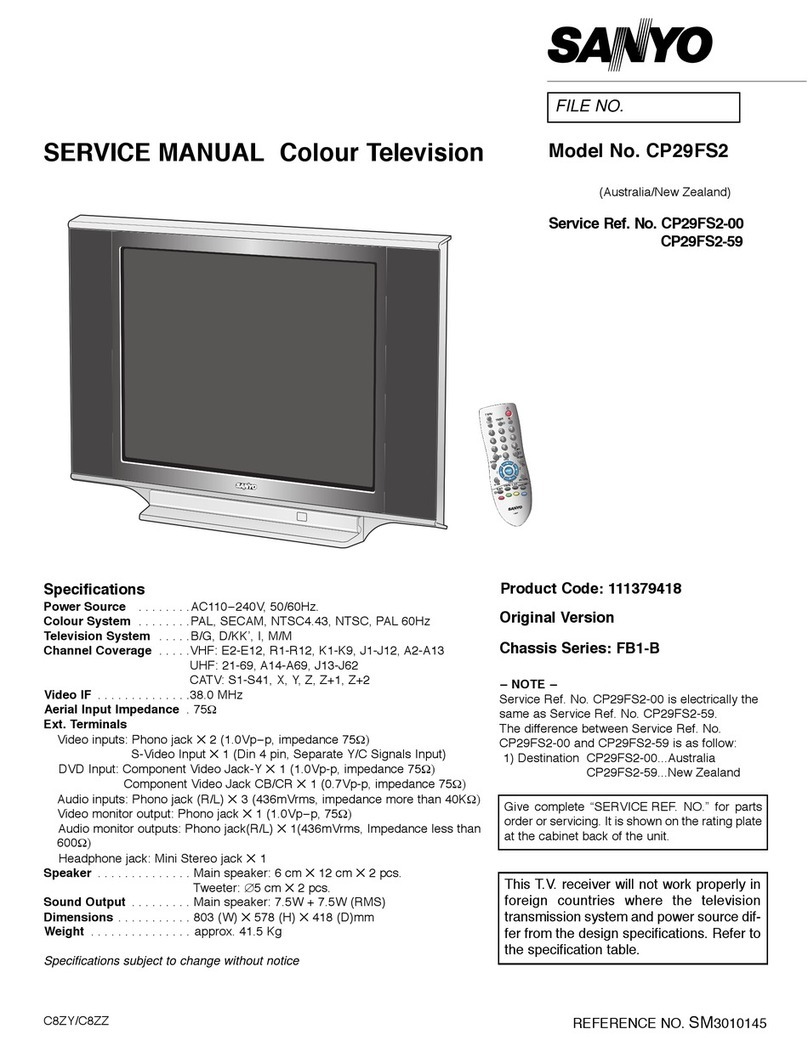
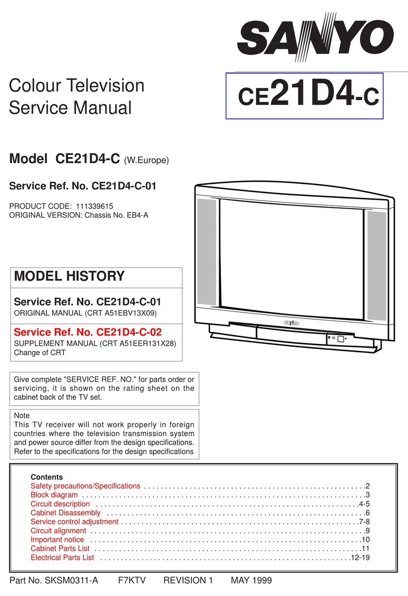
Sanyo CE32FWH2F-C User manual

Part No. SKSM0674 C6BLL SEPTEMBER 2003
Colour Television
Service Manual
Model CE32FWH2F-C
Service Ref. No. CE32FWH2F-C-00
PRODUCT CODE: 111366110
ORIGINAL VERSION: Chassis No. WB6-A
Give complete "SERVICE REF. NO." for parts
order or servicing, it is shown on the rating sheet
on the cabinet back of the TV set.
Note
This TV receiver will not work properly in foreign
countries where the television transmission
system and power source differ from the design
specifications. Refer to the specifications for the
design specifications
CE32FWH2F-C
Contents
Safety precautions/Specifications ..................................................................................................................2
Block diagrams ..............................................................................................................................................3
Cabinet Disassembly......................................................................................................................................4
Adjustment and Repair Procedures............................................................................................................5~9
CPU Port Functions......................................................................................................................................10
IC Block Diagrams ..................................................................................................................................11~13
Pin description of semiconductors................................................................................................................14
Part Description and reading of schematic diagram ....................................................................................15
Cabinet Parts List ........................................................................................................................................16
Electric Parts List....................................................................................................................................17~26
Please use Schematic Diagram SKP20398 with
this Service Manual.

-2-
C6BLL
VHF:
E2-E12, F2-F10,
R1~R12
.
SAFETY PRECAUTION
X-RADIATION PRECAUTION
The primary source of X-RADIATION in the television receiver is the picture tube. The picture tube is specially
constructed to limit X-RADIATION emissions. For continued X-RADIATION protection, the replacement tube
must be the same type as the original including suffix letter. Excessive high voltage may produce potentially
hazardous X-RADIATION. To avoid such hazards, the high voltage must be maintained within specified limit.
Refer to this service manual, high voltage adjustment for specific high voltage limit. If high voltage exceeds
specified limits, take necessary corrective action. Carefully follow the instructions for +B1 volt power supply
adjustment, and high voltage adjustment to maintain the high voltage within the specified limits.
PRODUCT SAFETY NOTICE
SPECIFICATIONS
Product safety should be considered when a component replacement is made in any area of a receiver.
Components indicated by mark in the parts list and the schematic diagram designate components in which
safety can be of special significance. It is particularly recommended that only parts designated on the parts list in
this manual be used for component replacement designated by mark . No deviations from resistance wattage
or voltage ratings may be made for replacement items designated by mark .
!
!
!
1: An isolation transformer should be connected in the
power line between the receiver and the AC line
when a service is performed on the primary of the
converter transformer of the set.
2: Comply with all caution and safety-related notes
provided on the cabinet back, inside the cabinet, on
the chassis or the picture tube.
3: When replacing a chassis in the cabinet, always be
certain that all the protective devices are installed
properly, such as, control knobs, adjustment covers
or shields, barriers, isolation resistor-capacitor networks
etc. Before returning any television to the customer,
the service technician must be sure that it is completely
safe to operate without danger of electrical shock.
Power source AC 220~240V, 50Hz
Television system System B/G, I, D/K, L/L’
Colour system PAL/NTSC4.43 (PAL/NTSC4.43/NTSC3.58 IN AV MODE)
Receiving channel UHF: 21~69
VHF: E2-E12, F2-F10, R1-R12.
CATV: X, Y, Z, S1-S41, B-Q.
Aerial input impedance 75ohm
Rear AV terminal
AV1: CENELEC standard
INPUT: Composite video, RGB and Audio L/R
OUTPUT: TV-output with composite video and audio L/R
AV2: CENELEC standard
INPUT: Composite video, RGB, S-VHS and Audio L/R
OUTPUT: Monitor output with composite video and Audio L/R
Front AV terminal
AV3: RCA jacks
INPUT: Composite video and Audio L/R
Sound output(Music) 12 x 2
Dimensions (WxHxD) 880 x 575 x 549mm
Weight 48.5 Kg
-3- C6BLL
BLOCK DIAGRAM
This is a diagram for all models and therefore differs slightly from the actual block diagram.
WB6A BLOCK DIAGRAM FM-mono/AM TV Audio Processor SIGNAL
SIF(A2/NICAM) Digital Sound Demodulator
STV8216TP FRONT
<9V>
<3.3V> SCART
<1.8V> SCART-1 AV-IN/OUT(TV-Out)
RGB
SCART-2 AV-IN/OUT(Monitor-Out)
Y/C-IN
RGB
<9V>
FRONT-AV
Monitor-Out AV-IN
<5V>
TUNER
<5V> <1.8V> Digital Video Decoder <5V>
<3.3V>
POW&DEF
YCrCb[7:0](8wires) V-Out
<9V> LA7846N
<3.3V> R/Pr
<1.8V> G/Y V+/-
B/Pb
27MHz TDA9330H <HOP> H-Out
Integrated Up-Converter H-OUT
IICBUS with 32bit CPU Core RGB PROCESSOR
DEF PROCESSOR
2H
<3.3V> 2V EW-OUT
EEPROM Pcc Cont
<3.3V> FLASH SDRAM <3.3V> IK R/G/B RGB DRIVE
M29W160DT HY57V281620HCT-H
CRT
VIF& SIF
TDA9886/V
SAW
STV2310
STV350
0
DY
TDA6108J CRT
H-syn
c
V-sync
C
LK DAT
AudioAmp
TDA7263M SP
TV-Out
CVBS
/
Y
R/G/B
C
VIDEO SW
BA7615N
CLKXTM
CLKXTP
RGB SW
TC4053
(12
(1
(8
VIF
SIF
(78
)
(73
)
(28/2
9
(1 (4)
(6
(8
)
(10
(2) (3
)
(51/52/5
3
(33)(3
4
(15)(14
(154)
(155)
(153)
(31 (4
3
(42)
(116 (109)(11
0
(44)
(40
(41
(42 (3)
(1)(2)
(8)
(24)
(23)
(159
)
(158
)
(26)(28)(27
(9)
(10)
(14
)
(15
)
(23)
(24)
(18)
(19) (1)
(2)
(12)
(2)
(5)
(13)
(1)
(3)
(14)
(15)
(4)
(1)(
5
(8
(10
(5)

-4-
C6BLL
CABINET DISASSEMBLY
CABINET BACK DISASSEMBLY
1. Remove 11 screws(A) for 32”
2. Pull out the cabinet back.
A A AA
A
A
A
A
A
A
A

-5- C6BLL
OPTION SETTING
[After replacing the Memory IC (IC803)]
The memory IC, IC803, stores the option data of TV set and service adjustments data for each circuit, therefore,
when the memory IC is replaced, it should be performed following setting and “SERVICE ADJUSTMENT” on next
page.
To enter to the Option Mode
+ Press and hold the F/OK button on the remote control and P▼button on the front panel of the TV. The option
window will appear on the screen.
To set the option mode
+ Highlight the desired option item by using the P▲or P▼ button .
+ To switch the option mode, use the Volume - (LEFT) or Volume + (RIGHT) button.
+ The data which is set in the option mode is stored into the memory IC automatically.
Following table shows the available option items and default setting mode.
Exit from the Service Mode
+ Press the MENU button.
Option Mode Mode Description & Note
ON-TIMER ON or OFF On-timer available, default “ON”
PLUG AND PLAY ON or OFF Plug and Play mode, default “ON”
WELCOME TEXT ON or OFF Display message when first set up, default “ON”
BBE ON or OFF BBE sound mode, default “OFF”
AUTO VOLUME OFF or ON Default “OFF”
HEADPHONE ON or OFF Headphone control , default “OFF”
CRT 16:9 MODE ON or OFF Default “ON”
NOISE REDUCTION ON or OFF Default “OFF”
COUNTRY UK, IRE TV system, default “UK”
BG/DK / I / LL’
ON-TIMER ON
PLUG AND PLAY ON
WELCOMETEXT ON
BBE OFF
AUTOVOLUME OFF
HEADPHONE OFF
CRT 16:9 MODE ON
NOISE REDUCTION OFF
COUNTRY UK
OPTION MODE FOR CE32FWH2F-C-00

-6-
C6BLL
SERVICE ADJUSTMENTS
INITIALISATION OF MEMORY IC
To initialise the memory IC (IC803), press and hold the NORMAL button on the remote control, then press the
P▼button on the front panel of the TV set and then turn the Mains switch Off and On. The initialisation is now
completed.
When initialised the memory IC and all of the setting data (option data and service adjustment data) stored in the IC
are reset to the default value. It is necessary to set the option settings and readjust the service adjustments listed on
page 6 and to re-tune all the channels.
The available adjustment items are as follows;
TDA9885 : This can be adjusted for AGC.
Image : This can be adjusted for picture images/shapes.
Video : This can be adjusted for the service adjustment.
DO NOT ADJUST OTHER SETTINGS
[After replacing the Memory IC (IC803)]
The memory IC, IC803, stores the service adjustments data for each circuit, therefore, when the memory IC is
replaced, it should be programmed by using “OPTION SETTING” on previous page and the following adjustments.
While pressing the green button on the remote control press the P▼ on the cabinet front. The service menu
appears.
Use the P▼ or P▲ to highlight the service menu you require and press the F/OK button to enter.
Press the Menu button to navigate backwards through the service menus until menus disappear.
IMPORTANT NOTICE
Do not attempt to adjust service adjustments not listed on the above otherwise it may cause
loss of performance and product safety.
Note: Some items of the service adjustments for this chassis are controlled by the CPU, IC801, and the
adjustments are carried out by using the RC handset.
TO ENTER SERVICE ADJUSTMENTS
TO EXIT SERVICE ADJUSTMENTS
Service
SW Vers 1.2.0
Video
Sound
STV2310
TDA9885
STV8206
TDA9330
Others
Image
WSS

-7- C6BLL
Service menu: Video
Enter the service adjustment menu as described on the previous page and select “Video” using
the P▼or P▲buttons and then press the F/OK button to enter.
Use the P▼ or P▲ buttons to select the option, then press
the F/OK button on the remote control to enter.
Service menu: Sound
Enter the service adjustment menu as described on the previous page and select “Sound” using
the P▼ or P▲ buttons and then press the F/OK button to enter.
Use the P▼or P▲buttons to select the option, then
press the F/OK button on the remote control to enter.
Service menu: TDA9885
Enter the service adjustment menu as described on the previous page and select “TDA9885”
using the P▼ or P▲ buttons and then press the F/OK button to enter
Use the P▼ or P▲ buttons to select the option,
then press the F/OK button on the remote
control to enter.
Service menu: Image
Enter the service adjustment menu as described on the previous page and select “Image” using
the P▼ or P▲ buttons and then press the F/OK button to enter
Use the P▼ or P▲ buttons to select the
different options.
VIDEO
G2 Alignment Config.
White Point R 41
White Point G 32
White Point B 36
Peak White Limiter 0
Black Level offset R 8
Black Level offset G 8
Gain pre-scale RGB 0
Fast blanking delay 0
Luma/Chroma delay 0
Restore default
Audio Menu
Audio Type
Volume
Balance
Loudness
Spatial effect
3
0
6
13
0
TDA9885
Write 1 70
15 P CNB 28

-8-
C6BLL
ADJUSTMENTS
IMPORTANT NOTICE
Do not attempt to adjust the following service adjustments except when adjustments are required in servicing
otherwise it may cause loss of performance and product safety.
1. Receive white raster pattern.
2. Set controls to normal.
3. Connect digital voltmetre to test point TP-B and GND.
4. Adjust voltage to 145 ±0.5V by using VR641.
1. Select the clearest VHF station
2. Connect a digital voltmeter to test point TP-A and GND
3. Enter service menu : TDA9885
4. With the P▼ or P▲ buttons select “Write 1”
5. Adjust using the or buttons until the readout
from the voltmeter is 3.2 Vdc.
SCREEN ADJUSTMENT
1. Make sure the set is warm (20 mins)
2. Receive Black and White picture/pattern
3. Enter service menu “Video”
4. Select item “White Point R” or “White Point B”
5. Using the or buttons adjust to make the
white, white.
PCC ADJUSTMENT
1. Receive cross hatch pattern and set screen mode to
“FULL”.
2. Enter Service menu : Image
3. Use the P▼ or P▲ buttons to highlight ‘4 P PPC”,
then press the F/OK button to enter.
4. Press the or buttons to make the
vertical line become straight.
TRAPEZOID ADJUSTMENT
1. Receive cross hatch pattern and set screen mode to
“FULL”.
2. Enter service menu : Image
3. Use the P▼ or P▲ buttons to highlight ‘6 P TRP”.
4. Press the or buttons to adjust trapezium
distortion.
CORNER ADJUSTMENT
1. Receive cross hatch pattern and set wide screen
mode to “FULL”.
2. Enter service menu : Image.
3. Use the P▼ or P▲ buttons to highlight ‘5 P CNT”.
4. Press the or buttons to adjust any top
corner distortion.
5. Use the P▼ button to highlight “15 P CNB”
6. Use the or buttons to adjust any bottom
corner distortion.
PCC ADJUSTMENT
GREY SCALE ADJUSTMENT
AGC ADJUSTMENT
+ B VOLTAGE ADJUSTMENT

-9- C6BLL
HORIZONTAL CENTRING ADJUSTMENT
1. Set wide screen mode to “FULL”.
2. Preferably receive a circular pattern
3. Enter service menu : Image
4. Use the P▼ or P▲ buttons to highlight ‘1 P H-P”.
5. Press the or buttons to adjust horizontal
centre.
HORIZONTAL WIDTH ADJUSTMENT
1. Set wide screen mode to “FULL”.
2. Preferably receive a circular pattern
3. Enter service menu : Image
4. Use the P▼ or P▲ buttons to highlight ‘3 P H-W”
5. Press the or buttons to adjust horizonal
width.
1. Set wide screen mode to “FULL”.
2. Preferably receive a circular pattern
3. Set brightness and contrast to max.
4. Connect high-voltage meter to the CRT anode and
GND.
5. Confirm Voltage is 29.5± 1.0 kV (28’)
30.5± 1.0 kV (32’)
VERTICAL CENTRING ADJUSTMENT
1. Set wide screen mode to “FULL”.
2. Preferably receive a circular pattern
3. Enter service menu : Image
4. Use the P▼ or P▲ buttons to highlight ‘11 P V-P”
5. Press the or buttons to adjust the
vertical centre.
VERTICAL HEIGHT ADJUSTMENT
1. Set wide screen mode to “FULL”.
2. Preferably receive a circular pattern
3. Enter service menu : Image
4. Use the P▼ or P▲ buttons to highlight ‘9 P V-WA”
5. Press the or buttons to adjust the
vertical centre.
VERTICAL ADJUSTMENT
HIGH-VOLTAGE CONFIRMATION
HORIZONTAL ADJUSTMENT

-10-
C6BLL
CPU PORT FUNCTIONS
AF
A
A
A
A
A
A
A
A
A
A
A
A
A
A
A
AA
A
A
A
AA
A
A
A
A
A
A
A
A
A
A
A
A
A
A
A A
A
FA A
A
A
A
FA
FA
FA
FA
FA
FA
FA
FA
FA
FA
FA
FA
FA
FA
FA
FA
A
A
AA
A
A
A
A
A
A
A
A
AA
A
A
F
PQFP 160 Package
IC801

-11- C6BLL
IC801
IC2001
IC BLOCK DIAGRAMS
H100
V100
Picture
Compositor
Peripers
0
V
Coc
eertor
terrupt
oc
terpotor
ee
Cotroer
oe
tri
it CP Core
100 H
H
H
ter
emor
terce
imese
eertor
ieo
isp
Pipeie
tr eiitio
put
HV
ieo

IC001 TDA7263M <Audio Output>
GND
6
4
58OUT R
OUT L
RF1
RF2
RF3
RF4
RF1 27K
CF COUPL
IN +R
IN -R
SUPPLY
VOLTAGE TURN-ON
AND-OFF
MUTE
REFERENCES
IN -L
IN +L L
Tj
TH
PROTECTION
SC
PROTECTION
RF1 27K
CF COUPL
9
3
1+
-
2
R
+
-
10
TDA7263M
-12-
C6BLL
Multi-Standard
Demodulator
Diital
udio
Matri
oudeaer udio roein
eadone udio roein
udio Matriin
udio roein
Demodulation
oer Sul Manaement
nut S
Sound
utut Sart
eadone
Suooer
oudeaer
Mono n
S
Diital Stereo
IC BLOCK DIAGRAMS
IC3451 STV8216T <NICAM & Stereo Sound Decoder>

-13- C6BLL
IC BLOCK DIAGRAMS
IC501 LA7846N <Vertical Output>
AMP
12 3 4 5 6 7 8 9 10
THERMAL
PROTECTION PUMP
UP
NC
Negative supply
Output
Output
stage Vcc
Inverting
input
Non inverting
input
Pump up Out
Vcc
NC
NC
LA7846N

-14-
C6BLL
PIN DESCRIPTION OF SEMICONDUCTORS
A
K
C
BE
C2
C1
B1 B2
E
C
CBE
KA
C
B
E
B2
B1
C1 C2
E
E
B
C
B2
B1
C1 C2
E
B2
B1 C1
C2
E1
E2
K
AA
A
KK
K
A
K
A
C
BECBEC
B
E
1
2
3
4
5
6
Index
12N
Index Index
12N
2
13
(IN) (OUT)
(GND)
21 4
2
1
3
Index
1
N
Index 1
N
Index 1
N
Index 1
N
Index 1
N
Index
1N
2
131
232
1
3
RESET GND
Vdd
5
3
D
GSD
G
S
K: Cathode
A: Anode
C: Collector
B: Base
E: Emitter
D: Drain
G: Gate
S: Source
●Diode
●Transistor/FET
●IC
E1
C2
E2 C1
B2
B1
Index
●Diode
●Transistor/FET
●IC
FET

-15- C6BLL
C6BBL
PARTS DESCRIPTION AND READING IN SCHEMATIC DIAGRAM
1. The parts specification of resistors, capacitors and
coils are expressed in designated code. Please
check the parts description by the following code
table.
2. Some of transistors and diodes are indicated in
mark for the substitution of parts name. Please
check the parts name by the following code table.
3. Voltages and waveforms were taken with a video
colour bar signal(1Vp-p at 75 ohms terminated) and
controls to normal.
4. Voltages were taken with a high-impedance digital
voltmetre.
Example 2000 K K 1000 BG
Characteristic
Example 160 E M 10
Capacitance value
Tolerance
Type
Rated voltage
Excepting electric capacitors, all
capacitance values of less than 1
are expressed in µF and more
than 1 are in pF.
Example L2 C1 4R7 K N
Tolerance
Inductance value
Manufacture code
Unique code
Mark Material
E Electrolytic
P Electrolytic (non-Polarised)
C Ceramic (temperature compensation)
K Ceramic
F Polyester
N Polypropylene
M Metalised polypropylene
H Metalised polypromylar
B Ceramic (semiconductor)
G Metalised polyester
Y Composite film
S Styrol
T Tantalum oxide solid electrolytic
U Organic semiconductive electrolyte
D Electric double layer electrolytic
Mark Tolerance
A not specified
B ±0.1
C ±0.25
D ±0.5
F±1
G±2
E ±2.5
H±3
J±5
K±0
M±20
N±30
P +100 -0
Q +30 -10
T +50 -10
U +75 -10
V +20 -10
W +100 -10
X +40 -20
Y +150 -10
Z +80 -20
Mark Tolerance (nH) Mark Tolerance (%)
C ±0.25 G ±2
D ±0.5 J ±5
S ±0.3 K ±10
A ±0.2 L ±15
M±20
Coil Reading
Capacitor Reading
Example 1/2 D J 10K B
Example 6 W K 8.2
Example 1/2 C K 1M
Resistor Reading
Characteristic
Z (Carbon fuse)
B (Non-burnable)
Resistance value
Tolerance (see below table)
Material (see below table)
Rated wattage (W)
K indicates in KΩ
M indicate in MΩ
Note: Resistor which is indicated with resistance value only are
1/6W carbon resistor. Resistor which is indicated with materi-
al, tolerance and value are 1/4W rated wattage.
Mark Material
D Carbon
N Metal film
S Oxide metal film
C Solid
G Metal glaze
W Wire wounding or cement
H Ceramic
F Fusible
Mark Tolerance
A ±0.05
B ±0.1
C ±0.25
D ±0.5
F±1
G±2
J±5
K±10
M±20
P +5 -15
Z used in 0 ohm
●Material table ●Tolerance table
Mark Type number
-- 1S1555,1S2473,1S2076,1SS133,DS442,1SS176
K 1S1555,1S2473,1S2076,DS442
L 1S1555,1S2076A,1S2471
M 1SS133,1SS176,GMA01
N 1S1555,1S2473,1S2076,1SS133,DS442,1SS176,1N4148
P 1S1555,1S2076A,1S2471,1N4148
R 1S1555,1S2076,1S2473,DS442,1N4148
AA 1S1555,1S2076,1S2473,1SS133,DS442,1SS176,1N4148,GMA01
●Diode
Mark Type number
-- 2SC536 2SC945A 2SC1815 2SC1740 2SC1740S KSC945C
A E, F, G P, Q, R O, Y, G Q, R, S Q, R, S
B E, F, G P, Q, R O, Y, G Q, R, S
D F, G P, Q Y, G Q, R, S
F F, G P G R, S
H F, G P, Q Y, G Q, R, S Y, G
I E, F, G P, Q, R O, Y, G Q, R, S Y, G
G F, G P G R, S G
AD F, G Q, R Y, GR Q, R, S
AE E, F, G Q, R O, Y, GR Q, R, S
●Transistor (NPN type)
Mark Type number
-- 2SA608 2SA564A 2SA1015 2SA933 2SA933S KSA733C
Y E, F Q, R O, Y, G Q, R
WF R Y,GR
V E, F Q, R O, Y, G Q, R Y, G
U F R Y, G R G
Z E, F Q, R O, Y, G Q, R Q, R
AB F R Y Q, R
AE E, F Q, R O, Y R
●Transistor (PNP type)
Diode/Transistor Type Reading

-16-
C6BLL
CABINET PARTS LIST FOR MODEL CE32FWH2F-C-00
CABINET PARTS
1 665 000 1312 CABINET FRONT-C6BL
2 610 301 6665 BUTTON POWER-C6AA
3 610 305 2403 CABINET BACK-C6BB
4 610 301 6689 DOOR-C6AA
5 610 298 4620 DEC IND-C3HB
6 610 253 2449 AC CORD HOLDER-U-D4VA
7 610 261 3032 COIL SPRING-E7GCS
8 645 043 5058 BADGE,SANYO*53.5X12L53.3
9 610 104 2505 LATCH PUSH,7.9X6.9BK
10 610 260 0131 HOLDER DC GBR-HBZ
11 610 277 6829 CHASSIS RAIL F-F7HS
ACCESSORIES
12 645 052 2697 ASSY,REMOCON JXMTA
645 054 9533 BATTERY ENERGIZER R6SH2VP
665 000 0742 INST MANUAL - C6AL/BL(1)
665 000 0759 INST MANUAL - C6AL/BL(2)
Item Part No. Description
Note: Parts order must contain Service Ref. No., Part No., and descriptions.
2
57
84
9
3
ANT.75Ω
FRONT
/DAVANTI
L/S
R/D
INT EXT/EST
REAR
/POSTERIORE
12
1

C6BLL
-17-
CHASSIS ELECTRICAL PARTS LIST
Product safety should be considered when a component replacement is made in any area of a receiver.
Components indicated by a mark in this parts list and the circuit diagram show components whose value have
special significance to product safety. It is particularly recommended that only parts specified on the following
parts list be used for components replacement pointed out by the mark .
!
!
013C6BLL ELECTRICAL PARTS
COIL
L901 645 055 6593 DEGAUSS 32-0.45-T52-L3640
PICTURE TUBE
Q901 414 012 1106 CRT W76ERF022X044 PHILIPS
MISCELLANEOUS
SP901 645 047 2046 SPEAKER 8 H125/1039
SP902 645 047 2046 SPEAKER 8 H125/1039
W901 645 012 7632 EURO PLUG +2P HOUSE @ 2.1
W902 610 310 1163 GND CON WB6A 32” C6BLL
W902A 610 079 4085 GROUNDING SPRING-F
W902B 610 079 4085 GROUNDING SPRING-F
1AA0B10E67400 ASSY,PWB,SIGNAL C6BLL
CAPACITOR
C101 403 233 1517 50 YK 4R7 M TA 0511
C102 403 039 9004 ELECT 1000U M 10V
C1020 401 105 7919 MT-GLAZE 0.000 ZA 1/16W
C104 403 233 0817 ELECT 10U M 50V
C105 403 195 8804 ELECT 100U M 16V
C106 401 105 7919 MT-GLAZE 0.000 ZA 1/16W
C109 403 215 2211 GRM188R71H103KA01D PT115
C120 403 215 2211 GRM188R71H103KA01D PT115
C1200 403 164 0214 GRM188F51E104ZA01D PT115
C1202 403 248 1618 16 YK 47 M TA 0511
C1203 403 215 2211 GRM188R71H103KA01D PT115
C1205 403 164 0214 GRM188F51E104ZA01D PT115
C1206 403 145 9915 GRM1885C1H220JZ01D PT115
C1207 403 149 9218 GRM188F51H103ZA01D PT115
C121 403 157 6513 CERAMIC 390P K 50V
C1211 403 153 9310 GRM1885C1H820JZ01D PT115
C1212 403 153 9310 GRM1885C1H820JZ01D PT115
C1213 403 164 0214 GRM188F51E104ZA01D PT115
C1218 403 153 9310 GRM1885C1H820JZ01D PT115
C122 403 215 2211 GRM188R71H103KA01D PT115
C1225 403 085 7405 NP-ELECT 10U M 25V
C123 403 314 5915 GRM21BR71C474KA01L PT297
C126 403 139 7118 GRM1885C1H120JZ01
C1261 403 164 0214 GRM188F51E104ZA01D PT115
C1262 403 233 0817 ELECT 10U M 50V
C1269 403 153 9310 GRM1885C1H820JZ01D PT115
C1270 403 164 0214 GRM188F51E104ZA01D PT115
C128 403 314 5915 GRM21BR71C474KA01L PT297
C129 403 269 5916 GRM219R71C224KC01D PT115
C130 403 155 2111 GRM188R71H152KD01D PT115
C131 403 215 2211 GRM188R71H103KA01D PT115
C132 403 215 2211 GRM188R71H103KA01D PT115
!
!
!
!
!
!
Ref. No. Part No. Description
Chassis construction
CE32FWH2F-C-00
013C6BLL ELECTRICAL PARTS (PAGE 17)
1AA0B10E67400 ASSY,PWB,SIGNAL C6BLL (PAGE 17-22)
1AA0B10E6810A ASSY,PWB,SCART C6BLL (PAGE 22-23)
1AA0B10E6810B ASSY,PWB,CRT C6BLL (PAGE 23)
1AA0B10E68000 ASSY,PWB,FRONT C6BLL (PAGE 23-24)
1AA0B10E67200 ASSY,PWB,POW&DEF C6BLL (PAGE 24-27)
Read description in the Capacitor and Resistor as follows:
CAPACITOR
CERAMIC 100P K 50V
Tolerance Symbols:
Less than 10PF
A: Not specified B: ±0.1PF C: ±0.25PF
D: ±0.5PF F: ±1PF G:±2PF
R: ±0.25-0PF S: ±0-0.25PF E: +0-1PF
More than 10PF
A: Not specified B: ±0.1% C: ±0.25%
D: ±0.5% F: ±1% G:±2%
H: ±3% J: ±5% K: ±10%
L: ±15% M: ±20% N: ±30%
P: +100-0% Q: +30-10% T: +50-10%
U: +75-10% V: +20-10% W:+100-10%
X: +40-20% Y: +150-10% Z: +80-20%
Material:
CERAMIC............Ceramic
MT-PAPER ..........Metallized Paper
POLYESTER ......Polyester
MT-POLYEST......Metallized Polyester
POLYPRO............Polypropylene
MT-POLYPRO ....Metallized Polypropylene
COMPO FILM......Composite film
MT-COMPO ........Metallized Composite
STYRENE............Styrene
TA-SOLID ............Tantalum Solid
AL-SOLID............Aluminium Solid
ELECT ................Electrolytic
NP-ELECT ..........Non-polarised Electrolytic
OS-SOLID ..........Aluminium Solid with Organic Semiconductive Electrolytic
DL-ELECT ..........Double Layered Electrolytic
RESISTOR
CARBON 4.7K J A 1/4W Rated Wattage
Performance Symbols:
A: General B: Non flammable Z: Low noise
Other: Temperature coefficient
Tolerance Symbols:
A: ±0.05% B: ±0.1% C:±0.25% D: ±0.5%
F: ±1% G: ±2% J: ±5% K: ±10%
M:±20% P: +5-15%
Rated value, ohms:
K: 1,000, M: 1,000,000
Material:
CARBON ............Carbon
MT-FILM ..............Metal Film
OXIDE-MT ..........Oxide Metal Film
SOLID..................Composition
MT-GLAZE ..........Metal Glaze
WIRE WOUND ....Wire Wound
CERAMIC RES....Ceramic
FUSIBLE RES ....Fusible
Rated Voltage
Rated value: P=pico farad, U=Micro farad
Note: Parts order must contain Service Ref. No., Part No., and descriptions.

-18-
C6BLL
Part No.
Ref. No. Part No.
Description Ref. No. Description
C133 403 233 0817 ELECT 10U M 50V
C134 403 149 9218 GRM188F51H103ZA01D PT115
C137 403 256 5011 CERAMIC 560P J 50V
C138 403 256 5011 CERAMIC 560P J 50V
C141 403 215 2211 GRM188R71H103KA01D PT115
C142 403 153 9112 GRM1885C1H5R0CD01D PT115
C143 403 157 3314 GRM1885C1H680JZ01
C144 403 153 9112 GRM1885C1H5R0CD01D PT115
C145 403 215 2211 GRM188R71H103KA01D PT115
C146 401 105 7919 MT-GLAZE 0.000 ZA 1/16W
C148 403 215 2211 GRM188R71H103KA01D PT115
C149 403 215 2211 GRM188R71H103KA01D PT115
C1670 403 215 2211 GRM188R71H103KA01D PT115
C1671 403 233 0817 ELECT 10U M 50V
C1672 403 149 9218 GRM188F51H103ZA01D PT115
C1673 403 233 0817 ELECT 10U M 50V
C1674 403 149 9218 GRM188F51H103ZA01D PT115
C1675 403 041 0729 ELECT 3300U M 10V
C1676 403 149 9218 GRM188F51H103ZA01D PT115
C1677 403 195 8804 ELECT 100U M 16V
C1678 403 149 9218 GRM188F51H103ZA01D PT115
C1679 403 233 0817 ELECT 10U M 50V
C1681 403 233 0817 ELECT 10U M 50V
C1682 403 149 9218 GRM188F51H103ZA01D PT115
C1683 403 149 9218 GRM188F51H103ZA01D PT115
C2000 403 164 0214 GRM188F51E104ZA01D PT115
C2001 403 164 0214 GRM188F51E104ZA01D PT115
C2002 403 166 9512 GRM188R71C223KA01
C2003 403 113 3815 GRM188R71H102KA01D PT115
C2004 403 164 0214 GRM188F51E104ZA01D PT115
C2005 403 215 0910 CERAMIC 390P J 50V
C2006 403 215 0910 CERAMIC 390P J 50V
C2007 403 164 0214 GRM188F51E104ZA01D PT115
C2008 403 040 1707 ELECT 22U M 10V
C2009 403 215 0910 CERAMIC 390P J 50V
C201 403 195 8804 ELECT 100U M 16V
C2010 403 215 0910 CERAMIC 390P J 50V
C2011 403 164 0214 GRM188F51E104ZA01D PT115
C2012 403 040 1707 ELECT 22U M 10V
C2013 403 040 1707 ELECT 22U M 10V
C2014 403 215 0910 CERAMIC 390P J 50V
C2015 403 040 1707 ELECT 22U M 10V
C2016 403 164 0214 GRM188F51E104ZA01D PT115
C2017 403 164 0214 GRM188F51E104ZA01D PT115
C2018 403 164 0214 GRM188F51E104ZA01D PT115
C2019 403 164 0214 GRM188F51E104ZA01D PT115
C202 403 164 0214 GRM188F51E104ZA01D PT115
C2021 403 164 0214 GRM188F51E104ZA01D PT115
C2022 403 040 1707 ELECT 22U M 10V
C2023 403 215 0910 CERAMIC 390P J 50V
C2024 403 164 0214 GRM188F51E104ZA01D PT115
C2025 403 040 1707 ELECT 22U M 10V
C2026 403 215 0910 CERAMIC 390P J 50V
C2027 403 215 0910 CERAMIC 390P J 50V
C2028 403 164 0214 GRM188F51E104ZA01D PT115
C2029 403 233 0817 ELECT 10U M 50V
C2030 403 164 0214 GRM188F51E104ZA01D PT115
C2031 403 157 4212 GRM1885C1H221JZ01D PT115
C2032 403 233 3818 GRM1885C1H100JD01D PT115
C2034 403 157 3819 GRM1885C1H121JZ01D PT115
C2036 403 164 0214 GRM188F51E104ZA01D PT115
C2037 403 166 9512 GRM188R71C223KA01
C2038 403 166 9512 GRM188R71C223KA01
C2039 403 166 9512 GRM188R71C223KA01
C2040 403 155 1510 GRM1885C1H181JZ01D PT115
C2041 403 233 3818 GRM1885C1H100JD01D PT115
C2042 403 155 1510 GRM1885C1H181JZ01D PT115
C2043 403 155 1510 GRM1885C1H181JZ01D PT115
C2044 403 233 3818 GRM1885C1H100JD01D PT115
C2045 403 155 1510 GRM1885C1H181JZ01D PT115
C2046 403 155 1510 GRM1885C1H181JZ01D PT115
C2047 403 233 3818 GRM1885C1H100JD01D PT115
C2048 403 155 1510 GRM1885C1H181JZ01D PT115
C205 403 157 2911 GRM1885C1H470JZ01D PT115
C2051 403 155 1510 GRM1885C1H181JZ01D PT115
C2052 403 172 6116 GRM1885C1H271JD01D PT115
C2053 403 233 3818 GRM1885C1H100JD01D PT115
C2067 403 157 3314 GRM1885C1H680JZ01
C208 403 164 0214 GRM188F51E104ZA01D PT115
C211 403 164 0214 GRM188F51E104ZA01D PT115
C214 403 164 0214 GRM188F51E104ZA01D PT115
C222 403 039 9004 ELECT 1000U M 10V
C223 403 164 0214 GRM188F51E104ZA01D PT115
C224 403 164 0214 GRM188F51E104ZA01D PT115
C225 403 164 0214 GRM188F51E104ZA01D PT115
C231 403 237 8057 MT-COMPO 0.1U J 50V
C232 403 248 1618 16 YK 47 M TA 0511
C233 403 149 9218 GRM188F51H103ZA01D PT115
C234 403 237 8057 MT-COMPO 0.1U J 50V
C236 403 237 8057 MT-COMPO 0.1U J 50V
C237 403 157 2515 GRM1885C1H270JZ01D PT115
C238 403 233 3818 GRM1885C1H100JD01D PT115
C241 403 164 0214 GRM188F51E104ZA01D PT115
C242 403 164 0214 GRM188F51E104ZA01D PT115
C243 403 164 0214 GRM188F51E104ZA01D PT115
C244 403 275 3012 CERAMIC 0.047U K 16V
C247 403 164 0214 GRM188F51E104ZA01D PT115
C248 403 164 0214 GRM188F51E104ZA01D PT115
C249 403 164 0214 GRM188F51E104ZA01D PT115
C252 403 149 9218 GRM188F51H103ZA01D PT115
C253 403 149 9218 GRM188F51H103ZA01D PT115
C256 403 149 9218 GRM188F51H103ZA01D PT115
C257 403 248 1618 16 YK 47 M TA 0511
C259 403 155 1510 GRM1885C1H181JZ01D PT115
C261 403 157 2911 GRM1885C1H470JZ01D PT115
C263 403 157 6612 GRM188R71H471KD01D PT115
C264 403 298 9619 GRM188R71C104KA01D PT115
C266 403 160 0020 ELECT 470U M 10V
C267 403 149 9218 GRM188F51H103ZA01D PT115
C270 403 113 3815 GRM188R71H102KA01D PT115
C271 403 042 0817 ELECT 16MS7 10M TZ 0407
C272 403 075 6916 DD05-989B101K500 P333
C273 403 157 6315 CERAMIC 270P K 50V
C274 403 149 9218 GRM188F51H103ZA01D PT115
C3400 403 149 9218 GRM188F51H103ZA01D PT115
C3405 403 042 0817 ELECT 16MS7 10M TZ 0407
C3408 401 105 7919 MT-GLAZE 0.000 ZA 1/16W
C3421 403 195 8804 ELECT 100U M 16V
C3431 403 157 3611 GRM1885C1H101JZ01D PT115
C3433 403 157 3611 GRM1885C1H101JZ01D PT115
C3435 403 233 1517 50 YK 4R7 M TA 0511
C3436 403 233 1517 50 YK 4R7 M TA 0511
C3442 403 279 4312 GRM21BR71C334KA01L PT297
C3444 403 279 4312 GRM21BR71C334KA01L PT297
C3446 403 279 4312 GRM21BR71C334KA01L PT297
C3448 403 279 4312 GRM21BR71C334KA01L PT297
C3449 403 164 0214 GRM188F51E104ZA01D PT115
C3450 403 308 3409 ELECT 1000U M 6.3V
C3451 403 269 5916 GRM219R71C224KC01D PT115
C3452 403 164 0214 GRM188F51E104ZA01D PT115
C3453 401 105 7919 MT-GLAZE 0.000 ZA 1/16W
C3454 403 157 3611 GRM1885C1H101JZ01D PT115
C3455 403 164 0214 GRM188F51E104ZA01D PT115
C3456 403 207 0317 GRM21BF51C105ZA01L PT297
C3457 403 233 1517 50 YK 4R7 M TA 0511
C3458 403 233 1517 50 YK 4R7 M TA 0511
C3459 403 308 3409 ELECT 1000U M 6.3V
C3461 403 233 0817 ELECT 10U M 50V
C3462 403 164 0214 GRM188F51E104ZA01D PT115
C3463 403 233 0817 ELECT 10U M 50V

-19- C6BLL
Ref. No. Part No. Description Ref. No. Part No. Description
C3464 403 164 0214 GRM188F51E104ZA01D PT115
C3465 403 164 0214 GRM188F51E104ZA01D PT115
C3466 403 308 3409 ELECT 1000U M 6.3V
C3467 403 164 0214 GRM188F51E104ZA01D PT115
C3468 403 233 0817 ELECT 10U M 50V
C3469 403 164 0214 GRM188F51E104ZA01D PT115
C3470 403 233 0817 ELECT 10U M 50V
C3473 403 207 0317 GRM21BF51C105ZA01L PT297
C3474 403 207 0317 GRM21BF51C105ZA01L PT297
C3475 403 215 2211 GRM188R71H103KA01D PT115
C3476 403 215 2211 GRM188R71H103KA01D PT115
C3477 403 233 0817 ELECT 10U M 50V
C3478 403 164 0214 GRM188F51E104ZA01D PT115
C3479 403 164 0214 GRM188F51E104ZA01D PT115
C3481 403 145 9915 GRM1885C1H220JZ01D PT115
C3482 403 145 9915 GRM1885C1H220JZ01D PT115
C3483 403 164 0214 GRM188F51E104ZA01D PT115
C3484 403 164 0214 GRM188F51E104ZA01D PT115
C3485 403 164 0214 GRM188F51E104ZA01D PT115
C3486 403 164 0214 GRM188F51E104ZA01D PT115
C370 403 149 9218 GRM188F51H103ZA01D PT115
C801 403 164 0214 GRM188F51E104ZA01D PT115
C802 403 164 0214 GRM188F51E104ZA01D PT115
C805 403 164 0214 GRM188F51E104ZA01D PT115
C806 403 164 0214 GRM188F51E104ZA01D PT115
C807 403 040 1707 ELECT 22U M 10V
C808 403 040 1707 ELECT 22U M 10V
C809 403 164 0214 GRM188F51E104ZA01D PT115
C810 403 164 0214 GRM188F51E104ZA01D PT115
C811 403 164 0214 GRM188F51E104ZA01D PT115
C812 403 164 0214 GRM188F51E104ZA01D PT115
C813 403 164 0214 GRM188F51E104ZA01D PT115
C814 403 164 0214 GRM188F51E104ZA01D PT115
C815 403 164 0214 GRM188F51E104ZA01D PT115
C816 403 164 0214 GRM188F51E104ZA01D PT115
C818 403 040 1707 ELECT 22U M 10V
C819 403 164 0214 GRM188F51E104ZA01D PT115
C820 403 155 4610 CERAMIC MURATA 4P C 50V
C821 403 155 4610 CERAMIC MURATA 4P C 50V
C822 403 215 0910 CERAMIC 390P J 50V
C823 403 164 0214 GRM188F51E104ZA01D PT115
C824 403 164 0214 GRM188F51E104ZA01D PT115
C825 403 215 0910 CERAMIC 390P J 50V
C826 403 164 0214 GRM188F51E104ZA01D PT115
C827 403 145 9915 GRM1885C1H220JZ01D PT115
C828 403 145 9915 GRM1885C1H220JZ01D PT115
C829 403 248 1618 16 YK 47 M TA 0511
C830 403 233 0817 ELECT 10U M 50V
C831 403 215 0910 CERAMIC 390P J 50V
C832 403 164 0214 GRM188F51E104ZA01D PT115
C833 403 164 0214 GRM188F51E104ZA01D PT115
C834 403 215 0910 CERAMIC 390P J 50V
C835 403 164 0214 GRM188F51E104ZA01D PT115
C836 403 040 1707 ELECT 22U M 10V
C838 403 164 0214 GRM188F51E104ZA01D PT115
C839 403 155 2319 GRM188R71H472KA01D PT115
C841 403 040 1707 ELECT 22U M 10V
C842 403 164 0214 GRM188F51E104ZA01D PT115
C843 403 164 0214 GRM188F51E104ZA01D PT115
C844 403 164 0214 GRM188F51E104ZA01D PT115
C850 403 215 0910 CERAMIC 390P J 50V
C851 403 215 0910 CERAMIC 390P J 50V
C852 403 215 0910 CERAMIC 390P J 50V
C853 403 215 0910 CERAMIC 390P J 50V
C854 403 215 0910 CERAMIC 390P J 50V
C856 403 215 0910 CERAMIC 390P J 50V
C857 403 215 0910 CERAMIC 390P J 50V
C858 403 215 0910 CERAMIC 390P J 50V
C863 403 215 2211 GRM188R71H103KA01D PT115
DIODE
D1041 407 149 0817 DIODE 1SS355-TE-17
D1042 407 149 0817 DIODE 1SS355-TE-17
D1202 407 206 5618 ZENER D. UDZS-TE-1710B
D1203 407 206 5618 ZENER D. UDZS-TE-1710B
D121 407 166 1118 DIODE 1SS356-TW11
D1259 407 206 5618 ZENER D. UDZS-TE-1710B
D1267 407 206 5618 ZENER D. UDZS-TE-1710B
D131 407 166 1118 DIODE 1SS356-TW11
D132 407 166 1118 DIODE 1SS356-TW11
D1673 407 004 1020 DIODE DCC010-TA
D1674 407 004 1020 DIODE DCC010-TA
D1675 407 149 0817 DIODE 1SS355-TE-17
D237 407 149 0817 DIODE 1SS355-TE-17
D238 407 149 0817 DIODE 1SS355-TE-17
D239 407 149 0817 DIODE 1SS355-TE-17
D241 407 149 0817 DIODE 1SS355-TE-17
D251 407 149 0817 DIODE 1SS355-TE-17
D253 407 221 7116 ZENER D. UDZS-TE-1712B
D254 407 221 7116 ZENER D. UDZS-TE-1712B
D255 407 221 7116 ZENER D. UDZS-TE-1712B
D256 407 221 7116 ZENER D. UDZS-TE-1712B
D262 407 149 0817 DIODE 1SS355-TE-17
D264 407 209 4519 ZENER D. UDZS-TE-176.8B
D3421 407 149 0817 DIODE 1SS355-TE-17
D3441 407 206 5618 ZENER D. UDZS-TE-1710B
D3442 407 206 5618 ZENER D. UDZS-TE-1710B
D3443 407 206 5618 ZENER D. UDZS-TE-1710B
D3444 407 206 5618 ZENER D. UDZS-TE-1710B
D3445 407 149 0817 DIODE 1SS355-TE-17
D803 407 149 0817 DIODE 1SS355-TE-17
D851 407 149 0817 DIODE 1SS355-TE-17
D852 407 149 0817 DIODE 1SS355-TE-17
INTEGRATED CIRCUIT
IC101 409 549 8219 IC TDA9886TS/V4
IC1201 409 573 1702 IC BA7615N
IC1202 409 051 2910 IC TC4053BF-TP1
IC1671 409 429 1207 IC BA033T
IC1672 409 548 6008 IC TA48018S
IC1674 409 416 7908 IC BA05T
IC1675 409 429 1207 IC BA033T
IC1676 409 548 6008 IC TA48018S
IC2001 409 568 8719 IC STV2310D TRAY
IC202 410 395 3201 IC TDA9330H/N2C
IC3451 409 550 6815 IC STV8216T TAPING
IC801 QXXAVC178DDD IC STV3500D CUT 4.0
IC802 QM29W160ET7N IC M29W160ET70N6 TRAY
IC803 410 457 0001 IC HY57V281620HCT-H
IC804 QM24C64WMN6- IC M24C64WMN6T TAPING
COIL
L1202 645 004 0306 PEAKING COIL 4.7
L1203 645 004 0306 PEAKING COIL 4.7
L1205 645 004 0306 PEAKING COIL 4.7
L1670 401 105 7919 MT-GLAZE 0.000 ZA 1/16W
L1671 645 036 3894 BLM21PG221SN1D E258
L1672 645 036 3894 BLM21PG221SN1D E258
L1673 645 036 3894 BLM21PG221SN1D E258
L1674 645 036 3894 BLM21PG221SN1D E258
L1675 401 105 7919 MT-GLAZE 0.000 ZA 1/16W
L1678 645 018 9326 INDUCTOR,1000 OHM
L2000 645 036 3894 BLM21PG221SN1D E258
L2001 645 004 0313 INDUCTOR,5.6U LAV35VB5R6K
L2002 645 036 3894 BLM21PG221SN1D E258
L2003 645 036 3894 BLM21PG221SN1D E258
L2004 645 036 3894 BLM21PG221SN1D E258
L2005 645 036 3894 BLM21PG221SN1D E258
L2006 645 036 3894 BLM21PG221SN1D E258
L2008 401 105 7919 MT-GLAZE 0.000 ZA 1/16W

-20-
C6BLL
Ref. No. Part No. Part No.Description Ref. No. Description
L201 645 004 0344 INDUCTOR,10UK LAV35VB100K
L2010 401 105 7919 MT-GLAZE 0.000 ZA 1/16W
L2021 645 004 0313 INDUCTOR,5.6U LAV35VB5R6K
L2024 645 004 0313 INDUCTOR,5.6U LAV35VB5R6K
L2025 645 004 0313 INDUCTOR,5.6U LAV35VB5R6K
L2026 645 004 0313 INDUCTOR,5.6U LAV35VB5R6K
L231 645 004 0405 INDUCTOR,33UK LAV35VB330K
L232 645 004 0405 INDUCTOR,33UK LAV35VB330K
L233 645 004 0221 INDUCTOR,1U K LAV35VB1R0K
L3452 645 036 3894 BLM21PG221SN1D E258
L3453 645 036 3894 BLM21PG221SN1D E258
L841 645 018 9326 INDUCTOR,1000 OHM
L842 645 018 9326 INDUCTOR,1000 OHM
L843 645 018 9326 INDUCTOR,1000 OHM
L844 645 018 9326 INDUCTOR,1000 OHM
L845 645 018 9326 INDUCTOR,1000 OHM
L846 645 018 9326 INDUCTOR,1000 OHM
L847 645 018 9326 INDUCTOR,1000 OHM
L848 645 018 9326 INDUCTOR,1000 OHM
L849 645 018 9326 INDUCTOR,1000 OHM
L850 401 105 7919 MT-GLAZE 0.000 ZA 1/16W
TRANSISTOR
Q1041 405 014 4519 TR BC847B,235 10000/REEL
Q1042 406 017 2103 TR BC857B,215 3000/REEL
Q1043 406 017 2400 TR BC847B,215 3000/REEL
Q1044 406 017 2103 TR BC857B,215 3000/REEL
Q1202 406 017 2400 TR BC847B,215 3000/REEL
Q1261 406 017 2400 TR BC847B,215 3000/REEL
Q1262 406 017 2400 TR BC847B,215 3000/REEL
Q131 406 017 2400 TR BC847B,215 3000/REEL
Q133 406 017 2400 TR BC847B,215 3000/REEL
Q134 406 017 2103 TR BC857B,215 3000/REEL
Q141 405 015 9721 TR 2SC2814-F4-TB
Q151 406 017 2400 TR BC847B,215 3000/REEL
Q152 406 017 2400 TR BC847B,215 3000/REEL
Q201 406 017 2103 TR BC857B,215 3000/REEL
Q202 406 017 2400 TR BC847B,215 3000/REEL
Q203 406 017 2103 TR BC857B,215 3000/REEL
Q204 406 017 2400 TR BC847B,215 3000/REEL
Q205 406 017 2103 TR BC857B,215 3000/REEL
Q206 406 017 2400 TR BC847B,215 3000/REEL
Q233 406 017 2103 TR BC857B,215 3000/REEL
Q235 406 017 2400 TR BC847B,215 3000/REEL
Q236 406 017 2400 TR BC847B,215 3000/REEL
Q237 406 017 2400 TR BC847B,215 3000/REEL
Q261 406 017 2400 TR BC847B,215 3000/REEL
Q262 406 017 2103 TR BC857B,215 3000/REEL
Q263 406 017 2400 TR BC847B,215 3000/REEL
Q3421 406 017 2103 TR BC857B,215 3000/REEL
Q3422 406 017 2400 TR BC847B,215 3000/REEL
Q811 406 017 2103 TR BC857B,215 3000/REEL
Q814 406 017 2400 TR BC847B,215 3000/REEL
RESISTOR
RB2001 645 058 8853 R-NETWORK 33X4 0.063W
RB2002 645 058 8853 R-NETWORK 33X4 0.063W
RB2003 645 058 8853 R-NETWORK 33X4 0.063W
RB801 645 058 8846 R-NETWORK 33X4 0.063W
RB802 645 058 8846 R-NETWORK 33X4 0.063W
RB803 645 058 8846 R-NETWORK 33X4 0.063W
RB804 645 058 8846 R-NETWORK 33X4 0.063W
RB805 645 058 8846 R-NETWORK 33X4 0.063W
RB806 645 058 8846 R-NETWORK 33X4 0.063W
RB808 645 058 8846 R-NETWORK 33X4 0.063W
RB809 645 058 8846 R-NETWORK 33X4 0.063W
RB810 645 058 8846 R-NETWORK 33X4 0.063W
RB811 645 058 8846 R-NETWORK 33X4 0.063W
RB812 645 058 8846 R-NETWORK 33X4 0.063W
RB813 645 058 8846 R-NETWORK 33X4 0.063W
RB814 645 058 8846 R-NETWORK 33X4 0.063W
RB815 645 058 8846 R-NETWORK 33X4 0.063W
R101 401 105 0415 MT-GLAZE 100 JA 1/16W
R102 401 105 0415 MT-GLAZE 100 JA 1/16W
R103 401 105 6417 MT-GLAZE 68 JA 1/16W
R1034 401 105 0613 MT-GLAZE 10K JA 1/16W
R104 401 105 6011 MT-GLAZE 5.6K JA 1/16W
R1041 401 105 2914 MT-GLAZE 22K JA 1/16W
R1042 401 105 7919 MT-GLAZE 0.000 ZA 1/16W
R1043 401 105 5311 MT-GLAZE 4.7K JA 1/16W
R1044 401 105 5311 MT-GLAZE 4.7K JA 1/16W
R1046 401 105 2914 MT-GLAZE 22K JA 1/16W
R1047 401 105 7919 MT-GLAZE 0.000 ZA 1/16W
R105 401 105 0514 MT-GLAZE 1K JA 1/16W
R106 401 105 2617 MT-GLAZE ERJ-3GEYJ220V
R107 401 105 7919 MT-GLAZE 0.000 ZA 1/16W
R108 401 105 2716 MT-GLAZE 220 JA 1/16W
R116 401 105 0415 MT-GLAZE 100 JA 1/16W
R118 401 105 0613 MT-GLAZE 10K JA 1/16W
R120 401 105 6011 MT-GLAZE 5.6K JA 1/16W
R1201 401 105 3218 MT-GLAZE 270 JA 1/16W
R1206 401 105 7919 MT-GLAZE 0.000 ZA 1/16W
R121 401 105 0415 MT-GLAZE 100 JA 1/16W
R1215 401 105 3317 MT-GLAZE 2.7K JA 1/16W
R1216 401 105 4611 MT-GLAZE 3.9K JA 1/16W
R1217 401 105 5212 MT-GLAZE 470 JA 1/16W
R122 401 105 0415 MT-GLAZE 100 JA 1/16W
R123 401 105 3317 MT-GLAZE 2.7K JA 1/16W
R1230 401 105 3218 MT-GLAZE 270 JA 1/16W
R125 401 105 8213 MT-GLAZE ERJ 3GEYJ683V
R126 401 105 0613 MT-GLAZE 10K JA 1/16W
R1260 401 105 0514 MT-GLAZE 1K JA 1/16W
R1261 401 105 4611 MT-GLAZE 3.9K JA 1/16W
R1262 401 105 2815 MT-GLAZE 2.2K JA 1/16W
R1263 401 105 0712 MT-GLAZE 100K JA 1/16W
R1264 401 105 6516 MT-GLAZE 680 JA 1/16W
R127 401 105 0613 MT-GLAZE 10K JA 1/16W
R128 401 105 4017 MT-GLAZE 330 JA 1/16W
R1283 401 113 4412 MT-GLAZE 75 JA 1/16W
R1284 401 105 3218 MT-GLAZE 270 JA 1/16W
R1285 401 105 7919 MT-GLAZE 0.000 ZA 1/16W
R1286 401 105 7919 MT-GLAZE 0.000 ZA 1/16W
R130 401 105 7919 MT-GLAZE 0.000 ZA 1/16W
R131 401 105 5915 MT-GLAZE 560 JA 1/16W
R137 401 105 0415 MT-GLAZE 100 JA 1/16W
R138 401 105 2716 MT-GLAZE 220 JA 1/16W
R139 401 105 3218 MT-GLAZE 270 JA 1/16W
R140 401 105 5212 MT-GLAZE 470 JA 1/16W
R145 401 105 8213 MT-GLAZE ERJ 3GEYJ683V
R146 401 105 2914 MT-GLAZE 22K JA 1/16W
R147 401 105 0613 MT-GLAZE 10K JA 1/16W
R148 401 105 0613 MT-GLAZE 10K JA 1/16W
R149 401 105 5816 MT-GLAZE 56 JA 1/16W
R150 401 105 4215 MT-GLAZE 33K JA 1/16W
R152 401 105 3416 MT-GLAZE 27K JA 1/16W
R161 401 105 1115 MT-GLAZE 12K JA 1/16W
R162 401 105 0613 MT-GLAZE 10K JA 1/16W
R1671 401 068 6209 OXIDE-MT 5.6 JA 2W
R1672 401 068 6209 OXIDE-MT 5.6 JA 2W
R2001 401 105 5212 MT-GLAZE 470 JA 1/16W
R2002 401 105 6417 MT-GLAZE 68 JA 1/16W
R2003 401 105 0415 MT-GLAZE 100 JA 1/16W
R2004 401 105 0415 MT-GLAZE 100 JA 1/16W
R2005 401 105 0415 MT-GLAZE 100 JA 1/16W
R2006 401 105 0415 MT-GLAZE 100 JA 1/16W
R201 401 105 0514 MT-GLAZE 1K JA 1/16W
R202 401 105 1511 MT-GLAZE 1.5K JA 1/16W
R2021 401 105 5212 MT-GLAZE 470 JA 1/16W
R2022 401 105 1412 MT-GLAZE 150 JA 1/16W
R2024 401 105 5212 MT-GLAZE 470 JA 1/16W
!
!
Table of contents
Other Sanyo TV manuals

Sanyo
Sanyo DP42545 User manual

Sanyo
Sanyo C21LF41 User manual

Sanyo
Sanyo AVM-3280G, AVM-3680G User manual

Sanyo
Sanyo C20LB87B User manual

Sanyo
Sanyo DP32649 - 32" LCD TV User manual

Sanyo
Sanyo FW65R70F User manual

Sanyo
Sanyo CP29AF2X User manual

Sanyo
Sanyo C25PG41 User manual

Sanyo
Sanyo CZP 6011V User manual

Sanyo
Sanyo CE28WN4J-B User manual

Sanyo
Sanyo C25PP81S User manual

Sanyo
Sanyo CT21KS2 User manual

Sanyo
Sanyo CZP2510TX User manual

Sanyo
Sanyo CM29FS2 User manual

Sanyo
Sanyo CZP4012 User manual

Sanyo
Sanyo CP25ST3T User manual

Sanyo
Sanyo CE28FWN6-B User manual

Sanyo
Sanyo DS27820-02 Owner's manual

Sanyo
Sanyo CZP2515V User manual

Sanyo
Sanyo CZP2510 User manual