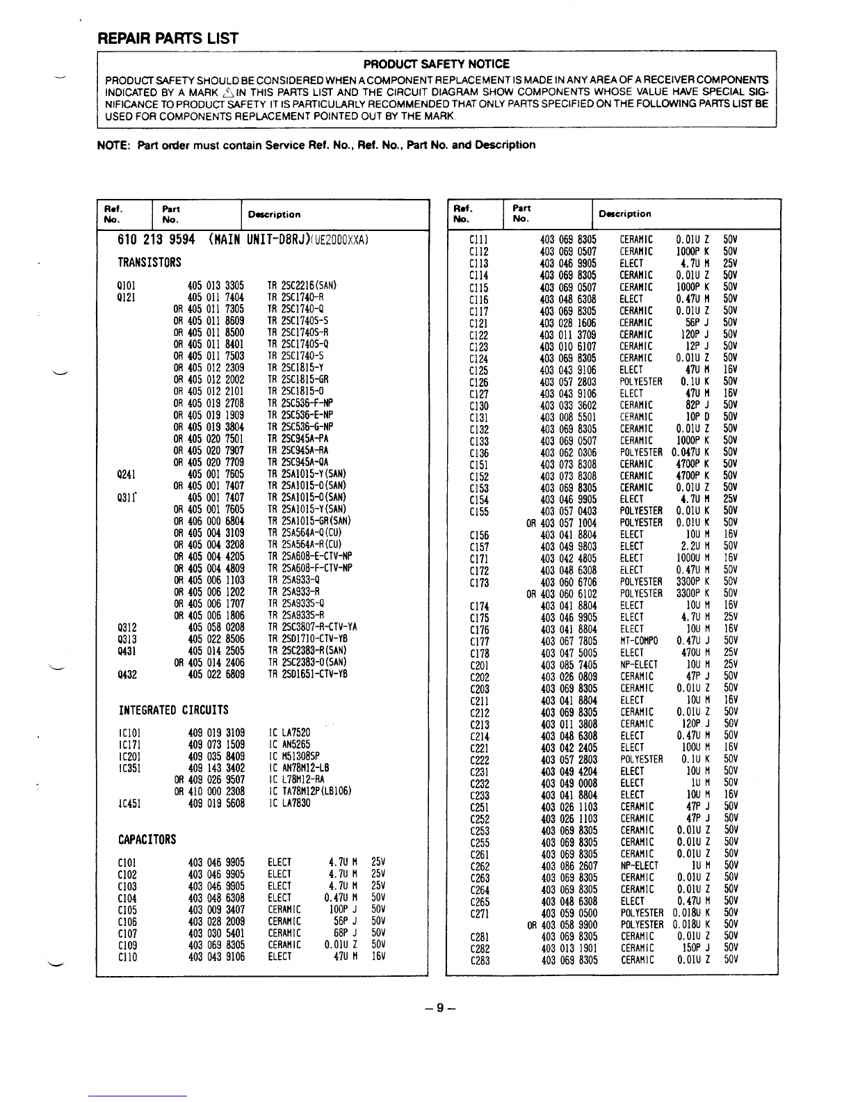
REPAIR PARTS LIST
PRODUCT SAFETY NOTICE
PRODUCT SAFETY SHOULD BE CONSIDERED WHEN A COMPONENT REPLACEMENT 1SMADE INANY AREA OF A REcEiVER COMPONENTS
INDICATED BY AMARK ~IN THIS PARTS LIST AND THE CIRCUIT DIAGRAM SHOW COMPONENTS WHOSE VALUE HAVE SPECIAL SIG-
NIFICANCE TO PRODUCT SAFETY IT IS PARTICUURLY RECOMMENDED THAT ONLY PARTS SPECIFIED ON THE FOLLOWING PARTS LISTBE
USED FOR COMPONENTS REPLACEMENT POINTED OUT BY THE MARK
NOTE: F%rtorder must contein Service Ref. No., Ref. No., pert No. and Description
Ref. Part
No. No. Description
610 2139594 (HAIN UNIT-D8RJ)fUE2000XXA)
TRANSISTORS
9101 4050133305 TR 2SC2216(SAN)
Q121 4050117404 TR 2SC1740-R
OR 405011 7305 TR 2SC1740-Q
OR 4050118609 TR 2SC1740S-S
OR 4050118500 TR 2SC1740S-R
OR 4050118401 TR 2SC1740S-Q
OR 4050117503 TR 2SC1740-S
OR 4050122309 TR 2SC1815-Y
OR 4050122002 TR 2SC1815-GR
OR 4050122101 TR 2SC1815-O
OR 4050192708 TR 2SC536-F-NP
OR 4050191909 TR 2SC536-E-NP
OR 4050193804 TR 2SC536-G-NP
OR 4050207501 TR 2SC945A-PA
OR 4050207907 TR 2SC945A-RA
OR 4050207709 TR 2SC945A-QA
Q241 4050017605 TR 2sAIo15-Y(SAN)
OR 405001 7407 TR 2SA1OI5-O(SAN)
Q31~ 4050017407 TR 2SA1015-O(SAN)
OR 4050017605 TR 2SAI015-Y(SAN)
OR 4060006804 TR 2SAIO15-GR(SAN)
OR 4050043109 TR 2SA564A-IJ(CU)
OR 4050043208 TR 2SA564A-R(CU)
OR 4050044205 TR 2SA608-E-CTV-NP
OR 4050044809 TR 2SA608-F-CTV-NP
OR 4050061103 TR 2SA933-Q
OR 4050061202 TR 2SA933-R
OR 4050061707 TR 2SA933S-Q
OR 4050061806 TR 2SA933S-R
9312 4050580208 TR 2sC3807-R-CTV-YA
Q313 4050228506 TR 2SO1710-CTV-YB
Q431 4050142505 TR 2SC2383-R(SAN)
OR 4050142406 TR 2sC2383-O(SAN)
Q432 4050226809 TR 2S01651-CTV-YB
INTEGRATEDCIRCUITS
Iclol 4090193109 IC LA7520
IC171 4090731509 lC AN5265
IC201 4090358409 IC H51308SP
IC351 4091433402 IC AN781f12-LE
OR 4090269507 IC L78tf12-RA
OR 4100002308 IC TA78H12P(LB106)
1C451 4090195608 lC LA7830
CAPACITORS
Clol 4030469905 ELECT 4.7U H 25v
CI02 4030469905 ELECT 4.7U H 25V
CI03 4030469905 ELECT 4.7U H 25V
C104 4030486308 ELECT o.47U H 50V
CI05 4030093407 CERAtflC IOOPJ 50V
C106 4030282009 CERAHIC 56P J 50v
CI07 4030305401 CERAMIC 68P J 50V
C109 4030698305 CERAMIC O.oluz 50V
Cllo 4030439106 ELECT 47U H 16v
Rof.Part
No. No. Description
Clll 4030698305 CERAMIC
C112 O.oluz 50V
4030690507 CERAMIC
CI13 1000PK 50V
4030469905 ELECT 4.7U H 25V
C114 4030698305 CERAHIC O.oluz 50V
CI15 4030690507 CERAHIC
c116
1000PK 50V
4030486308 ELECT o.47U H 50V
C117 4030698305 CERAH1C
C121
O.oluz 50V
4030281606 CERAHIC 56P J 50V
C122 4030113709 CERAHIC
C123
120PJ 50V
4030106107 CERAMIC 12P J 50V
C124 4030698305 CERAH[C O.olu z 50V
C125 4030439106 ELECT
C126
47U H 16v
4030572803 POLYESTER O.lU K 50V
C127 4030439106 ELECT
C130
47U H 16V
4030333602 CERAMIC 82P J 50V
C131 4030085501 CERAMIC
C132
IOP o 50V
4030698305 CERAHIC O.oluz 50V
C133 4030690507 CERAfl1C 1000PK 50V
C136 4030620306 POLYESTER O.047U K 50V
C151 4030738308 CERAHIC
C152
4700PK 50V
4030738308 CERAHIC 4700PK 50V
C153 4030698305 CERAHIC 040{ j :fi
C154 4030469905 ELECT
C155 4030570403 POLYESTER O.OIU K 50V
OR 4030571004 POLYESTER O.OIU K 50V
C156 4030418804 ELECT
C157
IOU H 16v
4030499803 ELECT
C171
2.2U M 50V
4030424805 ELECT 1000UH 16v
c172 4030486308 ELECT o.47U ti 50V
C173 4030606706 POLYESTER 3300PK 50V
OR 4030606102 POLYESTER 3300PK 50V
C174 4030418804 ELECT
C175
10U !! 16V
4030469905 ELECT 4.7U H 25V
C176 4030418804 ELECT
C177
IOU H 16V
4030677805 tlT-COHPO O.47U J 50V
c178 4030475005 ELECT 470U H 25V
C201 4030857405 NP-ELECT IOU H 25V
C202 4030260809 CERAMIC
C203
47P J 50V
4030698305 CERAHIC O.olu z 50V
C211 4030418804 ELECT 10U H 16V
C212 4030698305 CERAMIC O.olu z 50V
C213 4030113808 CERAHIC 120PJ 50V
C214 4030486308 ELECT o.47U H 50V
C221 4030422405 ELECT
C222
IOOUH 16V
4030572803 POLYESTER
C231
O.IU K 50V
4030494204 ELECT 10U M 50V
C232 4030490008 ELECT
c233
lU M 50V
4030418804 ELECT
C251
10U H 16v
4030261103 CERAHIC
C252
47P J 50V
4030261103 CERAHIC
C253
47P J 50V
4030698305 CERAMIC O.oluz 50V
C255 4030698305 CERAHIC O.oluz 50V
C261 4030698305 CERAHIC
C262
O.olu z 50V
4030862607 NP-ELECT
C263 lU M 50V
4030698305 CERAHIC O.oluz 50V
C264 4030698305 CERAHIC O.oluz 50V
C265 4030486308 ELECT
C271
0.47U n 50V
4030590500 POLYESTER O.018u K 50V
OR 4030589900 POLYESTER O.018u K 50V
C281 4030698305 CERAH1C
C282
O.oluz 50V
4030131901 CERAHIC
C283
150PJ 50V
4030698305 CERAMIC O.oluz 50V
—9–


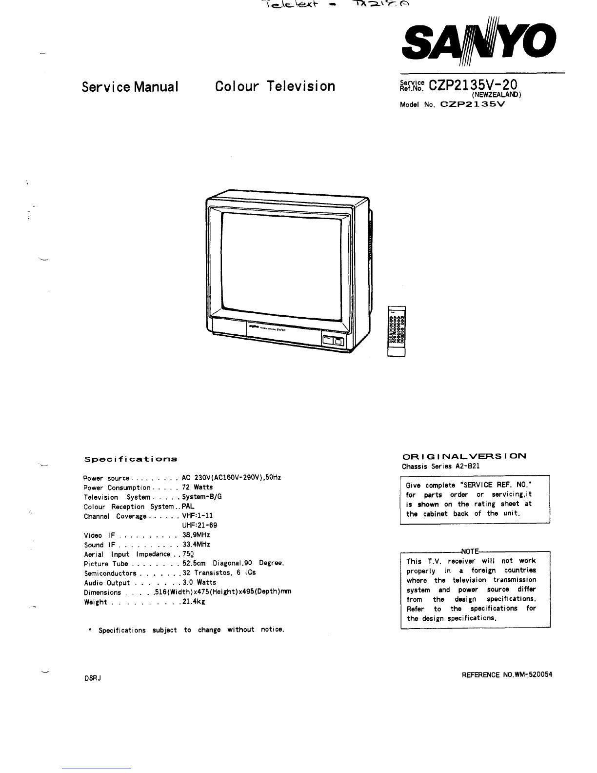
 User manual")


 User manual")