PROGRAMMING THE MULTIMEDIA REMOTE CONTROL
Find your code. It is next to the brand name
of your equipment in the chart below and
on page 8. (The illustrated example is for a
Sanyo VCR.)
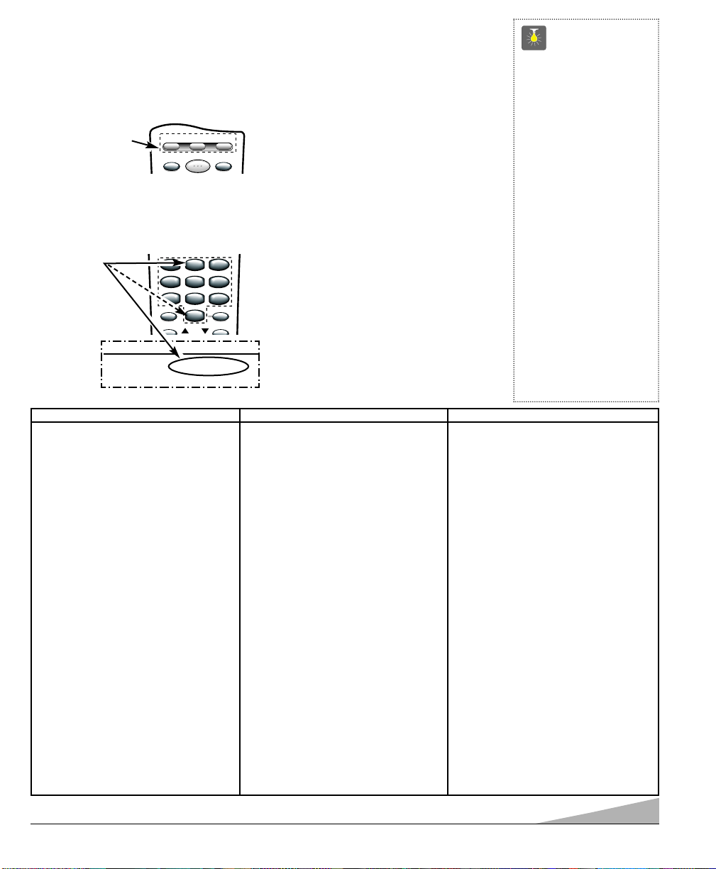
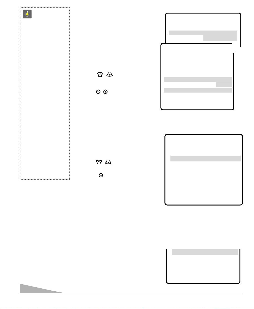
➊Press and hold VCR or AUX key.
❷Using the NUMBER keys on the
remote, enter the three-digit code
number for your VCR, DVD, or Cable
Box. The key will flash 5 times when
released if the code was accepted.
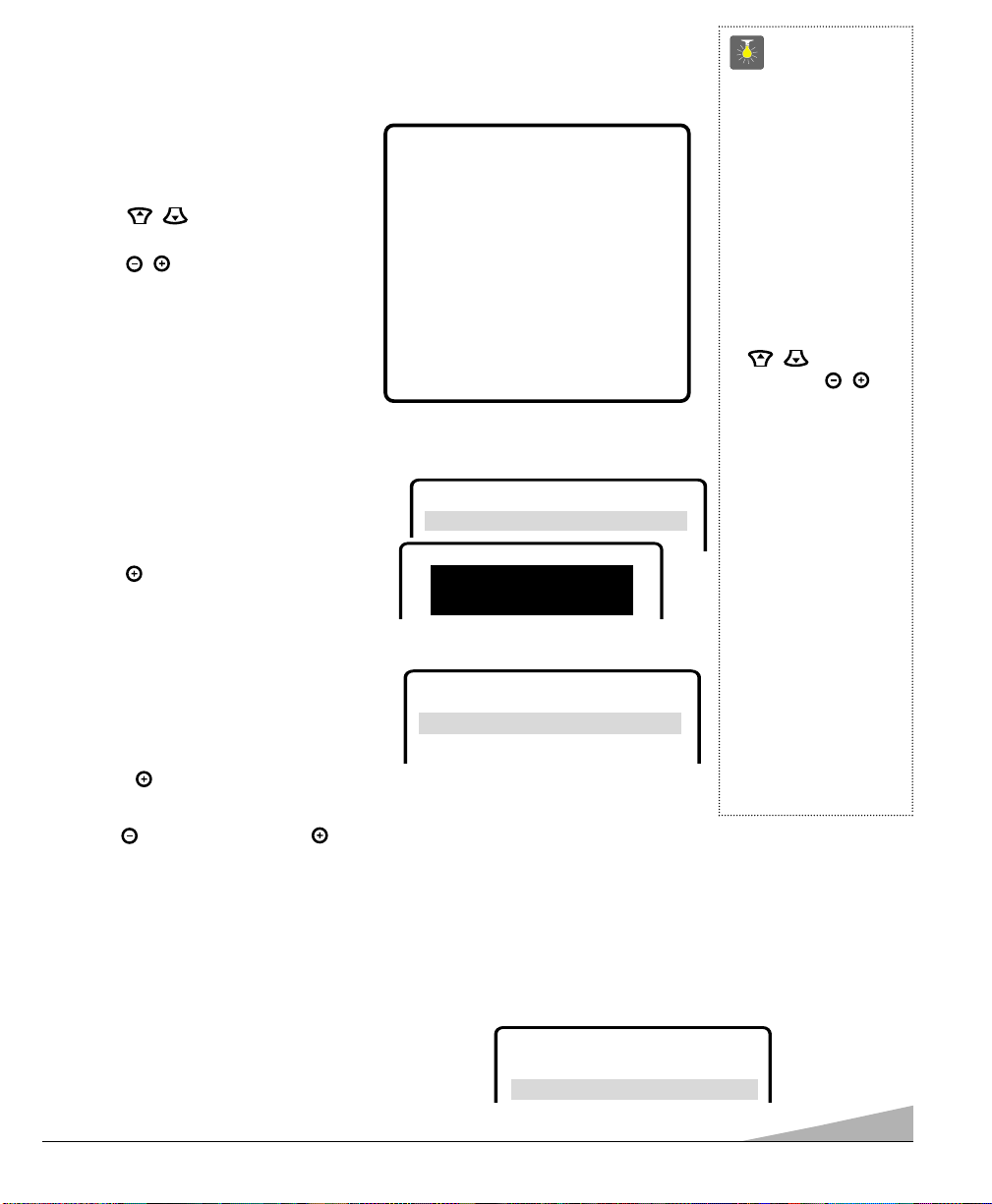
❸Press the POWER and CHANNEL keys
to check programming. If they operate
properly, programming is completed. If
not, use another code, if available and
repeat steps.
Notes:
–There may be VCRs, DVD’s, and cable
boxes that this remote control cannot
operate.
–Some manufacturers use different types
of remote controls. If your brand has
several codes listed, repeat steps ❶and
❷with each number until you find the
correct code. Write your codes in the
spaces on back of remote control and
page 8 for quick reference.
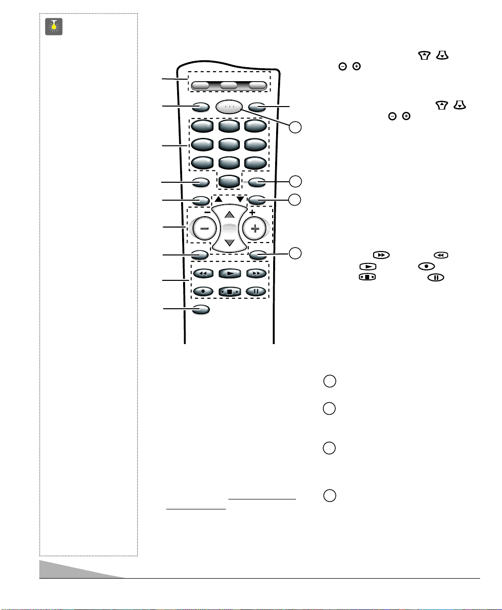
To Operate Your...
VCR—Press the VCR key.
Cable Box—Press the AUX key.
DVD Player—Press the AUX key.
Television—Press the TV key.
VCR ..............CODE
SANYO ..............200,201,202,203
SCOTT................
Enter Code:
Example: For a
Sanyo VCR, Enter
code “200”(from
chart below).
RECALLMENU
CAPTION SLEEP
CH
123
456
789
0
123
456
789
0
RESETINPUT POWER
VCR TV AUX
Press button
and hold down.
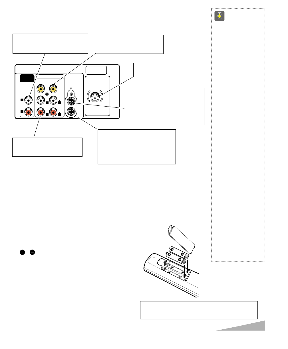
QuickTips
■
Make sure batteries
have been installed
correctly.
■
The remote control will
not operate my VCR,
DVD, or Cable Box.
– Press the VCR
or AUX key.
– Reprogram the
remote control.
■
Special key functions:
The INPUT key func-
tions as the VCR’s
TV/VCR key when the
Remote Control is in the
VCR mode.
■
The AUX mode will
accept codes for DVDs,
Cable boxes, or a VCR,
but only one at a time.
VCR Codes Chart
BRAND NAME CODE NO.
ADMIRAL ................... 234,239,243,247,224,229,222,215
ADVENTURA............... 228
AIKO............................ 240,205
AIWA .......................... 228,217
AKAI ........................... 209,215
AMERICA ACTION....... 205
AMERICA HIGH........... 232
BELL & HOWELL ....... 203
BROKSONIC ............... 234,243,247,227,204
CANDLE ..................... 233,240,222,223,204,205,208
................................... 211,216,217
CANON ....................... 232,216
CCE............................. 240,205
CINERAL..................... 240,205
CITIZEN ...................... 233,240,222,205,211,216,217
CRAIG ........................ 223,202,219
CRAVER...................... 204
CURTIS MATHES ....... 232,236,238,222,228,208,209
................................... 211,216,217
DAEWOO .................... 205,240,211
DAYTRON.................... 240,205
DENON........................ 221
DYNATECH ................. 228
EMEREX...................... 214
EMERSON .................. 234,236,240,243,247,223,227,228
................................... 203,204,205,206,210,211,217
FISHER ....................... 200,201,202,203,211
FUJI............................. 232
FUNAI ......................... 228,233,217
GARRARD................... 228
GE .............................. 222,246,232,236,239,226
................................... 229,224,208,212,216
GOLDSTAR ................ 223,238,226,206,208,215,217
GO VIDEO .................. 248,249,208,212,219
GRADIENTE................. 228
HARLEY DAVIDSON.... 228
HEADQUARTER........... 200
HITACHI ..................... 230,246,226,228,221,222,209,217
BRAND NAME......... CODE NO.
HUGHES...................... 221
JBL ............................. 237
JENSEN....................... 209
JVC ............................ 220,225,238,226,203,209,221
KEC............................. 240,205
KENWOOD ................. 226,238,220,201,203,209
KODAK........................ 232
LLOYD’S...................... 228
LOGIK ........................ 235,219
LXI ............................. 232,221,228,201,202,203,206
................................... 211,217
MAGNASONIC............. 223,240,205,219
MAGNAVOX ............... 204,232,228,211,216,217,219,220
MARTA........................ 206
MATSUSHITA ............. 232,216
MEI.............................. 232
MEMOREX ................. 232,239,243,245,223,224,228,
................................... 229,221,200,202,203,206,215
MINOLTA .................... 221
MITSUBISHI ............... 231,239,244,224,226,229,210,223
MOTOROLA................. 232,239,229,224
MTC ........................... 228,217,219
MULTITECH ............... 228,217
NEC ............................ 238,208,223,226,203,206,209
................................... 215,217
OLYMPUS................... 232
OPRIMUS.................... 239,245,248,223,224,229,203,208
ORION ........................ 243,227,234,205,206,210,211,240
PANASONIC ............... 245,232,236,223,202,211,216,219
PENNY ........................ 230,232,221,223,208,211,216,219
PENTAX ...................... 238,221
PHILCO ...................... 204,232,243,228,216,217
PHILIPS ..................... 204,232,211,216,217,228
PIONEER .................... 242,204,207,220
PROSCAN .................. 222,241,246,230,236,226
PROTON ..................... 219
PULSAR ..................... 233,240,205, 208,216,217
QUARTER.................... 200
BRAND NAME......... CODE NO.
QUARTZ...................... 200
QUASAR ..................... 245,232,236,223,216
RADIO SHACK ............ 228,245,223
RCA ............................ 221,241,246,230,232,236,239,224
................................... 226,229,221,201,207,208,210,216
REALISTIC ................. 232,239,223,224,228,229,200,201
................................... 202,203,206,208,216,217,245
SAMSUNG .................. 208,233,211,217,222
SANKY ........................ 239,229,224
SANSUI ...................... 243,226,228,209,219,220
SANYO ....................... 200,201,202,203
SCOTT ........................ 234,247,223,227,211
SEARS ........................ 232,223,228,221,200,201
,................................. 202,203,206,211,216,217
SEMP.......................... 211
SHARP ....................... 239,229,224
SHINTOM ................... 219,227
SIGNATURE ............... 217,239,229,224,200
SONY ......................... 214,218,232,237,226,228
STS............................. 221
SYLVANIA .................. 228,232,244,204,216,217
SYMPHONIC .............. 217,228,233,226,202
TATUNG ..................... 226,209
TEAC .......................... 228,209,214,217
TECHNICS................... 232
TEKNIKA .................... 232,223,228,216,217
TOMAS ....................... 228,217
TOSHIBA .................... 211,240,244,202,205,210
VECTOR ...................... 211
VIDEO CONCEPT......... 211
WARDS ...................... 230,232,239,223,224,228,229
................................... 221,202,204,208,211,217
WHITE
WESTINGHOUSE......... 240,243,205
XR-1000...................... 228,232
YAMAHA .................... 238,226
ZENITH ....................... 215,237,243,223,225,228,222
7