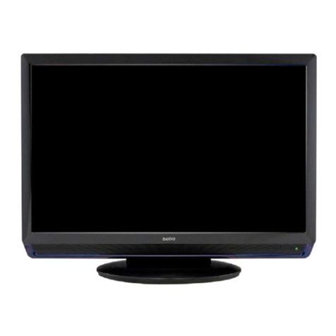
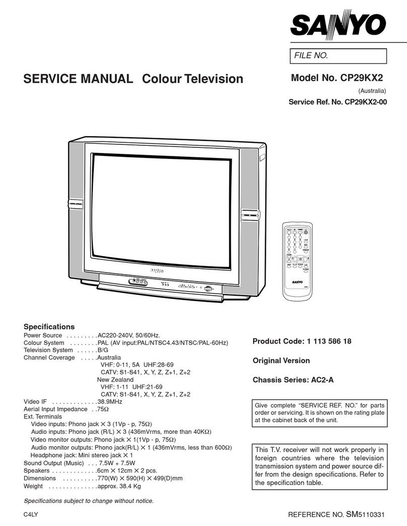
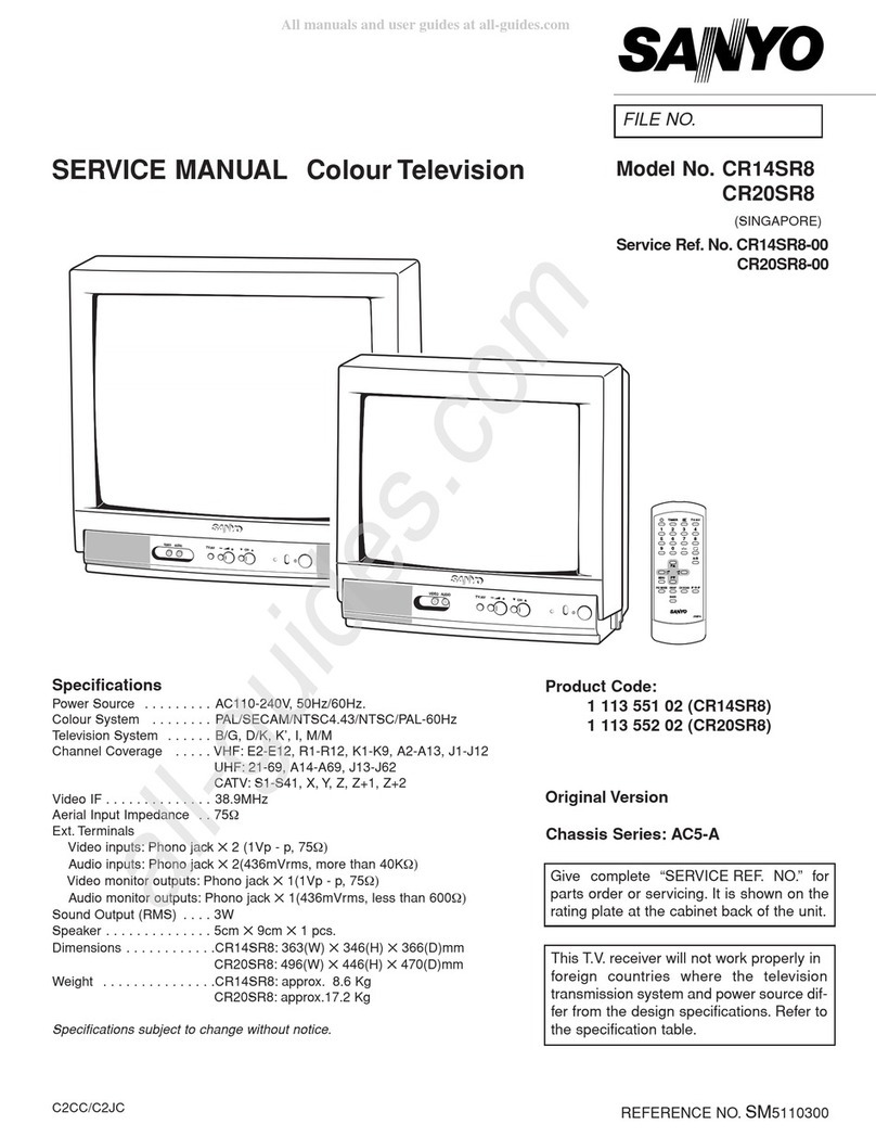
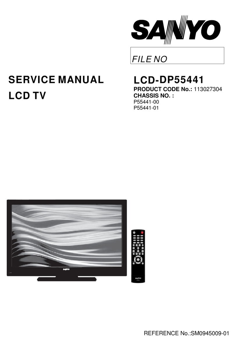
Sanyo CE27LC6BK-c User manual

Part No. SKSM0846 N2WLD/N2YLD MARCH 2006
Colour Television
Service Manual
Give complete "SERVICE REF. NO." for parts
order or servicing, it is shown on the rating sheet
on the cabinet back of the TV set.
Note
This TV receiver will not work properly in foreign
countries where the television transmission
system and power source differ from the design
specifications. Refer to the specifications for the
design specifications
CE27LC6BK-c
CE32LC6BK-c
Contents
Safety precautions/Specifications ..................................................................................................................2
Service Mode/Option settings ........................................................................................................................3
Block Diagram ................................................................................................................................................4
Power Diagram ..............................................................................................................................................5
IC Descriptions............................................................................................................................................6~7
IC Block Diagrams..........................................................................................................................................................................8~12
Cabinet Parts List ........................................................................................................................................13
Cabinet Disassembly....................................................................................................................................14
Pin description of semiconductors................................................................................................................15
Part Description and reading of schematic diagram ....................................................................................16
Electric Parts List....................................................................................................................................17~32
Please use Schematic Diagram SKP20572
inserted with this Service Manual.
Model CE27LC6BK-C
CE32LC6BK-C
Service Ref. No. CE27LC6BK-C-00
CE32LC6BK-C-00
PRODUCT CODE: 111376231 (27”)
111376332 (32”)
ORIGINAL VERSION:Chassis No.UK4-A

-2-
N2WLD/YLD
SAFETY PRECAUTION
PRODUCT SAFETY NOTICE
SPECIFICATIONS
Product safety should be considered when a component replacement is made in any area of a receiver. Components
indicated by mark in the parts list and the schematic diagram designate components in which safety can be of
special significance. It is particularly recommended that only parts designated on the parts list in this manual be used
for component replacement designated by mark . No deviations from resistance wattage or voltage ratings may be
made for replacement items designated by mark .
!
!
!
1: An isolation transformer should be connected in the
power line between the receiver and the AC line when a
service is performed on the primary of the converter
transformer of the set.
2: Comply with all caution and safety-related notes
provided on the cabinet back, inside the cabinet, on
the chassis or the picture tube.
3: When replacing a chassis in the cabinet, always be cer-
tain that all the protective devices are installed properly,
such as, control knobs, adjustment covers or shields,
barriers, isolation resistor-capacitor networks etc. Before
returning any television to the customer, the service tech-
nician must be sure that it is completely safe to operate
without danger of electrical shock.
Power source AC 220~240V, 50Hz
Television system System I, B/G, D/K, L.L’
Colour system PAL/NTSC4.43 (PAL/NTSC4.43/NTSC3.58 IN AV MODE)
Receiving channel UHF: #21~69
VHF: E2-E12, F2-F10, R1-R12
Aerial input impedance 75ohm
Rear AV terminal
AV1: CENELEC standard
INPUT: Composite video, RGB and Audio L/R
OUTPUT: TV-output with composite video and audio L/R
AV2: CENELEC standard
INPUT: Composite video, RGB, S-VHS and Audio L/R
OUTPUT: Monitor output with composite video and Audio L/R
AV3: CENELEC standard
INPUT: Composite video and Audio L/R
Side AV terminal
AV4: RCA Jacks
INPUT: Composite video and Audio L/R
AV terminal
AV5: INPUT: Component (Y,Pb,Pr)
HDMI INPUT: HDMI GROUP Standard
Headphone Socket Mini Jack
CE27LC6BK-C CE32LC6BK-C
Sound output(Continuous) 10W x 2 10W x 2
Contrast Ratio 900:1 1000:1
Display Resolution 1366 x 768 (WXGA) 1366 x 768 (WXGA)
Viewing Angles H: 176°, V: 176° H: 176°, V: 176°
Dimensions (WxHxD) 800 x 473.5 x 234 922 x 544 x 234mm
Weight 12.3 Kg 15.7 Kg
Important recycling information.
Your SANYO product is designed and
manufactured with high quality materials
and components which can be recycled
and reused.
This symbol means that electrical and
electronic equipment, at their end-of-life,
should be disposed of seprately.
In the European Union there are separate collection systems for
used electrical and electronic products.
Please help us to conserve the environment we live in!
Note: This symbol mark and recycle system are applied only to
EU countries and are not applied to other countries of the
world.
RoHS
.This product does not contain any hazardous substances prohibited by the RoHS Directive.
(You will find “R” or “Z” at the last digit of the serial number or an “RSF” label near the rating plate on
the RoHS compliant product.)
WARNING
.You are requested to use RoHS compliant parts for maintenance or repair.
.You are requested to use lead-free solder.
!
!
-3- N2WLD/YLD
To enter to the Service Mode
+ Press and hold the GREEN button on the remote control and then press the P▼button on the cabinet.
To select the service item and change data value
+ To select the adjustment item, use the P▲or P▼button.
+ To change the service data, use the Volume -(LEFT) or Volume + (RIGHT) button.
+ The data which is set in the service mode is stored into the memory IC automatically.
EXAMPLE: 000 UK4A 05.13
ITEM NO SECTION VALUE
ITEM
Exit from the Service Mode
+ Press the MENU button or turn off the TV set by using the Mains switch.
OPTION SETTINGS
UK4A ALIGNMENT MATRIX
OPTIONS CE27LC6-B CE27LD6-B CE27LC6BK-C CE27LD6BK-C CE32LC6-B CE32LD6-B CE32LC6BK-C CE32LD6BK-C
SERVICE ITEM 253 11111111
SERVICE ITEM 252 11111111
SERVICE ITEM 251 11111111
SERVICE ITEM 250 11111111
SERVICE ITEM 249 11001100
SERVICE ITEM 248 00000000
SERVICE ITEM 247 11111111
SERVICE ITEM 246 01010101
SERVICE ITEM 245 00000000
SERVICE ITEM 244 11111111
SERVICE ITEM 243 00000000
SERVICE ITEM 242 00000000
SERVICE ITEM 241 11111111
SHIPPING CONDITIONS PERSONAL DYNAMIC STANDARD ECHO
BRIGHTNESS 3 2 3 2 3 2 2 0
CONTRAST 4 0 5 0 4 0 3 1
COLOUR 3 2 3 2 3 2 2 0
SHARPNESS 3 2 3 2 3 2 1 6
PRESET
NOISEREDUCTION LOW LOW LOW LOW
DYN SKIN TONE ON ON ON ON
TEXT BRIGHTNESS MID MID MID MID
ATS
HDD
PATH HDD
COLORSYS
AFC
EU0 UK1IRE2UI3
PC
HD
DIG
BASS
SURROUND
WELTXT
P&P

-4-
N2WLD/YLD
BLOCK DIAGRAM
This is a diagram for all models and therefore differs slightly from the actual block diagram.
LCD PANEL
SCALER
Digital
Interface ADC
D-RGB
TEXT/OSD MIX
YC
IF
VIDEO SWITCH
RGB/YPBPR
MATRIX
VIFIN1 LOC2
PANEL
LVDS
VIF
TUNER
GTV
SCART1
SCART2
SCART3
CVBS1
TV OUT (CVBS)
RGB1
CVBS2
MON. OUT (CVBS)
RGB2
CVBS3
RGB
SWITCH
VIDEO
SWITCH
BA7652
SVO6/CVBS6
CVBS
CVBS_Y4
CVBS_Y5
SWO1_CVBS20_Y20
CVBS30_Y30
DVBO_IFVO_FMRO
CVBS4
SIDE AV
HDMI TMDS
BA7603
SiI9021
HDMI
DECODER D-RGB
RGB
CVBS
YUV SWITCH
BA7603
YUV
B2_PB21
G2_Y21
PV10_23
IN_R
IN_G
IN_B
R3_PR31
G3_Y31
B3_PB31
TUNER
DIGITAL TV MODULE
COMPONENT
YPBPR
RGB
SWITCH
BA7657
R2_PR21
N/C
N/C
Outline

-5- N2WLD/YLD
1
2
3
4
5
6
KQ
1
1
POWER 1
ON/OFF
IC6604 6V
POWER 4
PANEL ON
ON/OFF
IC6613
IC6600
IC6601
5V
3V3 STB
5V STB
24V
IC6610
IC6609
IC6608
IC6607
IC6606
IC6605
IC6603
IC6602
13V_PWR
9V
12V_FAN
5V_SW
3V3_SW
D5V
D3V3
1V8_SW
D1V8
POWER ARCHITECTURE
D6601
D6621
D6618
D6616
D6607
D6606
D6605
D6604
D6615
D6614
TO IC801
PIN E10
5V
1
2
3
4
5
KQ
24V
6V
D3V3
D5V
3V3_SW
5V_SW
12V_FAN
9V
PROTECT ARCHITECTURE
2
3
4
5
KR
POWER
TO
UNIT
POWER DIAGRAM FOR UK4A

-6-
N2WKD/YKD
IC Descriptions for UK4A
IC001
This is a LA4919N-E which is the audio amplifier for the set. It has left and right inputs from the LOC and left and
right outputs to the speakers and headphone socket. It also has mute and standby functions which are activated by
the LOC as appropriate.
IC1101 (monitor sets only)
This is a switching IC, NJM2233BM, which allows the sync signal input on monitor sets to be switched between pin
20 of SCART 1 (conventional & ALBOS) and pin 14 of SCART 1 (SIS signal). The IC takes a 5V supply and is
switched by the control line RGB_SW.
IC1205
This a ROHM BA7603F triple video switch which allows the RGB input to be switched between SCART 1 and
SCART 2. The switch is controlled by the RGB_SW line from the IC.
IC1222
This a MM1225XF which is an electronic switch. This IC selects either “scart2 monitor out” or “digital module cvbs”
as the output for scart 2. This is only active on digital sets.
IC1271
This a large multiway electronic switch, MM1631BJBE. Via the I2C lines the cpu can select any audio input L/R pair
and feed them to scart 3 or IC801.
IC151
BA2904F - this is an OP-AMP used to amplify the AGC voltage back to IC801.
IC1602
This is a “partial resonance power supply” IC. It is used as a SMP to supply the standby voltages.
IC1604 / IC671
This is a “precision shunt regulator” used in an “error amp” configuration to provide feedback control of the supply.
IC1801/1802
PCA9534PW - These are I2C expander IC’s. They convert I2C commands from IC801 into control lines.
IC1841/1851
These are OP-AMPS used to control the speed of the fans
IC4001
This is a SST SST39VF020 CMOS multi-purpose flash with a capacity of 2Mbits. It is connected to the LOC using
address lines, data input/output, write enable and control lines. The flash IC is powered by the 3V3 SW supply.
IC4002
This is a ROHM BD5260G open drain voltage detector IC which works in conjunction with the main power and the
3.3V standby line to control the back lights.
IC601
This is a “current mode PFC controller” operating in transition mode. It is used in conjunction with L603 as active
power phase correction.
IC6600
This is an LA5754 voltage regulator. It provides the 5v supply for the LCD panel.
IC6601
This is a BA33BC0FP voltage regulator. It converts the 5v standby supply to 3.3v.

-7- N2WLD/YLD
IC Descriptions for UK4A (continued)
IC6602
This is a BA09FP-E2 voltage regulator. It converts 13v to 9v.
IC6603
This is a BA12FP-E2 12v voltage regulator. It converts the main 13v supply down to 12v for the fan.
IC6604
This is a LA5754MP voltage regulator. This IC converts the main 13v supply down to 6v. IC801 can switch this IC on
and off via control line “Power 1”. Consequently all supplies developed from this 6v will also be switched (see power
architecture diagram on page 8)
IC6605 / 6 / 7 / 8 / 9 / 10
These are voltage regulators which convert the switched 6v supply down to 5v, 3.3v and 1.8v.
IC6613
This is a TC7SH02 2-INPUT NOR GATE. This IC controls the 5v power to the LCD panel. It is switched via control
lines “Power 4” and “Panel on”.
IC701
This is a THC63LVDM83R LVDS converter IC. This IC converts 3 sets of 8 bit data (R, G & B) into 4 channel and
clock data stream to the LCD panel.
IC8001
This is a HDMI receiver / convertor. HDMI data from K1006 is fed into this IC. The IC then extracts the video and
audio in digital format and sends the data to IC801. Audio data is converted to analogue via IC8501
IC801
This IC is the main control IC for the entire TV.
It incorporates:-
1) CPU for control and on-screen graphics presentation.
2) Video signal processor for controlling picture presentation and quality.
3) LCD scaler for converting different resolutions to the resolution of the LCD.
4) 100 page text decoder.
5) Stereo sound decoder.
6) Multi-system decoder (PAL, NTSC, SECAM etc.)
IC802
This is an 8K x 8 bit EEProm. It is used to store all the calibration data and user settings. When a new IC is fitted,
the CPU (IC801) will detect it and initialise the IC to the default factory settings.
IC8131
This is a 512 x 8 bit EEProm. It is used to store the resolutions that the tv is able to display along with the manufac-
turer, date of manufacture and model number. An external device (eg DVD) with HDMI will read this EEProm to
determine which resolution signal to send to the tv.
IC8141
This is an I2C isolation device
IC8501
This is a digital to analogue converter. It is used to convert the HDMI digital audio data to analogue.
IC8502
This is a dual OP-AMP and is used to bufffer the HDMI analogue signal to the audio selector IC (IC1271)

-8-
N2WKD/YKD
x
xxxxxxxx xxxxxxxxxxxxxxxxxxxxxxxxxxxxx xxxxxxxxxxxxxxxxxxxxxx xxxxxxxxxxx xxxxxxx xxxxxxxxxxxxxxxxxxx
xxxx xxxxxxxxxxxxxxxxxxxxxxxx xxxxxxx
Fig 1.Block diagram of LOC II
QSS SOUND IF
AG C
QSS MIXER
AM DEM O DULA TO R
VISION IF/AGC/AFC
PLL DEMOD.
VIDEO AMP.
SO UND TRAP
GR OUP DELAY
VIDEO SWITCH
VIDEO IDENT.
VIDEO FILTER S
PAL/SECAM/NTSC
H/V SYNC SEP.
H-OSC. + PL L
SIFIN/DVBIN
AG C O UT
VIFIN
CVBS 3/Y4
C5/C6
CVBS/30
C4/C30
CV BSO /PIP
SSIF
AUDIO CONTR OL
DV BO /FM RO
SW ITCH
CVBS 2/Y5
IFVO /SVO /
YSYN C
DVBO /IFVO/
QSSO /
SO UN D PLL
DEEM PH ASIS
CVBS/Y6
SVO /FMR O
BASE-BAND
FLASH
OS D
LINE
ME M O RY
OVER LAY
MIXER
AM O UT
DE LAY LINE
DE CO DE R
Y /CVBS /RG B /YPRPB
SW ITCH
CVBS20 / Y20
INSW 2 /C20
R2 /PR/C21
G /YIN2 /
B /P
BIN2
CV BS /YO U T
INSSW 3
R /P
RIN3 /C31
B /PBIN3
G /YIN3 /
CVBS / Y21
CVBS / Y31
H/Vsync
Y/CVBS
C/CV BS
U
V
AN TI
ALIAS
FILTER S
AUDIO DSP
DA Cs
AU D IO SELECT
ADCs / DACs
AD C s
TBC
AG C
2D/3D
CO M B
FILTER
RDS
CV BS/Y
U
V
DE INTER-
LACER
NO ISE
REDU CT .
BLAC K STRETC H
WHITE STRETCH
HO RIZ. SCALER
PEAKING / LTI / CTI
COLOR FEATURES
YU V
TO
RG B
MA TRIX
AD C
STER EO SOUND
DECO DE R
AUDIO IN/OUT
LINE O/I
C, S
C, SW I2SHP -OUT LS-OU T
MEM O RY
INTER FAC E
CN TRL
ADDR
DA TA
612 16
16 MBit
SD RAM
8051
MICRO -
CO NTR.
TXT
DE CO DE R
OS D
OS D
BLEN DER
I/Os
24
RG B/YUV
alpha
OU TPUT
FORM AT
RG B
DA Cs
RG B/
ITU
H, V,
CLK,
ClkRef
4 30/10
RO GO BO
AM
DIG ITAL
VIDEO
OU T
PAR.
VIDEO
INTER-
FACE
IN_R
IN_G
IN_B
SOGIN
RB IAS
AH S
AVS
AC LK
ASC L
ASD A
I
2C
HIF
LPLL TEST
IMA G E
GE N.
INPUT SELEC T
RG B 24 RG B 24
YU V 24RG B 24
YU V 24
AU TO
AD JUST
CO LOR
MA TRIX
HO RIZ. /VERT.
UP /DOWN
SC ALER
OU TPUT
CO LOR
LOOK -UP
TABLE
DITHER
UNIT
OU TPU T
INTER FACE
LVDS AND
TTL
RS P[13:0]
RS N[13:0]
RGB 18/
RG B24
RG B30
RG B24
YU V24
CRYST AL
OS CILLATO R
PANEL
PLL
FLASH
INTERFACE
GLOB AL
CO NTRO L
UNIT
O N-CHIP
MICRO CO NTRO LLER
80C51
TIME R
CO UNT ER
UART
I
2C
RXC TXDSC L SDA
GP IO
PW M
GP IO[23:16]
GP IO[15:0]
PW M[2:0]
INT_N
PO R_N
RS T_N
CFG [15:0]
FONT AND
CHA RA CT ER
RA M
T[1:0]
SR AM
IC801
IC BLOCK DIAGRAMS

-9- N2WLD/YLD
IC BLOCK DIAGRAMS
IC001 LA4919N-E <Audio Output>
HP IN1
HP IN2
HP D.C
HP Standby
AMP Standby
D.C
DDL
ON TIME
IN2
PRE GND
PRE VCC
IN-VREF
IN1
POWER GND
HP OUT1
HP OUT2
POWER GND
OUT2-
OUT2+
SW GND
SW B
SW E
SW OUT
13
14
13
12
11
10
9
8
7
6
5
4
3
2
128
27
26
25
24
23
22
21
20
19
18
17
16
15
Vcc
Voltage
Regulator
VG=6dB
VG=6dB
Ripple filter
H/P Standby SW
AMP Standby SW
Ripple filter
Muting circuit
used at power on
Non linear
amplifier
A
B
Output
amplifier
Output
amplifier
VCC
OUT1+
OUT1-
Non linear
amplifier
C
D
Output
amplifier
Output
amplifier
Output amplifier Stage
REF
amplifier
Input
amplifier
Switching
Drive
Power TR Stage
Head Phones Stage
Input amplifier Stage
Switching Regulator Stage
H. L. S
*H. L. S
Higher
Level signal
Selector
Switching Regulator BLOCK
ABCD
Input
amplifier
HEADPHONES BLOCK
IC1205 BA7603F

-10-
N2WKD/YKD
IC BLOCK DIAGRAMS
IC1271 (MM1631)
L1
L2
L3
L4
L5
L6
L7
L8
L9
L10
L11
R1
R2
R3
R4
R5
R6
R7
R8
R9
R10
R11
BIAS
SCL
SDA
ADR
MUTE
GND
LOUT10dB
VCC
ROUT10dB
LOUT20dB
ROUT20dB
LOUT30dB
ROUT30dB
BIAS Logic
33
35
1
3
5
7
9
11
13
15
17
34
36
2
4
6
8
10
12
14
16
18
19
23 22 21 20 24
30
29
28
27
26
25
31 32
Y-Decoder
I/O Buffers and Data Latches
1150 B1.1
Address Buffers & Latches
X-Decoder
DQ7-DQ0
Memory Address
OE#
CE#
WE#
SuperFlash
Memory
Control Logic
Functional Block Diagram
IC4001 (ST39VF0200)

-11- N2WLD/YLD
IC BLOCK DIAGRAMS
IC6600 / IC6604 (LA5754MP-DL-E)
IC601 L6562D
+
-
MULTIPLIER AND
VREF2
OVERVOLTAGE
DETECTION
VOLTAGE
REGULATOR
UVLO
INTERNAL
SUPPLY 7V
+
-
2.5V
R1
R2
R
S
Q
+
-
DRIVER
STARTER
+
-
ZERO CURRENT
DISABLE
2.1 V
1.6 V
Vcc
8
1
23 4
ZCD
Vcc
INV
COMP MULT CS
GD
7
5
GND
6
25 V
40K
5pF
15 V
Starter
stop
DETECTOR
THD OPTIMIZER

-12-
N2WKD/YKD
IC BLOCK DIAGRAMS
IC603 L6598D
GND
V
REF
Ifmin
Rfmin
VCO
EN1
Vthe1
Vthe2
EN2
V
S
V
BOOT
OUT
C
BOOT
LOAD
H.V.
LVG
UV
DETECTION
Vs
HVG
BOOTSTRAP
DRIVER HVG
DRIVER
LVG DRIVER
Css
V
REF
Ifstart
Rfstart
Cf
OP AMP +
-
OPOUT
OPIN-
OPIN+
DEAD
TIME DRIVING
LOGIC
CONTROL
LOGIC
Iss
+
-
+
-
LEVEL
SHIFTER
12
5
6
7
4
2
3
1
9
8
10
11
14
15
16
IC1801 / IC1802 PCA9534PW
POWER-ON
RESET
INPUT
FILTER I2C/SMBUS
CONTROL
INPUT/
OUTPUT
PORTS
WRITE pulse
READ pulse
A0
A1
A2
SCL
SDA
VDD
Vss
8-BIT
I/O0
I/O1
I/O2
I/O3
I/O4
I/O5
I/O6
I/O7
SU01783
NOTE: ALL I/Os ARE SET TO INPUTS AT RESET
Vcc
INT
LP
FILTER
PCA9534

-13- N2WLD/YLD
CABINET PARTS LIST FOR MODELS CE27/32LC6BK-C-00
CE27LC6BK-C-00
CABINET PARTS
1 665 000 4474 CABINET FRONT-N2WJA
2 610 319 4547 BUTTON UNITED-N2W
3 610 327 9800 CABINET BACK-N2WKD-A
4 610 319 4622 DOOR-N2WJ
5 665 000 6331 DEC SHEET BTM - N2WKB
6 610 319 6572 MOUNTING BRKT-N2WJ
7 610 326 7265 STAND FRAME-N2WKB
8 665 000 6355 STAND BASE-N2WKD
9 610 319 4806 TERMINAL BASE-N2WJ
10 645 076 4936 BADGE,SANYO*53.5X12L53.5
11 645 079 9488 PAD (BLACK) RICHCO RBS-24
12 610 325 7280 CHASSIS BASE-N2WJD
13 610 319 4639 DEC IND-N2WJ
14 610 315 1359 GASKET C-N2HE 80X13X13
15 610 320 2815 HOLDER FAN-N2WJ
Note: Parts order must contain Service Ref. No., Part No., and descriptions.
1/17 213
10
ACCESSORIES
16 645 079 4407 ASSY,REMOCON JXPTA
665 000 5990 BATT ENERGIZER R03SHP2VP
665 000 6362 27"/32"LCD CABLE INST SHT
665 000 6348 INST MANUAL-27"/32"WALLMT
665 000 5419 INST MANUAL-N2WLD/YLD(1)
665 000 5426 INST MANUAL-N2WLD/YLD(2)
665 000 5433 INST MANUAL-N2WLD/YLD(3)
CE32LC6BK-C-00
CABINET DIFFERENCES ONLY
17 665 000 4467 CABINET FRONT-N2YJA
18 610 327 9718 CABINET BACK-N2YKD-B
19 610 328 0837 CHASSIS BASE-N2YJD
20 610 314 7130 GASKET A-N2HE
7
4
8
15
6
12/19
9
Item Part No. Description Item Part No. Description
3/18
11(X 4)
DS
16

N2WKD/YKD -14-
CABINET DISASSEMBLY
CABINET BACK DISASSEMBLY
1. Remove 11 screws(A) for 27”/32”
2. Pull out the cabinet back.
(A) (A) (A)
(A)
(A)
(A) (A) (A) (A)
(A)
(A)

-15- N2WLD/YLD
N2WLD/YLD
PIN DESCRIPTION OF SEMICONDUCTORS
A
K
C
BE
C2
C1
B1 B2
E
C
CBE
KA
C
B
E
B2
B1
C1 C2
E
E
B
C
B2
B1
C1 C2
E
B2
B1 C1
C2
E1
E2
K
AA
A
KK
K
A
K
A
C
BECBEC
B
E
1
2
3
4
5
6
Index
12N
Index Index
12N
2
13
(IN) (OUT)
(GND)
21 4
2
1
3
Index
1
N
Index 1
N
Index 1
N
Index 1
N
Index 1
N
Index
1N
2
131
232
1
3
RESET GND
Vdd
5
3
D
GSD
G
S
K: Cathode
A: Anode
C: Collector
B: Base
E: Emitter
D: Drain
G: Gate
S: Source
●Diode
●Transistor/FET
●IC
E1
C2
E2 C1
B2
B1
Index
●Diode
●Transistor/FET
●IC
FET

-16-
N2WLD/YLD
PARTS DESCRIPTION AND READING IN SCHEMATIC DIAGRAM
1. The parts specification of resistors, capacitors and
coils are expressed in designated code. Please
check the parts description by the following code
table.
2. Some of transistors and diodes are indicated in
mark for the substitution of parts name. Please
check the parts name by the following code table.
3. Voltages and waveforms were taken with a video
colour bar signal(1Vp-p at 75 ohms terminated) and
controls to normal.
4. Voltages were taken with a high-impedance digital
voltmetre.
Example 2000 K K 1000 BG
Characteristic
Example 160 E M 10
Capacitance value
Tolerance
Type
Rated voltage
Excepting electric capacitors, all
capacitance values of less than 1
are expressed in µF and more
than 1 are in pF.
Example L2 C1 4R7 K N
Tolerance
Inductance value
Manufacture code
Unique code
Mark Material
E Electrolytic
P Electrolytic (non-Polarised)
C Ceramic (temperature compensation)
K Ceramic
F Polyester
N Polypropylene
M Metalised polypropylene
H Metalised polypromylar
B Ceramic (semiconductor)
G Metalised polyester
Y Composite film
S Styrol
T Tantalum oxide solid electrolytic
U Organic semiconductive electrolyte
D Electric double layer electrolytic
Mark Tolerance
A not specified
B ±0.1
C ±0.25
D ±0.5
F±1
G±2
E ±2.5
H±3
J±5
K±0
M±20
N±30
P +100 -0
Q +30 -10
T +50 -10
U +75 -10
V +20 -10
W +100 -10
X +40 -20
Y +150 -10
Z +80 -20
Mark Tolerance (nH) Mark Tolerance (%)
C ±0.25 G ±2
D ±0.5 J ±5
S ±0.3 K ±10
A ±0.2 L ±15
M±20
Coil Reading
Capacitor Reading
Example 1/2 D J 10K B
Example 6 W K 8.2
Example 1/2 C K 1M
Resistor Reading
Characteristic
Z (Carbon fuse)
B (Non-burnable)
Resistance value
Tolerance (see below table)
Material (see below table)
Rated wattage (W)
K indicates in KΩ
M indicate in MΩ
Note: Resistor which is indicated with resistance value only are
1/6W carbon resistor. Resistor which is indicated with materi-
al, tolerance and value are 1/4W rated wattage.
Mark Material
D Carbon
N Metal film
S Oxide metal film
C Solid
G Metal glaze
W Wire wounding or cement
H Ceramic
F Fusible
Mark Tolerance
A ±0.05
B ±0.1
C ±0.25
D ±0.5
F±1
G±2
J±5
K±10
M±20
P +5 -15
Z used in 0 ohm
●Material table ●Tolerance table
Mark Type number
-- 1S1555,1S2473,1S2076,1SS133,DS442,1SS176
K 1S1555,1S2473,1S2076,DS442
L 1S1555,1S2076A,1S2471
M 1SS133,1SS176,GMA01
N 1S1555,1S2473,1S2076,1SS133,DS442,1SS176,1N4148
P 1S1555,1S2076A,1S2471,1N4148
R 1S1555,1S2076,1S2473,DS442,1N4148
AA 1S1555,1S2076,1S2473,1SS133,DS442,1SS176,1N4148,GMA01
●Diode
Mark Type number
-- 2SC536 2SC945A 2SC1815 2SC1740 2SC1740S KSC945C
A E, F, G P, Q, R O, Y, G Q, R, S Q, R, S
B E, F, G P, Q, R O, Y, G Q, R, S
D F, G P, Q Y, G Q, R, S
F F, G P G R, S
H F, G P, Q Y, G Q, R, S Y, G
I E, F, G P, Q, R O, Y, G Q, R, S Y, G
G F, G P G R, S G
AD F, G Q, R Y, GR Q, R, S
AE E, F, G Q, R O, Y, GR Q, R, S
●Transistor (NPN type)
Mark Type number
-- 2SA608 2SA564A 2SA1015 2SA933 2SA933S KSA733C
Y E, F Q, R O, Y, G Q, R
WF R Y,GR
V E, F Q, R O, Y, G Q, R Y, G
U F R Y, G R G
Z E, F Q, R O, Y, G Q, R Q, R
AB F R Y Q, R
AE E, F Q, R O, Y R
●Transistor (PNP type)
Diode/Transistor Type Reading

N2WLD/YLD
-17-
CHASSIS ELECTRICAL PARTS LIST
Product safety should be considered when a component replacement is made in any area of a receiver.
Components indicated by a mark in this parts list and the circuit diagram show components whose value have
special significance to product safety. It is particularly recommended that only parts specified on the following
parts list be used for components replacement pointed out by the mark .
!
!
013N2WLD ELECTRICAL PARTS
LIQUID CRYSTAL DISPLAY
EL901 645 082 1707 LCD(V270B1-L01 REVC1)
ELECTRICAL
FN901 645 068 3763 MOTOR,FAN DC
KLP-PN 610 329 2243 CORD,30P 1.25MM(LVDS)
SP901 652 001 4473 SPEAKER,8
SP902 652 001 4473 SPEAKER,8
W900 645 012 7632 EURO PLUG +2P HOUSE @ 2.1
W900-1 645 020 3640 FERRITE RING
013N2YLD ELECTRICAL PARTS
LIQUID CRYSTAL DISPLAY
EL901 645 082 1714 LCD(V320B1-L01 REVC4)
ELECTRICAL
FN901 645 068 3763 MOTOR,FAN DC
KLP-PN 610 328 6594 CORD 30P 1.25MM(LVDS)
SP901 652 001 4473 SPEAKER,8
SP902 652 001 4473 SPEAKER,8
W900 645 012 7632 EURO PLUG +2P HOUSE @ 2.1
W900-1 645 020 3640 FERRITE RING
1AA0B10N1970A ASSY,PWB,CONTROL,N3KM
CAPACITOR
C3901 403 184 7910 ELECT 22U M 6.3V
C3902 403 149 9218 GRM188F51H103ZA01D PT115
C3903 403 164 0214 GRM188F51E104ZA01D PT115
C3904 403 113 3815 GRM188R71H102KA01D PT115
DIODE
D3901 408 039 4400 SLZ-981B-09H-AB-T1 LED
D3951 407 206 5618 ZENER D. UDZS-TE-1710B
D3952 407 206 5618 ZENER D. UDZS-TE-1710B
RESISTOR
R3901 401 255 6510 MT-GLAZE 100 JA 1/10W
R3902 401 255 6510 MT-GLAZE 100 JA 1/10W
R3905 401 256 7516 MT-GLAZE 390 JA 1/10W
R3951 401 255 6510 MT-GLAZE 100 JA 1/10W
R3952 401 150 6219 MT-GLAZE 1K JA 1/10W
R3953 401 162 4012 MT-GLAZE 560 JA 1/10W
R3954 401 256 7516 MT-GLAZE 390 JA 1/10W
R3955 401 256 6212 MT-GLAZE 270 JA 1/10W
!
!
Ref. No. Part No. Description
Chassis construction
CE27LC6BK-C-00
013N2WLD ELECTRICAL PARTS (PAGE 17)
1AA0B10N1970A ASSY,PWB,CONTROL,N3KM (PAGE 17 - 18)
1AA0B10N19200 ASSY,PWB,POWER,N2WKD (PAGE 18 - 20)
1AA0B10N176C0 ASSY,PWB,MAIN,N2WLD (PAGE 20 - 29)
CE32LC6BK-C-00
013N2YLD ELECTRICAL PARTS (PAGE 17)
1AA0B10N1970A ASSY,PWB,CONTROL,N3KM (PAGE 17 - 18)
1AA0B10N19200 ASSY,PWB,POWER,N2WKD (PAGE 18 - 20)
1AA0B10N176C0 ASSY,PWB,MAIN,N2WLD (PAGE 20 - 29)
Read description in the Capacitor and Resistor as follows:
CAPACITOR
CERAMIC 100P K 50V
Tolerance Symbols:
Less than 10PF
A: Not specified B: ±0.1PF C: ±0.25PF
D: ±0.5PF F: ±1PF G:±2PF
R: ±0.25-0PF S: ±0-0.25PF E: +0-1PF
More than 10PF
A: Not specified B: ±0.1% C: ±0.25%
D: ±0.5% F: ±1% G:±2%
H: ±3% J: ±5% K: ±10%
L: ±15% M: ±20% N: ±30%
P: +100-0% Q: +30-10% T: +50-10%
U: +75-10% V: +20-10% W:+100-10%
X: +40-20% Y: +150-10% Z: +80-20%
Material:
CERAMIC............Ceramic
MT-PAPER ..........Metallized Paper
POLYESTER ......Polyester
MT-POLYEST......Metallized Polyester
POLYPRO............Polypropylene
MT-POLYPRO ....Metallized Polypropylene
COMPO FILM......Composite film
MT-COMPO ........Metallized Composite
STYRENE............Styrene
TA-SOLID ............Tantalum Solid
AL-SOLID............Aluminium Solid
ELECT ................Electrolytic
NP-ELECT ..........Non-polarised Electrolytic
OS-SOLID ..........Aluminium Solid with Organic Semiconductive Electrolytic
DL-ELECT ..........Double Layered Electrolytic
RESISTOR
CARBON 4.7K J A 1/4W Rated Wattage
Performance Symbols:
A: General B: Non flammable Z: Low noise
Other: Temperature coefficient
Tolerance Symbols:
A: ±0.05% B: ±0.1% C:±0.25% D: ±0.5%
F: ±1% G: ±2% J: ±5% K: ±10%
M:±20% P: +5-15%
Rated value, ohms:
K: 1,000, M: 1,000,000
Material:
CARBON ............Carbon
MT-FILM ..............Metal Film
OXIDE-MT ..........Oxide Metal Film
SOLID..................Composition
MT-GLAZE ..........Metal Glaze
WIRE WOUND ....Wire Wound
CERAMIC RES....Ceramic
FUSIBLE RES ....Fusible
Rated Voltage
Rated value: P=pico farad, U=Micro farad
Note: Parts order must contain Service Ref. No., Part No., and descriptions.

-18-
N2WLD/YLD
Ref. No.
Part No.
Ref. No. Part No.
Description Description
R3956 401 162 2919 MT-GLAZE 220 JA 1/10W
R3957 401 162 2216 MT-GLAZE 10 JA 1/10W
R3958 401 150 6011 MT-GLAZE 0.000 ZA 1/10W
R3959 401 150 6011 MT-GLAZE 0.000 ZA 1/10W
MISCELLANEOUS
A3901 645 075 9734 UNIT,REMOCON RECEIVER
K39J 645 074 0343 PLUG,SIDE-ZR-SM3 8P PBF
SC3903 645 076 3502 SURGE-ABSORBER
SC3904 645 076 3502 SURGE-ABSORBER
SW3951 645 026 2791 SWITCH,PUSH 1P-1TX1
SW3952 645 026 2791 SWITCH,PUSH 1P-1TX1
SW3953 645 026 2791 SWITCH,PUSH 1P-1TX1
SW3954 645 026 2791 SWITCH,PUSH 1P-1TX1
SW3955 645 026 2791 SWITCH,PUSH 1P-1TX1
Z3901 610 324 0985 SHIELD CASE RC-N3AJ
1AA0B10N19200 ASSY,PWB,POWER,N2WKD
CAPACITOR
C1621 403 224 5715 CERAMIC 1000P K 50V
C1622 403 155 2210 GRM188R71H332KA01D PT115
C1623 404 106 7602 ELECT 150U M 400V
C1624 403 157 3611 GRM1885C1H101JZ01D PT115
C1625 403 370 1517 CERAMIC 0.1U K 50V
C1626 403 148 1718 ELECT 100U M 35V
C1627 403 167 8613 DEHR33D221KP3A
C1630 403 222 1303 CERAMIC 1000P K 1K
C1631 403 334 4209 ELECT 2200U M 16V
C1634 403 222 1303 CERAMIC 1000P K 1K
C1635 403 334 4209 ELECT 2200U M 16V
C1636 403 358 3212 CERAMIC 10U K 6.3V
C1637 403 370 1517 CERAMIC 0.1U K 50V
C1638 403 283 6319 CERAMIC 1U Z 10V
C1639 403 224 6118 CERAMIC 0.01U K 50V
C1692 403 334 4209 ELECT 2200U M 16V
C1693 403 370 1517 CERAMIC 0.1U K 50V
C605 403 222 1303 CERAMIC 1000P K 1K
C608 404 094 2009 MT-POLYEST 0.47U K 275V
C609 404 108 3800 330P M 250V
C613 404 093 6107 MT-POLYEST 0.1U M 275V
C614 403 222 1303 CERAMIC 1000P K 1K
C616 403 222 1303 CERAMIC 1000P K 1K
C617 403 420 8708 ELECT 47U M 35V
C618 403 260 1620 MT-POLYEST 1U J 400V
C619 404 108 3800 330P M 250V
C620 403 167 8613 DEHR33D221KP3A
C621 403 224 6118 CERAMIC 0.01U K 50V
C623 403 372 7517 CERAMIC 2.2U K 6.3V
C624 403 260 1620 MT-POLYEST 1U J 400V
C625 403 135 0717 CERAMIC 1U K 25V
C626 403 370 1517 CERAMIC 0.1U K 50V
C627 403 224 6118 CERAMIC 0.01U K 50V
C628 403 135 0717 CERAMIC 1U K 25V
C629 404 094 2009 MT-POLYEST 0.47U K 275V
C631 403 370 1517 CERAMIC 0.1U K 50V
C637 404 073 5106 DE1B3KX471KB5BC05 250V
C638 404 073 4406 CERAMIC 220P K 250V
C639 403 370 1517 CERAMIC 0.1U K 50V
C640 403 367 6518 CERAMIC 0.056U K 50V
C641 403 222 1303 CERAMIC 1000P K 1K
C642 403 157 6414 GRM188R71H331KD01D PT115
C643 403 283 6319 CERAMIC 1U Z 10V
C644 404 093 6107 MT-POLYEST 0.1U M 275V
C645 403 420 8708 ELECT 47U M 35V
C646 403 383 5212 CERAMIC 4.7U K 6.3V
C647 404 106 7701 ELECT 150U M 400V
C649 404 073 5106 DE1B3KX471KB5BC05 250V
C650 404 073 3904 DE1B3KX102MB5BC05
C651 403 417 9919 CERAMIC 4.7U Z 25V
C652 403 256 2416 GRM21BF51H224ZA01L PT297
C658 403 245 4424 DEHR33D471KB3B
C659 403 440 5216 MT-POLYPRO 0.056U K 630V
C662 403 299 1612 CERAMIC 1U K 16V
C663 403 350 5016 ELECT 1000U M 25V
C664 403 358 7606 ELECT 470U M 35V
C665 403 427 5304 ELECT 100U M 25V
C666 403 370 1517 CERAMIC 0.1U K 50V
C668 403 358 7606 ELECT 470U M 35V
C671 403 350 5016 ELECT 1000U M 25V
C676 403 358 7606 ELECT 470U M 35V
C689 403 370 1517 CERAMIC 0.1U K 50V
C690 404 106 7602 ELECT 150U M 400V
C691 403 370 1517 CERAMIC 0.1U K 50V
C692 403 325 6314 CERAMIC 0.22U K 10V
DIODE
D1606 407 006 6310 DIODE ERC05-10B
D1607 407 190 4116 DIODE SFPL-52V
D1608 407 149 0817 DIODE 1SS355-TE-17
D1609 407 206 5618 ZENER D. UDZS-TE-1710B
D1610 407 206 5618 ZENER D. UDZS-TE-1710B
D1613 407 190 4116 DIODE SFPL-52V
D1615 407 146 8113 DIODE EG01C
D1616 407 206 5410 ZD UDZS-TE-178.2B
D1618 407 006 6310 DIODE ERC05-10B
D1621 407 231 7707 PHOTO COUPLE TLP421F
D1622 407 231 7707 PHOTO COUPLE TLP421F
D1623 407 252 6911 ZENER DIODE
D1624 407 252 6911 ZENER DIODE
D1625 407 252 6911 ZENER DIODE
D1628 407 251 9507 DIODE YG862C10R-MY
D1628A 610 326 1676 HEAT SINK N3LA-E
D1629 407 251 9507 DIODE YG862C10R-MY
D1629A 610 328 2626 HEAT SINK N3KA
D1630 407 149 0817 DIODE 1SS355-TE-17
D1632 407 149 0817 DIODE 1SS355-TE-17
D1633 407 149 0817 DIODE 1SS355-TE-17
D1634 408 060 3908 DIODE ST02D-170-4000
D1635 408 060 3908 DIODE ST02D-170-4000
D601 407 149 0817 DIODE 1SS355-TE-17
D603 408 059 0406 DIODE D10XB80-7101
D603A 610 326 1348 HEAT SINK N3LA-G
D604 407 231 7707 PHOTO COUPLE TLP421F
D605 407 231 7707 PHOTO COUPLE TLP421F
D606 407 231 7707 PHOTO COUPLE TLP421F
D610 407 149 0817 DIODE 1SS355-TE-17
D611 407 207 6614 ZENER DIODE PTZ-TE2520B
D615 407 249 4309 DIODE FMD-G26S
D616 407 190 4116 DIODE SFPL-52V
D624 407 251 9606 DIODE YG865C10R-MY
D624A 610 326 1645 HEAT SINK N3LA-F
D627 407 251 9606 DIODE YG865C10R-MY
D639 407 221 9615 ZENER DIODE UDZS27B-TE-17
D640 407 149 0817 DIODE 1SS355-TE-17
D641 407 218 7617 ZENER DIODE UDZS18B-TE-17
D642 407 190 4116 DIODE SFPL-52V
D643 407 149 0817 DIODE 1SS355-TE-17
D644 407 149 0817 DIODE 1SS355-TE-17
D645 407 149 0817 DIODE 1SS355-TE-17
D646 407 179 1211 ZENER DIODE PTZ13B-TE25
D647 407 149 0817 DIODE 1SS355-TE-17
D670 407 149 0817 DIODE 1SS355-TE-17
D691 407 149 0817 DIODE 1SS355-TE-17
D692 407 149 0817 DIODE 1SS355-TE-17
D693 407 149 0817 DIODE 1SS355-TE-17
INTEGRATED CIRCUIT
IC1602 409 653 7402 IC MR4010-7101
IC1602A 610 325 7242 HEAT SINK N3LA-D
!
!
!
!
!
!
!
!
!
!
!
!
!
!
!
!
!

-19- N2WLD/YLD
Ref. No. Part No. Description Ref. No. Part No. Description
IC1604 409 180 2307 IC UPC1093J
IC601 409 666 5313 IC L6562D
IC603 409 666 5214 IC L6598D
IC671 409 180 2307 IC UPC1093J
COIL
LF641 645 068 2902 LINE FILTER TOUHOUAEN
LF642 645 068 2902 LINE FILTER TOUHOUAEN
L1624 652 000 1817 PIPE CORE BF2030RTM TAPED
L601 645 076 7975 INDUCTOR,110U
L603 645 076 5643 INDUCTOR,200U
L613 645 047 6556 INDUCTOR,4.7U M
L614 645 047 6556 INDUCTOR,4.7U M
L617 652 001 0147 CORE,PIPE
L618 652 000 1817 PIPE CORE BF2030RTM TAPED
L619 652 001 0147 CORE,PIPE
L620 652 001 0147 CORE,PIPE
L621 652 000 1817 PIPE CORE BF2030RTM TAPED
TRANSISTOR
Q1610 405 167 6118 TR 2SD2226K-T146-V
Q1611 405 014 4519 TR BC847B,235 10000/REEL
Q1612 405 014 4519 TR BC847B,235 10000/REEL
Q602 405 167 6118 TR 2SD2226K-T146-V
Q603 405 014 4519 TR BC847B,235 10000/REEL
Q604 405 014 4519 TR BC847B,235 10000/REEL
Q605 405 134 5925 TR BC857B,235 10000/REEL
Q606 405 014 4519 TR BC847B,235 10000/REEL
Q607 405 213 5000 TR STP20NM50FP-SA1
Q607A 610 325 7082 HEAT SINK N3LA-C
Q608 405 014 4519 TR BC847B,235 10000/REEL
Q609 405 014 4519 TR BC847B,235 10000/REEL
Q610 405 134 5925 TR BC857B,235 10000/REEL
Q641 405 216 3409 TR 2SK3505-01MR-MY
Q641A 610 328 2565 HEAT SINK N3KA-A
Q642 405 216 3409 TR 2SK3505-01MR-MY
Q670 405 167 6118 TR 2SD2226K-T146-V
Q691 405 134 5925 TR BC857B,235 10000/REEL
Q693 405 014 4519 TR BC847B,235 10000/REEL
Q694 405 134 5925 TR BC857B,235 10000/REEL
RESISTOR
RL1603 645 030 5597 RELAY STD-S-105LMR
RL601 645 030 5597 RELAY STD-S-105LMR
RL670 645 086 0737 RELAY AJW2211F
R1610 401 062 1200 OXIDE-MT 470 JA 1W
R1611 401 105 0316 MT-GLAZE 10 JA 1/16W
R1612 401 105 2914 MT-GLAZE 22K JA 1/16W
R1613 401 105 0613 MT-GLAZE 10K JA 1/16W
R1614 401 111 6319 MT-GLAZE 470 JA 1/2W
R1615 401 105 5311 MT-GLAZE 4.7K JA 1/16W
R1616 401 105 2815 MT-GLAZE 2.2K JA 1/16W
R1617 401 212 1718 MT-GLAZE 24K FA 1/16W
R1618 401 226 1216 MT-GLAZE 150 FA 1/16W
R1619 401 212 1718 MT-GLAZE 24K FA 1/16W
R1620 401 105 4512 MT-GLAZE 390 JA 1/16W
R1621 401 264 7119 MT-GLAZE 24K FA 1/10W
R1622 401 012 4553 CARBON 100 JA 1/4W
R1624 401 105 2914 MT-GLAZE 22K JA 1/16W
R1625 401 105 0613 MT-GLAZE 10K JA 1/16W
R1627 401 035 5214 MT-GLAZE 10K JA 1/8W
R1628 401 105 7513 MT-GLAZE 82K JA 1/16W
R1629 401 105 3416 MT-GLAZE 27K JA 1/16W
R1633 401 162 6214 MT-GLAZE 68 JA 1/2W
R1634 401 064 1802 OXIDE-MT 0.39 JA 2W
R1635 401 037 0118 MT-GLAZE 5.6K JA 1/8W
R1636 401 037 3119 MT-GLAZE 7.5K JA 1/8W
R1637 401 037 3812 MT-GLAZE 8.2K JA 1/8W
R1638 402 104 8904 FUSE RES 470 J 1/2W
R1642 401 269 1508 OXIDE-MT 0.56 JA 2W
R1643 424 006 1302 FUSE 250V 2.5A
R1653 401 162 6214 MT-GLAZE 68 JA 1/2W
R1654 401 150 5915 MT-GLAZE 10K JA 1/10W
R1655 401 150 5915 MT-GLAZE 10K JA 1/10W
R1656 401 150 5915 MT-GLAZE 10K JA 1/10W
R1657 401 150 5915 MT-GLAZE 10K JA 1/10W
R1659 401 162 3619 MT-GLAZE 470 JA 1/10W
R1660TM 401 024 7440 CARBON 10K JA 1/6W
R602 401 105 7919 MT-GLAZE 0.000 ZA 1/16W
R603 401 105 7919 MT-GLAZE 0.000 ZA 1/16W
R604 401 007 2913 CARBON 1M JA 1/2W
R605 401 105 2914 MT-GLAZE 22K JA 1/16W
R606 401 105 0613 MT-GLAZE 10K JA 1/16W
R607 401 150 5915 MT-GLAZE 10K JA 1/10W
R608 401 105 0316 MT-GLAZE 10 JA 1/16W
R609 408 056 3707 THERMISTOR NTPAD5R1LGA0
R610 401 010 9213 CARBON 560K JA 1/2W
R611 401 105 0613 MT-GLAZE 10K JA 1/16W
R612 401 256 7714 MT-GLAZE 3.9M JA 1/10W
R613 401 102 7417 MT-GLAZE 10 JA 1W
R614 401 242 5311 MT-GLAZE 470K JA 1/2W
R615 401 232 0418 MT-GLAZE 150 JA 1W
R616 401 242 2310 MT-GLAZE 82K JA 1/2W
R617 401 242 2310 MT-GLAZE 82K JA 1/2W
R618 401 242 2310 MT-GLAZE 82K JA 1/2W
R619 401 036 8818 MT-GLAZE 470K JA 1/8W
R620 401 105 0613 MT-GLAZE 10K JA 1/16W
R621 401 242 5311 MT-GLAZE 470K JA 1/2W
R622 401 105 2914 MT-GLAZE 22K JA 1/16W
R624 401 059 3903 OXIDE-M 1.5K JA 1W
R625 401 234 8610 MT-GLAZE 8.2K FA 1/16W
R626 401 260 4716 MT-GLAZE 1.5K FA 1/16W
R627 401 162 3015 MT-GLAZE 22K JA 1/10W
R628 401 036 8818 MT-GLAZE 470K JA 1/8W
R629 401 027 3231 CARBON 560K JA 1/6W
R630 401 105 5410 MT-GLAZE 47K JA 1/16W
R631 401 105 0613 MT-GLAZE 10K JA 1/16W
R633 401 105 2914 MT-GLAZE 22K JA 1/16W
R634 401 064 1802 OXIDE-MT 0.39 JA 2W
R635 401 264 4613 MT-GLAZE 180 FA 1/10W
R637 401 105 4017 MT-GLAZE 330 JA 1/16W
R638 401 105 5410 MT-GLAZE 47K JA 1/16W
R639 401 105 0613 MT-GLAZE 10K JA 1/16W
R640 401 255 8712 MT-GLAZE 22 JA 1/10W
R641 401 255 6510 MT-GLAZE 100 JA 1/10W
R642 401 105 0514 MT-GLAZE 1K JA 1/16W
R643 402 069 5901 FUSIBLE RES 1K J- 1/4W
R644 401 105 3416 MT-GLAZE 27K JA 1/16W
R645 401 218 4416 MT-GLAZE 1.2K FA 1/16W
R646 401 230 8911 MT-GLAZE 390 FA 1/16W
R647 401 292 1417 MT-GLAZE 180K FA 1/2W
R648 401 292 1417 MT-GLAZE 180K FA 1/2W
R649 401 105 0514 MT-GLAZE 1K JA 1/16W
R650 401 183 2417 MT-GLAZE 100 JA 1/2W
R651 401 229 8212 MT-GLAZE 82 JA 1/2W
R652 401 181 9418 MT-GLAZE 56 JA 1/2W
R653 401 287 3013 MT-GLAZE 12K JA 1W
R654 401 105 1917 MT-GLAZE 180 JA 1/16W
R655 401 105 0712 MT-GLAZE 100K JA 1/16W
R656 401 064 1802 OXIDE-MT 0.39 JA 2W
R657 401 166 0812 MT-GLAZE 330 JA 1/2W
R658 401 242 5816 MT-GLAZE 18K JA 1/2W
R659 401 113 1718 MT-GLAZE 10 JA 1/2W
R660 401 292 1219 MT-GLAZE 1K8 FA 1/2W
R661 401 105 5410 MT-GLAZE 47K JA 1/16W
R662 401 105 0712 MT-GLAZE 100K JA 1/16W
R663 401 166 0812 MT-GLAZE 330 JA 1/2W
R664 401 113 1718 MT-GLAZE 10 JA 1/2W
R665 401 068 5509 OXIDE-MT 47 K JA 2W
R666 401 068 5509 OXIDE-MT 47 K JA 2W
!
!
!
!
!
!
!
!
!
!
!
!
!
!
!
!
!
!
!
!
!

-20-
N2WLD/YLD
Ref. No. Part No. Part No.Description Ref. No. Description
R667 401 105 0613 MT-GLAZE 10K JA 1/16W
R668 401 247 0212 MT-GLAZE 3.9K FA 1/16W
R669 401 247 0212 MT-GLAZE 3.9K FA 1/16W
R670 401 257 7010 MT-GLAZE 820 FA 1/16W
R671 401 230 2513 MT-GLAZE 1K FA 1/16W
R672 401 183 6712 MT-GLAZE 3.3K JA 1/2W
R673 401 105 2914 MT-GLAZE 22K JA 1/16W
R674 401 105 0613 MT-GLAZE 10K JA 1/16W
R675 401 105 0316 MT-GLAZE 10 JA 1/16W
R676 402 097 6604 RD1/2SPH SR5.6MOHM K
R677 402 097 6604 RD1/2SPH SR5.6MOHM K
R678 424 006 1302 FUSE 250V 2.5A
R679 401 150 5915 MT-GLAZE 10K JA 1/10W
R680 401 105 7414 MT-GLAZE 8.2K JA 1/16W
R681 401 105 7414 MT-GLAZE 8.2K JA 1/16W
R682 401 105 1214 MT-GLAZE 120K JA 1/16W
R683 401 105 2914 MT-GLAZE 22K JA 1/16W
R684 401 105 7919 MT-GLAZE 0.000 ZA 1/16W
R685 401 230 4616 MCR100 JZH J 561
R686 401 162 3015 MT-GLAZE 22K JA 1/10W
R689 401 162 3015 MT-GLAZE 22K JA 1/10W
R690 401 105 0514 MT-GLAZE 1K JA 1/16W
R691 401 105 2914 MT-GLAZE 22K JA 1/16W
R692 401 105 0514 MT-GLAZE 1K JA 1/16W
R693 401 105 0613 MT-GLAZE 10K JA 1/16W
R694 401 105 0514 MT-GLAZE 1K JA 1/16W
R695 401 162 3015 MT-GLAZE 22K JA 1/10W
R696 401 105 2914 MT-GLAZE 22K JA 1/16W
R697 401 105 2914 MT-GLAZE 22K JA 1/16W
R698 401 105 0514 MT-GLAZE 1K JA 1/16W
R699 401 111 6319 MT-GLAZE 470 JA 1/2W
TRANSFORMER
T1606 652 001 8402 TRANS,POWER,PULSE
T605 645 085 7782 TRANS,POWER,PULSE
VARIABLE RESISTOR
VA611 407 130 2902 VARISTOR
VA614 407 130 2902 VARISTOR
MISCELLANEOUS
F601 423 022 2102 FUSE 250V 4.0A
F601A 645 070 5434 HOLDER,FUSE EYF52BCY PANA
F601B 645 070 5434 HOLDER,FUSE EYF52BCY PANA
J657 401 150 6011 MT-GLAZE 0.000 ZA 1/10W
J658 401 150 6011 MT-GLAZE 0.000 ZA 1/10W
J659 401 150 6011 MT-GLAZE 0.000 ZA 1/10W
J668 401 150 6011 MT-GLAZE 0.000 ZA 1/10W
J669 401 035 4118 MT-GLAZE 0.000 ZA 1/8W
KM-1 645 008 4058 TERMINAL PLUG
KM-2 645 008 4058 TERMINAL PLUG
KM-3 645 008 4058 TERMINAL PLUG
KP2 645 078 1605 PLUG,2P PB FREE
K6C 645 075 4302 PLUG,10P B10B-PH-K-S PBF
K6D 645 075 4326 PLUG,12P PBF
K6P 645 075 4319 PLUG,11P PBF
K6Q 645 075 4050 PLUG,5P B5B-PH-K-S
K6R 645 075 4128 PLUG,6P B6B-PH-K-S
1AA0B10N176C0 ASSY,PWB,MAIN,N2WLD
CAPACITOR
C001 403 336 3517 CERAMIC 0.47U K 16V
C002 403 336 3517 CERAMIC 0.47U K 16V
C003 403 442 3616 ELECT 100U M 50V
C004 403 321 5717 ELECT 47U M 25V
C005 403 273 8910 ELECT 22U M 16V
C006 403 336 3517 CERAMIC 0.47U K 16V
C007 403 238 3526 ELECT 2.2U M 50V
C009 403 336 3517 CERAMIC 0.47U K 16V
C010 403 157 7312 GRM188R71H682KA01D PT115
C011 403 157 7312 GRM188R71H682KA01D PT115
C012 403 155 2319 GRM188R71H472KA01D PT115
C013 403 155 2319 GRM188R71H472KA01D PT115
C014 403 336 3517 CERAMIC 0.47U K 16V
C015 403 336 3517 CERAMIC 0.47U K 16V
C016 403 400 6809 ELECT 1000U M 25V
C017 403 113 3815 GRM188R71H102KA01D PT115
C018 403 372 7517 CERAMIC 2.2U K 6.3V
C019 403 281 5215 GRM188F51C224ZA01D PT115
C020 403 281 5215 GRM188F51C224ZA01D PT115
C021 403 281 5215 GRM188F51C224ZA01D PT115
C022 403 281 5215 GRM188F51C224ZA01D PT115
C023 403 281 5215 GRM188F51C224ZA01D PT115
C024 403 281 5215 GRM188F51C224ZA01D PT115
C025 403 281 5215 GRM188F51C224ZA01D PT115
C026 403 281 5215 GRM188F51C224ZA01D PT115
C027 403 215 2211 GRM188R71H103KA01D PT115
C028 403 215 2211 GRM188R71H103KA01D PT115
C029 403 442 3616 ELECT 100U M 50V
C030 403 442 3616 ELECT 100U M 50V
C031 403 336 3517 CERAMIC 0.47U K 16V
C032 403 336 3517 CERAMIC 0.47U K 16V
C033 403 215 2211 GRM188R71H103KA01D PT115
C034 403 215 2211 GRM188R71H103KA01D PT115
C035 403 207 0317 GRM21BF51C105ZA01L PT297
C036 403 207 0317 GRM21BF51C105ZA01L PT297
C1001 403 273 8811 ELECT 47U M 6.3V
C1002 403 207 0317 GRM21BF51C105ZA01L PT297
C1003 403 157 3611 GRM1885C1H101JZ01D PT115
C1004 403 157 3611 GRM1885C1H101JZ01D PT115
C1005 403 157 3611 GRM1885C1H101JZ01D PT115
C1006 403 157 3611 GRM1885C1H101JZ01D PT115
C1007 403 273 8811 ELECT 47U M 6.3V
C1008 403 215 2211 GRM188R71H103KA01D PT115
C1009 403 207 0317 GRM21BF51C105ZA01L PT297
C101 403 273 8910 ELECT 22U M 16V
C1010 403 215 2211 GRM188R71H103KA01D PT115
C1011 403 207 0317 GRM21BF51C105ZA01L PT297
C1012 403 207 0317 GRM21BF51C105ZA01L PT297
C1013 403 157 3611 GRM1885C1H101JZ01D PT115
C1014 403 157 3611 GRM1885C1H101JZ01D PT115
C1015 403 323 8815 GRM21BF51C225ZA01K PT115
C1016 403 323 8815 GRM21BF51C225ZA01K PT115
C1017 403 157 3611 GRM1885C1H101JZ01D PT115
C1018 403 157 3611 GRM1885C1H101JZ01D PT115
C1019 403 157 3611 GRM1885C1H101JZ01D PT115
C102 403 215 2211 GRM188R71H103KA01D PT115
C1020 403 157 3611 GRM1885C1H101JZ01D PT115
C1022 403 323 8815 GRM21BF51C225ZA01K PT115
C1023 403 157 3611 GRM1885C1H101JZ01D PT115
C1025 403 323 8815 GRM21BF51C225ZA01K PT115
C1026 403 323 8815 GRM21BF51C225ZA01K PT115
C1027 403 157 3611 GRM1885C1H101JZ01D PT115
C1028 403 157 3611 GRM1885C1H101JZ01D PT115
C1029 403 157 3611 GRM1885C1H101JZ01D PT115
C103 403 378 1410 ELECT 1000U M 6.3V
C1030 403 323 8815 GRM21BF51C225ZA01K PT115
C1032 403 323 8815 GRM21BF51C225ZA01K PT115
C1034 403 323 8815 GRM21BF51C225ZA01K PT115
C1035 403 157 3611 GRM1885C1H101JZ01D PT115
C1036 403 157 3611 GRM1885C1H101JZ01D PT115
C1037 403 164 0214 GRM188F51E104ZA01D PT115
C1038 403 323 8815 GRM21BF51C225ZA01K PT115
C1039 403 157 3611 GRM1885C1H101JZ01D PT115
C104 403 215 2211 GRM188R71H103KA01D PT115
C1040 403 323 8815 GRM21BF51C225ZA01K PT115
C1041 403 157 3611 GRM1885C1H101JZ01D PT115
C1042 403 323 8815 GRM21BF51C225ZA01K PT115
C1043 403 323 8815 GRM21BF51C225ZA01K PT115
!
!
!
!
!
!
!
!
This manual suits for next models
1
Table of contents
Other Sanyo TV manuals

Sanyo
Sanyo CE21DN4-F User manual

Sanyo
Sanyo DP26649 - 26" LCD TV User manual

Sanyo
Sanyo CZP2900TX User manual

Sanyo
Sanyo CZP3024TX User manual

Sanyo
Sanyo CZP2515V User manual

Sanyo
Sanyo CE25DN7-C User manual

Sanyo
Sanyo DS25520 User manual

Sanyo
Sanyo CEP2576D User manual

Sanyo
Sanyo CP21YS2 User manual

Sanyo
Sanyo DP23845 User manual

Sanyo
Sanyo CE42FD17-B User manual

Sanyo
Sanyo DS27820 User manual

Sanyo
Sanyo CE21FS2 User manual

Sanyo
Sanyo CP21G1 User manual

Sanyo
Sanyo C14EA80D User manual

Sanyo
Sanyo C1 4ZA25 User manual

Sanyo
Sanyo CP21EF1 User manual

Sanyo
Sanyo CE28D6-C User manual

Sanyo
Sanyo CPP3359TX-00 User manual

Sanyo
Sanyo CE25B3-C User manual