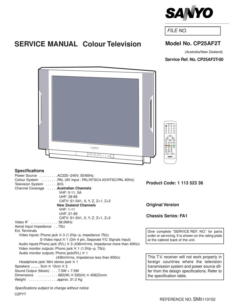
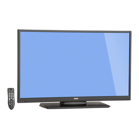
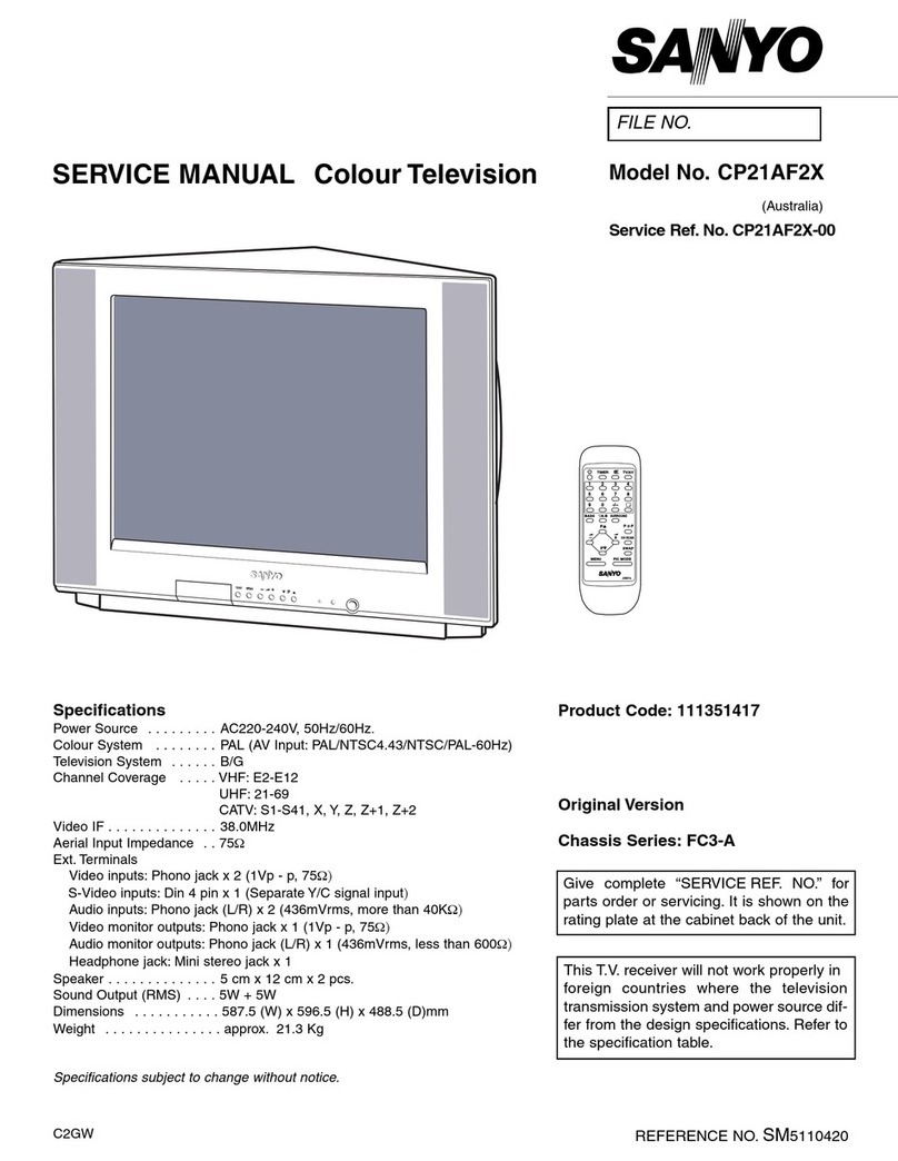
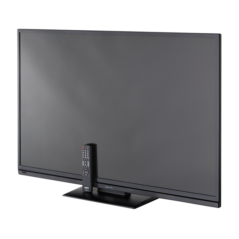
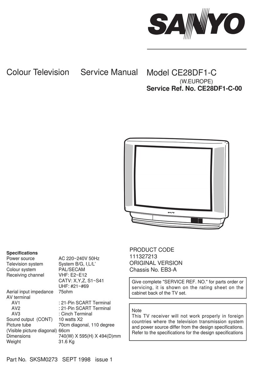
Sanyo DP42840 - 42" Diagonal LCD FULL HDTV 1080p User manual

Specifications
POWER RATING . . . . . . . . . . . . . . . . . . . . . . . . . 120VAC
178 W (AVG.)
ANTENNA INPUT IMPEDANCE. . . . . . . . . . . . . . . . . 75Ω
UHF/VHF/CATV
DIGITAL
RECEIVING CHANNEL . . . . . . . . . . . . . . . . . 2 - 13 (VHF),
14 - 69 (UHF),
01, 14-94, 95-135 (CATV)
1-135 (DIGITAL)
REMOTE READY. . . . . . . . . 36 KEY REMOTE CONTROL
SOUND OUTPUT. . . . . . . . . . . . . . . . . . . . . . . 10.0 W/CH
INTERMEDIATE FREQUENCY
PICTURE IF CARRIER . . . . . . . . . . . . . . . . . . 45.75MHz
SOUND IF CARRIER . . . . . . . . . . . . . . . . . . . 41.25MHz
COLOR SUB CARRIER . . . . . . . . . . . . . . . . . 42.17MHz
CABINET DIMENSIONS
WIDTH . . . . . . . . . . . . . . . . . . . . . . . . . . . . . . . 1012mm
HEIGHT . . . . . . . . . . . . . . . . . . . . . . . . . . . . . . . 704mm
DEPTH INCLUDING BASE . . . . . . . . . . . . . . . . 307mm
REFERENCE No. SM780178
DP42840, N7AP, PRODUCT CODE 113018210
FILE NO.
SERVICE MANUAL Remote Control Digital
Color Television DP42840 (U.S.A.)
(CANADA)
ORIGINAL VERSION
Chassis No. P42840-05
NOTE: Match the Chassis No. on
the unit’s back cover with
the Chassis No. in the
Service Manual.
If the Original Version
Service Manual Chassis
No. does not match the
unit’s, additional Service
Literature is required. You
must refer to “Notices” to the
Original Service Manual
prior to servicing the unit.
Servicing should be performed by only trained and qualified service personnel.
Contents
SAFETY INSTRUCTIONS. . . . . . . . . . . . . . . . . . . . . . . . . 2
SERVICE ADJUSTMENTS . . . . . . . . . . . . . . . . . . . . . . . . 3
ON-SCREEN SERVICE MENU . . . . . . . . . . . . . . . . . . . . . 4
POWER FAILURE CIRCUIT . . . . . . . . . . . . . . . . . . . . . . . 5
MECHANICAL DISASSEMBLY . . . . . . . . . . . . . . . . . . . . 6
CHASSIS ELECTRICAL PARTS LIST . . . . . . . . . . . . . . . . 8
COMPONENT AND TEST POINT LOCATIONS . . . . . . 21
BLOCK DIAGRAM POWER LINES. . . . . . . . . . . . . . . . . 25
BLOCK DIAGRAM SIGNAL LINES . . . . . . . . . . . . . . . . 26
IC BLOCK DIAGRAMS . . . . . . . . . . . . . . . . . . . . . . . . . . 27
TROUBLESHOOTING FLOW CHARTS . . . . . . . . . . . . . 33
MAIN IC(SIGNAL PROCESSOR) & PERIPHERICALS . . 36
SCHEMATIC NOTES . . . . . . . . . . . . . . . . . . . . . . . . . . . 37
IC, DIODE, AND TRANSISTOR PIN LAYOUTS. . . . . . . 38
PC BOARD CONNECTIONS AND LOCATIONS . . . . . . 39
CAPACITOR AND RESISTOR CODE CHART . . . . . . . . 40
SCHEMATIC DIAGRAMS. . . . . . . . . . . . . . . . . . . . . . . . 41
© Sanyo Manufacturing Corporation 2011

– 2 –
SAFETY PRECAUTIONS
WARNING: The chassis of this receiver has a floating
ground with the potential of one half the AC line voltage in
respect to earth ground. Service should not be attempted by
anyone not familiar with the precautions necessary when
working on this type of equipment.
The following precautions must be observed:
1. An isolation transformer must be connected in the power
line between the receiver and the AC line before any ser-
vice is performed on the receiver.
2. Comply with all caution and safety-related notes provid-
ed inside the cabinet, on the chassis, and on the back.
3. When replacing a chassis in the cabinet, always be certain
that all the protective devices are installed properly, such
as control knobs, adjustment covers, shields and barriers.
4. Before replacing the back cover of the set, thoroughly
inspect the inside of the cabinet to see that no stray parts
or tools have been left inside.
Before returning any television to the customer, the
service technician must perform the following safety
checks to be sure that the unit is completely safe to
operate without danger of electrical shock.
ANTENNA COLD CHECK
Remove AC plug from the 120 VAC outlet and place a
jumper across the two blades. Connect one lead of an ohm-
meter to the jumpered AC plug, and touch the other lead to
each exposed antenna terminal (UHF and VHF antenna ter-
minals). The resistance must measure between 1M ohm and
5.2M ohm. Any resistance value below or above this range
indicates an abnormality which requires corrective action.
LEAKAGE CURRENT CHECK
Plug the AC line cord directly into a 120 VAC outlet. (Do not
use an isolation transformer for this check.) Use an AC volt-
meter, that has 5000 ohms per volt or more sensitivity.
Connect a 1500 ohm 10 watt resistor, paralleled by a 0.15 μF
150 VAC capacitor, between a known good earth ground
(water pipe, conduit, etc.) and all exposed metal parts of the
cabinet (antennas, handle bracket, metal cabinet, screw
heads, metal overlays, control shafts, etc.). Measure the AC
voltage across the 1500 ohm resistor. The AC voltage
should not exceed 750 mV. A reading exceeding 750 mV
indicates that a dangerous potential exists. The fault must
be located and corrected. Repeat the above test with the
receiver power plug reversed.
NEVER RETURN A RECEIVER TO THE CUSTOMER
WITHOUT TAKING THE NECESSARY CORRECTIVE ACTION.
PRODUCT SAFETY NOTICE
When replacing components in a receiver, always keep in
mind the necessary product safety precautions. Pay special
attention to the replacement of components marked with a
in the parts list and in the schematic diagrams. To ensure
safe product operation, it is necessary to replace those com-
ponents with the exact same PARTS.
SERVICING ELECTROSTATICALLY SENSITIVE DEVICES
Semiconductors (solid-state devices) that can be damaged
by static electricity are referred to as Electrostatically
Sensitive (ES) devices. Examples of typical ES devices are:
Integrated Circuits (IC), Field-Effect Transistors (FET), and
“chip” components. The following techniques should be
observed strictly, to reduce the occurrence of semiconduc-
tor damage due to electrostatic discharge.
1. Immediately prior to handling any semiconductor com-
ponent or an assembly containing a semiconductor
device or devices, discharge the electrostatic buildup on
your body by touching a known earth ground. You may
also obtain and wear a commercially available discharg-
ing wrist strap device.
CAUTION: Be sure to remove the wrist strap before
applying power to any unit being serviced.
2. After removing an ES equipped assembly, place it on a
conductive surface, such as, aluminum foil, to prevent
buildup or exposure to static electricity.
3. Use only grounded-tip soldering irons to solder or unsol-
der ES devices.
4. Use only anti-static solder removal devices. Some suc-
tion-type devices can generate static electricity adequate
to damage ES devices.
5. A replacement ES device will come packaged in protective
material (conductive foam, aluminum foil, or some compa-
rable conductive material). Do Not remove an ES device
from its protective packaging unless you are prepared to
install it immediately.
6. Precisely prior to removing an ES device from its protective
packaging, touch the protective packaging to the chassis or
assembly in which the device will be installed.
CAUTION: Be sure that no power is applied to the chassis
or circuit assembly.
7. Incidental body movements, such as, lifting a foot from
a carpeted floor or the rubbing of fabric together can
generate static electricity sufficient to damage ES devices.
Therefore, minimize all body movements while handling
exposed (unpackaged) ES devices.
SAFETY INSTRUCTIONS

– 3 –
SERVICE ADJUSTMENTS
GENERAL
This set has an On-screen Service Menu system included in
the CPU that allows remote operation for most of the
service adjustments.
ON-SCREEN SERVICE MENU SYSTEM
1. Enter the Service Menu:
•Turn off the receiver and disconnect the AC power
supply.
•While pressing the Volume (––) button on the televi-
sion, reconnect the AC power supply. The Service
Menu will now appear. The remote can now be used
to make adjustments. See Figure 1 below.
2. Service Adjustments:
•Press the Cursor and key to select the desired
service menu item you want to adjust. See page 4 for
the On-screen Service Menu.
•Use the Cursor or key to adjust the data.
The or key will increase or decrease the data
sequentially.
3. Exit from the Service Menu:
•Press the MENU key to turn off the Service Menu
display.
Figure 1. Service Menu Display
HEX DATA
Index ParameterName
FACTORY_VOL 0x21 48 0 255
Value Def. MIN MAX
1
ITEM NO. TITLE
SUB CH
INFO DYN VOL
Menu:
Exit Service Menu
Cursor :
Select Item
Cursor :
Adjust the data
POWER
INPUT
ENTER
MENU
VOL
CH
POWER
INPUT
ENTER
MENU
VOL
CH
Volume – :Enter Service Menu

– 4 –
ON-SCREEN SERVICE MENU
Table 1. ON-SCREEN SERVICE MENU
When IC5750 (Flash Memory) is replaced, check the bus data to confirm they are the same as below. See page 3 for
On-Screen Service Menu access and adjustments.
PROGRAM CODES
The microprocessor used in this model is a multi-purpose type and is used in several different models. To ensure
proper operation and the correct features for your particular model, the program codes must be correct.
Note 1. Option Data 1 (NO. 087 OP1) should be hexadecimal
00. See 087 above. If this program code is wrong the TV will
not operate properly.
Note 2. Option Data 2 (NO. 088 OP2) should be hexadecimal
11. See 088 above. If this program code is wrong the TV will
not operate properly.
No. Title Initial Data Note
1A0 MUTE A0h Audio mute at Power ON
086 VOL 30h Volume setup inspection
087 OP1 00h Option 1 Data (HDMI)
088 OP2 11h Option 2 Data (Display Panel)
101 1R00 00h ROM Correction Data
102 1R01 00h ROM Correction Data
↓↓ ↓ ↓
197 2R47 00h ROM Correction Data
198 2R48 00h ROM Correction Data
• All data except in gray box area is fixed. Do not change for correct operating.
• Data in gray box is initial and can be set according to adjusment information.

– 5 –
POWER FAILURE CIRCUIT
Check the following if the unit is turned off by the power
failure detector.
1. Disconnect the AC power cord (120V AC line) for a short
time.
2. Connect a DC Voltmeter to the circuits shown below.
3. Press the Power key and check for the proper voltage
supplies.
4. If any of these voltages is low, the power failure detec-
tor should turn the unit off within three seconds.
5. Check all circuits shown below.
Note: If power failure is detected 3 times in 15 minutes,
the set will enter the standby mode and cannot be
switched On.To reset the operating programs of the
sub_CPU it is necessary to disconnect the AC cord
for a short time.
Internal sub_CPU on main IC 5500 is programmed so the
set will go to standby mode when there is circuit failure as
described below. (Refer to“Block Diagram Power Lines”.)
This unit is equipped with a Power Failure Detector function
included in the sub_CPU which checks for an abnormal
condition in the chassis power supplies.
If, while the power is on, a failure is caused by any of the fol-
lowing that results in a low voltage supply, the sub_CPU will
turn the unit off in 1.5 seconds to prevent further damage:
•Failure within the power supply circuits.
•A short circuit in the load side from the supply.
Power Failure: Detected voltage failure for circuit.
(Connected to IC5500 pin D9, through RB5501.)
(Normal: High; Failure: Low)
If, while the power is off, the power is switched on and any
of these failures remains uncorrected, the sub_CPU will
shut off the power within three seconds.
D9
D5
IC5500 (sub_CPU)
Power Fail
Power On1
Power Board
Main
D1668
K8B
D1641
D6700
Audio_Pow
12V
9V
5V
D1613
5V
Other manuals for DP42840 - 42" Diagonal LCD FULL HDTV 1080p
2
Table of contents
Other Sanyo TV manuals

Sanyo
Sanyo PDP-42XR8DA User manual

Sanyo
Sanyo CP14SA1 User manual

Sanyo
Sanyo CP25ST3T User manual

Sanyo
Sanyo CE25DN3-B User manual

Sanyo
Sanyo CPP2510 User manual

Sanyo
Sanyo CE25B3-C User manual

Sanyo
Sanyo DP46812 User manual

Sanyo
Sanyo CP21XS2 User manual

Sanyo
Sanyo CE21DN6F-C User manual

Sanyo
Sanyo DP50741 User manual

Sanyo
Sanyo CP14KX2 User manual

Sanyo
Sanyo DP50749-02 User manual

Sanyo
Sanyo DP15647 User manual

Sanyo
Sanyo DS31590 User manual

Sanyo
Sanyo LCD-32XR11F User manual

Sanyo
Sanyo CW21CF1 User manual

Sanyo
Sanyo LCD-37XR1 User manual

Sanyo
Sanyo CP14SE1 User manual

Sanyo
Sanyo DS35224 User manual

Sanyo
Sanyo C29LF34 User manual