SARA Ultra Cleaner UC1SD/S3 Manual

Bedienungs- und
Wartungsanleitung
perating and
Maintenance Instructions
Modelle/Models:
SARA®Ultra Cleaner UC1SD/S3, UC2SD/S3, UC3SD/S3
Auftrags-Nr.
rder No.
Stand 05/2012
As of 05 / 2012

Inhaltsverzeichnis
Table of Contents
ATTENTI N:
Please read all chapters of
this manual carefully before
commencing any installation
or maintenance work!
ACHTUNG:
Bitte lesen Sie alle Punkte dieses Hand-
buches sorgfältig, bevor Sie mit
Installations- oder Wartungsarbeiten
beginnen!
2
Allgemeine Beschreibung
General Description 3
Sicherheitshinweise
Safety Notes 4
WARNUNG
WARNING N TES 5
Installation des Gerätes
Installation of the Equipment 6-8
Aufbau und Funktionsbeschreibung
Setup and Functional Description 9-10
Technische Daten
Technical Data 11
Elektrischer Anschluss
Electrical Connection 12-16
Reinigung und Wartung
Cleaning and Maintenance 17-28
Ersatzteilliste
Spare Parts List 29-30
Installationsprüfliste
Installation Check List 31
Herstellererklärung
Manufacturer’s Declaration 32

3
➜Aerosol
Dispersionen von Fluidtröpfchen
und Feststoffteilchen in gasförmiger
Umgebung vorkommen.
➜Nebel
Fluidtröpfchen, die aus übersättigtem Dampf
bei Temperatur/Druckabsenkung durch
Kondensieren entstehen bzw. vorhanden sind.
Allgemeine Beschreibung
General Description
SARA®Ultra-Cleaner sind geeignet zur Abscheidung
von Schadstoffen, die in der Luft in Form von:
Die Geräte werden als anschlussfertige Einheit mit integriertem Ventilator geliefert. Das Gehäuse ist
stabil und verwindungsfrei aus Chromstahl lackiert in RAL 7035. Vier Füße mit Bohrungen erleichtern
die nstallation des Gerätes. Durch Schnellverschlüsse in der seitlichen Wartungstür ist ein einfacher
Zugriff auf die Filterelemente gewährleistet. Am Bodenteil befindet sich eine mit einer 1-Zoll-Muffe und
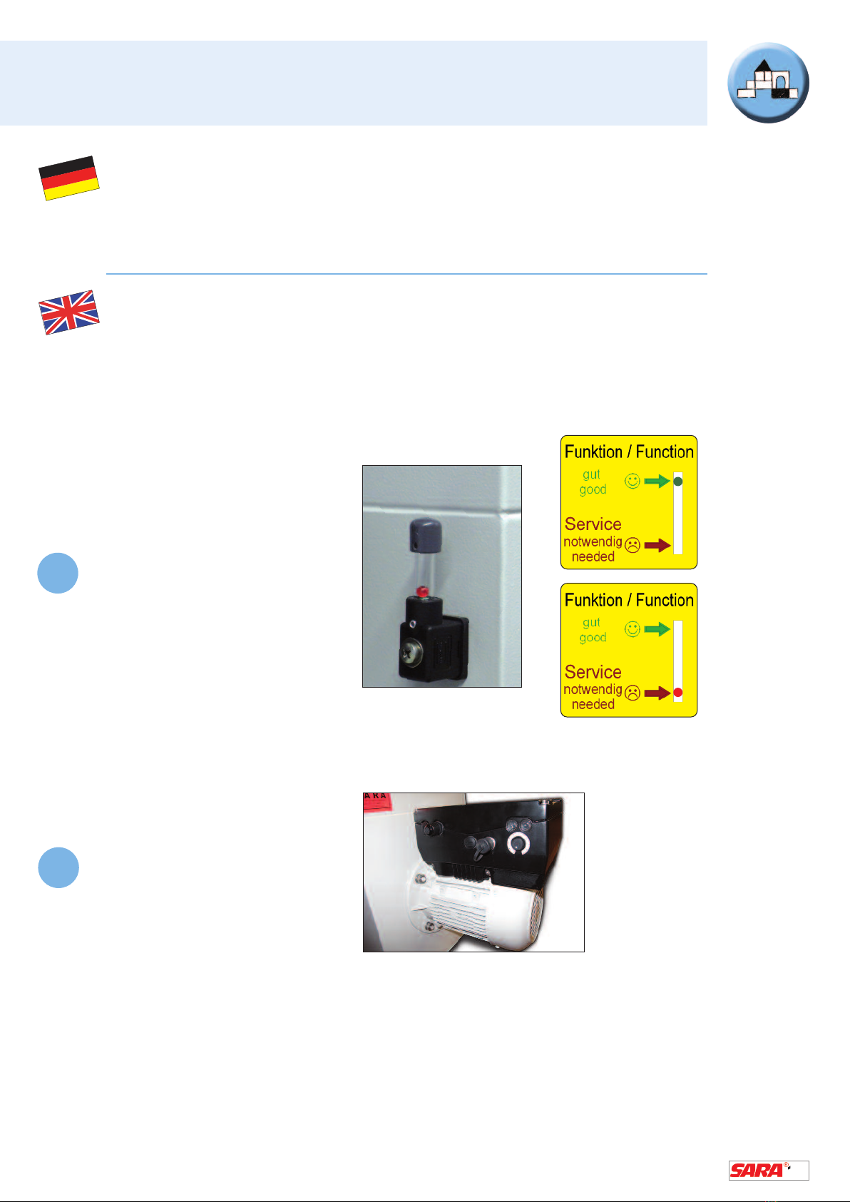
Kugelhahn versehene öl- und wasserdichte Sammelwanne. Die am Gerät angebrachte Funktionsanzeige
zeigt den Verschmutzungsgrad des mehrstufigen Hochleistungsabscheidersystems an. Aerosole und
Flüssigkeitspartikel werden mechanisch durch das patentierte X-Cyclone®Grundelement Typ RXZ
abgeschieden. Über weitere Filterstufen werden mithilfe von Hochleistungsagglomeratoren feinste
Aerosole agglomeriert, sodass eine Abscheidung kleinster Tröpfchen gewährleistet ist.
➜ Alle Grundelemente und Agglomeratoren können abgereinigt
und wiederverwendet werden, keine Wegwerffilter!
Für besonders hohe Ölnebelbelastungen ist das Gerät
optional mit Schwebstoff- oder Elektrostataufsatz nachrüstbar.
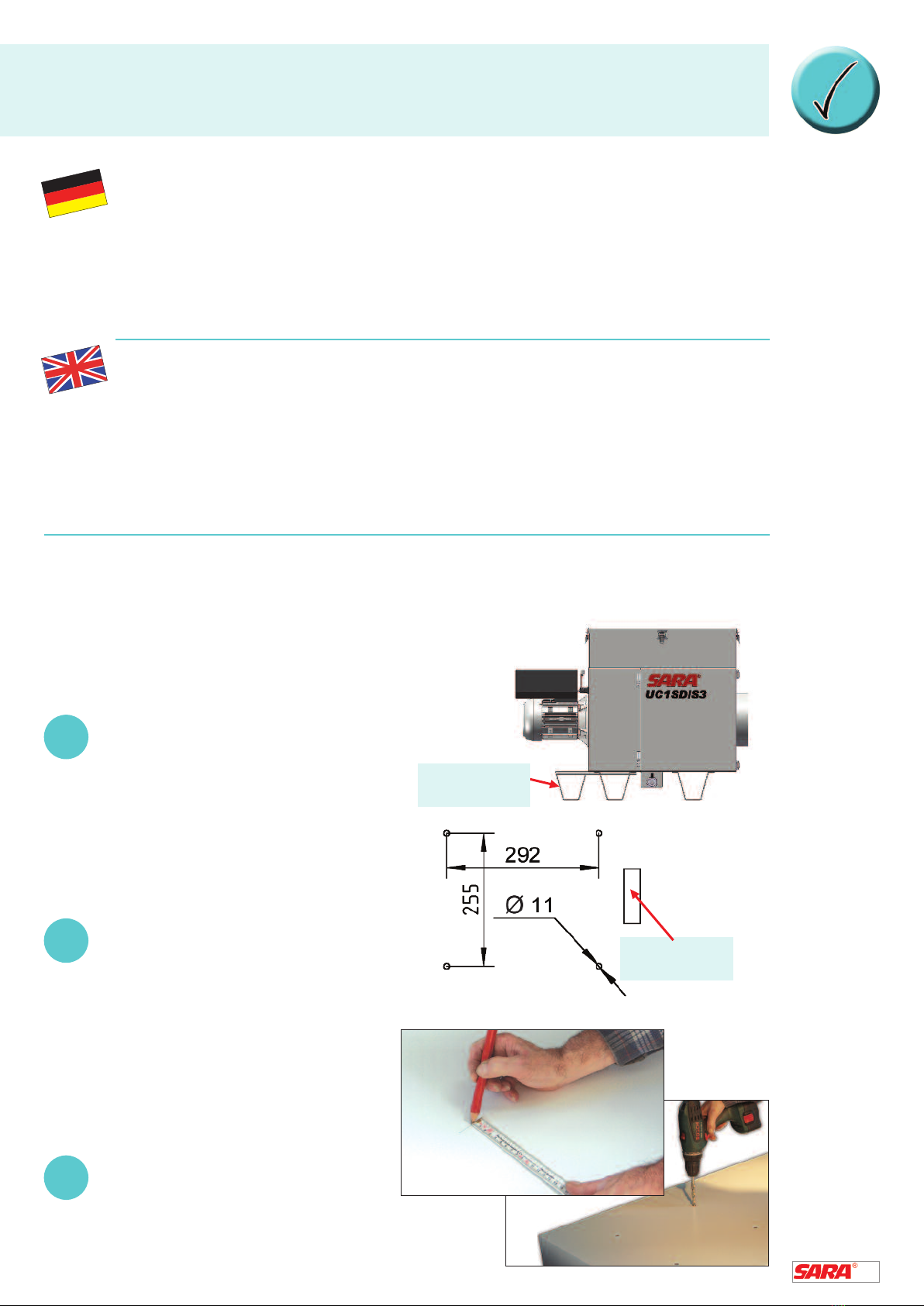
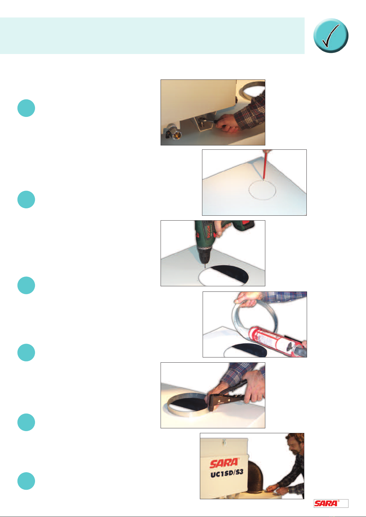
Die nstallation (siehe S. 6-8) der Geräte auf der Maschine
wird in dieser Bedienungsanleitung gesondert beschrieben.
SARA®Ultra Cleaners are suitable for the separation
of air pollutants such as:
The devices are delivered ready for connection with an integrated fan. The stable and torsion-free
housing is made of chrome steel with a lacquer finish in RAL 7035. Four supports with drill holes facilitate
the installation of the device. The clip fasteners in the lateral maintenance door ensure easy access to
the filter elements. The bottom part is equipped with an oil and watertight collecting tray that is fitted with
a 1 inch sleeve and a ball cock. The maintenance indicator fitted to the device indicates the degree of
pollution of the multi-stage high-performance separating system. Aerosols and liquid particles are
mechanically separated by the patented X-Cyclone®basic element type RXZ. With additional filter stages,
the finest aerosols are agglomerated using high-performance agglomerators to ensure that even the
smallest droplets are separated.
➜ All basic elements and agglomerators can
be cleaned and reused – no throwaway filters!
n the event of particularly high pollution with oil mist, you can
retrofit the device with an optionally available electrostatic collector
top unit or a submicron particulate filter top unit. The installation of
the device is described separately on the pages 6 to 8 of this manual.
Alle SARA®
Ultra-Cleaner
entsprechen
der europäischen
ErP Richtlinie!
➜Aerosol
Dispersions of fluid droplets
and solid particles in a gaseous
environment.
➜Mist
Fluid droplets generated from supersaturated
vapor through condensation when the
temperature/pressure drops.
All SARA®
Ultra Cleaners
comply with
the European
ErP directive!

4
ACHTUNG:
Einsatz der Geräte in explosionsgefährdeter Umgebung
Die Abscheidegeräte werden ohne Explosionsschutz ausgeliefert. Dies bedeutet,
dass keine Dämpfe, Gase und Nebel abgesaugt werden dürfen, die im Gerät
➜ explosionsfähige Medien bilden oder selbst sind.
Absaugen von Medien mit niedrigem Flammpunkt
Durch die zunehmende Verwendung von Öl mit einem niedrigeren Flammpunkt auf
modernen Werkzeugmaschinen, ➜ nimmt das Brand- und Verpuffungsrisiko bei
der Werkstoffverarbeitung generell zu. Wenden Sie sich im Zweifelsfall an
Fachfirmen für Brandschutzberatung und Brandschutzanlagen.
ATTENTI N:
Use of the devices in environments with a high risk of explosion
Our separators are delivered without explosion protection. This means that no vapors,
gases and mists may be extracted that are explosive or might form ➜ explosive media
inside the device.
Extraction of media with low ignition points
The steady increase in the use of oil with a low ignition point in modern machine tools
provokes a ➜ generally increased risk of fire and explosion in the field of material
processing. n case of doubt, please contact a competent specialized provider of fire
protection consultancy services and equipment.
Sicherheitshinweise
Safety Notes

5
WARNUNG
WARNING N TES
Eine Reinluftrückführung ist beim Umgang mit besonders krebserzeug-
enden Gefahrstoffen nach § 15a der GefStoffV nicht erlaubt! Diese sind:
- 6-Amino-2-Ethoxynaphthalin
- 4-Aminobiphenyl und seine Salze
- Asbest
- Benzidin und seine Salze
- Bis(chlormethyl)äther
- Cadmiumchlorid (in atembarer Form)
- Chlormethyl-Methyläther
- Dimethylcarbamoylchlorid
- Hexamethylphosphorsäuretriamid
- 2-Naphthylamin und seine Salze
- 4-Nitrodiphenyl
- 1,3-Propansulton
- N-Nitrosaminverbindungen
- Tetranitromethan
- 1,2,3-Trichlorpropan
➜ In diesen Fällen müssen die Ultra Cleaner Geräte im Abluftbetrieb betrieben werden,
d. h. kein Rückführen der gereinigten Luft in den Aufenthaltsbereich von Menschen!
f any of the following hazardous substances is found in the
extracted air of the machine, the cleaned air may under no
circumstances be returned into areas where people congregate!
- 6-amino-2-ethoxynaphthalene
- 4-aminobiphenyl and its salts
- Asbestos
- Benzidine and its salts
- Bis(chlormethyl)ether
- Cadmium chloride (in respirable condition)
- Chloromethyl methyl ether
- Dimethylcarbamoylchloride
- Hexamethyl phosphoric acid triamide
- 2-naphtylamine and its salts
- 4-nitrodiphenyl
- 1,3-propane sultone
- N-nitrosamine compounds
- Tetranitromethane
- 1,2,3-Trichloropropane
➜ In these cases, the air extracted by the Ultra Cleaner devices must not be recirculated,
i. e. no cleaned air may be returned into areas where people congregate!

6
Installation des Gerätes I
Installation of the Equipment I
➜ Die SARA®Ultra-Cleaner müssen absolut waagerecht installiert werden.
➜ Der SARA®Ultra-Cleaner muss so aufgestellt werden, dass der Anschluss einer
Ölablaufleitung möglich ist.
➜ Des Weiteren ist zu beachten, dass der SARA®Ultra-Cleaner so installiert wird,
dass die Wartungstür zugänglich ist.
➜ SARA®Ultra Cleaners must be installed in an absolutely horizontal position.
➜ The SARA®Ultra Cleaner must be set up in such a way that it is possible
to connect an oil drain line.
➜ t should also be ensured that the maintenance door is easy accessible
after the installation of the SARA®Ultra Cleaner.
Installationsbeispiel – Direktmontage auf der Bearbeitungsmaschine:
Installation example – direct installation on top of the processing machine:
Die Montagehilfe dient zum Abstützen des
Gerätes bei Transport und Montage. Sie
kann nach der nstallation entfernt werden.
The assembling aid is used as a support
during transport and assembly. t can be
removed after the installation.
nstallationsstandort auswählen.
Bei Montage direkt auf der Bearbeitungs-
maschine Tragfähigkeit beachten.
Choose the place of installation.
When installing the device on top of
the processing machine, check first
the bearing capacity of the machine.
Bei Montage direkt auf der Bearbeitungs-
maschine Lochbild anzeichnen und bohren
Eventuell daruterliegende Einbauten /
Traversen beachten.
When you install the device directly
on top of the machine, line up the hole pattern
and drill accordingly. Pay attention to any
rails or built-in units underneath!
1
2
3
Ansaugstutzen
Air intake
Abb. zu 2
Fig. tem 2
Montagehilfe
Assembling aid

7
5
4
6
7
8
Installation des Gerätes II
Installation of the Equipment II
SARA®Ultra Cleaner mit Maschinen-
schrauben M10 befestigen.
Fasten the SARA®Ultra Cleaner
with machine screws M10.
Lage der Absaugöffnung festlegen.
Lochbild anzeichnen und ausschneiden
(Durchmesser siehe Gerätedaten).
Determine the position of the suction opening.
Line up the hole pattern and cut out the
opening (see the device specification for
the correct diameter).
Nietlöcher für Bundkragen bohren.
Drill the rivet holes for the collar.
Bundkragen mit öl- und säurebe-
ständigem Dichtungsmittel versehen.
Apply oil and acid-resistant
sealant to the collar.
Bundkragen vernieten.
Fasten the collar with the rivets.
Absaugschlauch montieren.
Mount the extraction hose.
9

8
Installation des Gerätes III
Installation of the Equipment III
Anschluss der Ableitungen:
Die 1-Zoll-Anschlüsse an den Abscheidern
müssen im Betrieb ➜ luftdicht verschlossen
sein, da sonst die Funktion der Abscheider
nicht gewährleistet ist.
Dies kann zum Beispiel durch den Anschluss
eines Siphons oder einer Ableitung, deren
Ende luftdicht in einem Auffangbehälter
mündet, erfolgen.
Die Siphonauslegung der Maße a und b wird
im Folgenden beschrieben: Die maximale
"Ölsäule" im Siphon hat eine Höhe von 2 x b.
Connection of the drain lines:
The one inch connections to the separators must be
➜ sealed airtight in order to ensure the perfect
function of the separators.
For this purpose, a siphon or drain line with an
airtight end in a collecting tank can be connected,
for example.
The dimensioning of the siphon with respect to
the sizes specified for a and b is described
below. The maximum oil column in the siphon
has a height of 2 x b.
Bei einer einfachen „Rohr-Schlauchableitung“ muss die vertikale Länge,
also der Höhenunterschied zwischen Gehäusemuffe und Schlauchende,
mindestens das Maß a betragen.
Vor der nbetriebnahme des Gerätes muss der Siphon bzw. der Auffangbehälter
mit Flüssigkeit gefüllt werden, damit diese ➜ luftdicht abgeschlossen sind.
n case of a simple pipe/hose drain, the vertical length, i.e. the difference
in height between the housing socket and the hose end, must at least be
equal to a.
Before putting the device into operation, seal the siphons and collecting tanks
with liquid to ensure their ➜ airtight closure.

9
Aufbau und Funktionsbeschreibung I
Setup and Functional Description I
SARA®Ultra-Cleaner werden als Einheit mit integriertem
Ventilator geliefert. Das Gehäuse ist stabil und verwindungsfrei aus
Chromstahl lackiert in RAL 7035. Wartungstür mit Schnellverschlüssen.
verschlüssen. Gehäuse innen glattflächig. Mehrstufiges Hochleistungs-
system. Am Bodenteil befindet sich eine mit einer 1-Zoll-Muffe und Kugel-
hahn versehene öl- und wasserdichte Sammelwanne. Aerosole und
Flüssigkeitspartikel werden mechanisch durch das patentierte X-Cyclone®
Grundelement Typ RXZ abgeschieden. Grundelement Typ RXZ
TÜV-geprüfter ➜ Flammdurchschlagschutz, nach den Richtlinien
der US-amerikanischen Underwriters Laboratories®.
The SARA®Ultra Cleaner is delivered with an integrated fan.
The stable and torsion-free housing is made of chrome steel with
a lacquer finish in RAL 7035. The maintenance door is fitted with clip
fasteners. Smooth internal housing surfaces. Multi-stage high-performance
system. The bottom part is equipped with an oil and waterproof collecting
tray that is fitted with a 1 inch sleeve and a ball cock. Aerosols and liquid
particles are mechanically separated by the patented X-Cyclone®basic
element type RXZ. The ➜ flame arresting capability of the basic element
type RXZ has been tested successfully by the German TÜV in compliance
with the directives of the American Underwriters Laboratories®.
Einbaurichtung!
Installation
position
Schalldämpfer / Sound absorber
Einschub 1 – 50 mm frei für optimale Filterbestückung
Rack 1 – 50 mm of free space for
the easy insertion of filters
Einschub 3 – X-Cyclone®Typ RXZ
Rack 3 – X-Cyclone®type RXZ
Öl-Ablauf / Oil drain
Ansaugstutzen / Air intake
Gerätefüße / Device supports
Einschub 2 – Agglomerator / Rack 2 – agglomerator
Funktionsanzeige / Maintenance indicator
Montagehilfe / Assembling aid
Ventilator / Fan
Elektrischer Anschluss / Drehzahlregler
Electrical connection / Speed control

10
Aufbau und Funktionsbeschreibung II
Setup and Functional Description II
Über weitere Filterstufen werden mithilfe von Hochleistungsagglomeratoren feinste
Aerosole agglomeriert, sodass eine Abscheidung kleinster Tröpfchen gewährleistet ist.
Alle Grundelemente und Agglomeratoren können abgereinigt und wiederverwendet werden,
➜ keine Wegwerffilter!
The finest aerosols are agglomerated via additional filter stages using high-performance
agglomerators to ensure that even the smallest droplets are separated. All basic
elements and agglomerators can be cleaned and reused ➜ no throwaway filters!
Die einseitig angebrachte
Funktionsanzeige signalisiert den
Verschmutzungsgrad der Abscheider.
The maintenance indicator fitted to one
side of the device indicates the degree
of pollution of the separators.
Am motorseitigen Potenziometer
ist eine stufenlose Änderung des
Volumenstroms möglich.
The potentiometer fitted to the
motor side allows a continuous
adjustment of the airflow rate.
1
2

11
Technische Daten
Technical Data
Typ Leistung P Strom I Nennspannung U Ventilatordrehzahl
Betriebspunktdaten Betriebspunktdaten des Motors in n min-1
in Watt in Ampere in Volt (50Hz)
Type Performance P Current I Nominal voltage U Fan speed
operating point value operating point value of the motor in n min-1
in Watts in Amperes in Volts (50Hz)
UC1SD/S3 500 1,3 3~400 2750
UC2SD/S3 880 2,3 3~400 2740
UC3SD/S3 1170 2,6 3~400 2820
* Volumenstrom max. bei sauberen Abscheidern
Volumenstrom min. bei stark verschmutzten Abscheidern bzw. langen Ansaugleitungen.
➜ Bitte beachten! Zulässige Umgebungstemperatur für alle Typen 0°C bis 40°C.
* Max. volume flow when the separators are clean.
Min. volume flow when the separators are severely polluted or the suction lines are very long.
➜ Please note! The admissible ambient temperature range is from 0 °C to 40 °C
for all types.
Typ Luftmenge*Höhe H Breite B Länge L Ø Anschluss RXZ Grund- ca. Gewicht
in m3/h in mm in mm in mm element in kg
min./ max. Höhe x Breite
Type Air flow*Height H Width B Length L Ø Connection RXZ Basic Approx.
in m3/h in mm in mm in mm Element weight
min./max. height x width in kg
UC1SD/S3 500 1000 640 360 865 200 330 x 330 44
UC2SD/S3 1000 2000 720 440 900 200 410 x 410 62
UC3SD/S3 2000 3000 800 520 945 300 490 x 490 93
+Null-Leiter
+Neutral phase
+Null-Leiter
+Neutral phase
+Null-Leiter
+Neutral phase
640
356,50 839
LL
BW
HH

12
Arbeiten an elektrischen Bauteilen /-gruppen dürfen ➜ nur von einer Elektrofachkraft
entsprechend den geltenden Vorschriften durchgeführt werden. Der Unternehmer oder
Betreiber hat ferner dafür zu sorgen, dass die elektrischen Anlagen und Betriebsmittel,
entsprechend den geltenden Vorschriften betrieben und instand gehalten werden.
Bei Arbeiten an elektrischen Bauteilen /-gruppen ist darauf zu achten, dass das Gerät mit
einem Reparaturschalter vom Netz getrennt und gegen Wiedereinschalten gesichert wird.
Die Geräte sind bereits anschlussfertig verdrahtet und wurden vor der Auslieferung sicher-
heitstechnisch überprüft. Sie entsprechen den VDE-Vorschriften.
ACHTUNG:
Der Ultra-Cleaner muss an den örtlichen Potenzialausgleich angeschlossen werden.
Örtliche Leitungen müssen gegen Überlast und Kurzschluss abgesichert sein.
➜ Drehrichtung beachten!
Der elektrische Anschluss erfolgt in der Standardversion über den Drehzahlregler mit
Klemmverschlüssen. Hierzu ist bauseits eine 5-adrige Leitung (L1, L2, L3, PE) zu verlegen.
➜ Null-Leiter ist erforderlich bei optionalen elektrostatischen Nachfiltern!
Bitte beachten Sie die folgende Anschlusspläne (s. Seite 15-16).
Any work on electrical components/units may only be carried out by ➜ electrical specialists
and must comply with applicable regulations. Furthermore, the contracting or operating
company must ensure that the electrical installations and working equipment are operated
and maintained in compliance with applicable regulations.
Before commencing any work on electrical components/units, make sure that you separate
the device from its power supply by means of a repair switch and secure it against
unintentional activation.
Our devices are wired ready for connection and their compliance with safety regulations was
tested prior to delivery. They comply with VDE directives.
ATTENTI N:
The Ultra Cleaner must be connected to the local potential equalization line. Local lines
must be secured against overload and short-circuits.
➜ bserve the direction of rotation!
As a standard, the electrical connection is realized with connecting terminals via the speed
control. The required 5-conductor supply line (L1, L2, L3, PE) shall be installed by the customer.
➜ Neutral-phase is necessary if optional after-filters will be installed.
Please observe the following connecting plans (see page 15-16).
Elektrischer Anschluss I
Electrical Connection I

13
Überprüfung der Ventilatordrehrichtung
ACHTUNG:
➜ Bitte unbedingt die richtige Ventilatordrehrichtung beachten. Das Gerät saugt aufgrund
der Ventilatorform immer durch den Ansaugstutzen an. Eine falsche Drehrichtung
bewirkt eine stark verminderte Leistung des Geräts und kann den Ventilatormotor
dauerhaft beschädigen.➜ Bei falschem Anschluss übernehmen wir keine Garantie!
➜ Prüfen Sie die Drehrichtung von der Befestigung des Motors ausgehend.
Der Ventilator dreht immer gegen den Uhrzeigersinn!
➜ Schutzbrille tragen!
Verification of the fan's direction of rotation
ATTENTI N:
➜Please observe the direction of rotation of the fan under all circumstances. The device
sucks the air always in through the air intake due to the shape of the fan. f the fan
runs in the wrong direction the performance of the device is considerably reduced
and the fan motor might be damaged or even destroyed.➜ ur guarantee does
not cover an incorrect connection of the fan!
➜Check the direction of rotation from the position where the motor is fixed.
The fan should always rotate counter clockwise!
➜ Use safety classes!
Prüfung der
Ventilator-Drehrichtung:
Vertification of the fan’s
direction of rotation:
Nach Entfernen des Schalldämpferschaums kann die
➜ Ventilatordrehrichtung ohne Gefahr geprüft werden!
After removal of the sound-absorbing cellular mat, you can
➜ safely check the direction of rotation of the fan!
ACHTUNG:
Unbedingt diese
Richtung einhalten!
ATTENTI N:
The fan must run in
direction of the arrow.
Elektrischer Anschluss II
Electrical Connection II

14
Elektrischer Anschluss III
Electrical Connection III
Dezentrales
Antriebssytem –
KFU-Tronik
Fig.: Local
drive system –
KFU Tronic
Elektrischer Anschluss erfolgt über den Frequenzumrichter (FU),
siehe Anschlussplan S. 15.
Electrical connection via the frequency converter (FC),
see connecting diagram page 15.
Elektrischer Anschluss erfolgt über den Anschlusskasten am Motor,
siehe Anschlussplan S. 16.
Electrical connection via the connection box at the motor,
see connecting diagram page 16.
Dezentrales
Antriebssytem –
KFU-Tronik
Fig.: Local
drive system –
KFU Tronic

15
Elektrischer Anschluss IV Anschlussplan mit Frequenzumrichter (FU)
Electrical Connection IV Connecting diagram with frequency converter (FC)
Anschlussplan / Connecting Plan
H. SART RIUS GmbH&Co.
Harkortstr. 54 / D 40880 Ratingen
Tel.+49 (0) 2102 / 44 00-0, Fax +49 (0) 2102 / 44 00-24
Datum / Date
Bearb./
Processed by
Gepr./
Revised by
Norm
Standard
Name / Name Titel / Title Ultra Cleaner UC1SD/S3, UC2SD/S3, UC3SD/S3
Projekt / Project Auftragsnr. / rder no.
Blatt / Sheet
Kunde / Customer
Frequenzumrichter
- am Gerät montiert
- elektrische Ansteuerung
erfolgt bauseits
Frequency converter
- mounted to the device
- electrical connection
by customer
Zuleitung 5 x 1,5 mm2
L1, L2, L3, PE (bauseits)
Supply line 5 x 1,5 mm2
L1, L2, L3, PE (by customer)
WICHTIG: Null-Leiter ist er orderlich ür
optionalen elektrostatischen Nach ilter!
IMPORTANT: Neutral phase required or
optional electrostatic ilter top unit!
Standard
Motoranschluss
Motor connection
für / for 3 400 V 50 Hz
˜

16
Elektrischer Anschluss V Anschlussplan mit Anschlusskasten
Electrical Connection V Connecting diagram with connecting box
Datum / Date
Bearb./
Processed by
Gepr./
Revised by
Norm
Standard
Name / Name Titel / Title Ultra Cleaner UC1SD/S3, UC2SD/S3, UC3SD/S3
Kunde / Customer Auftragsnr. / rder no.
Blatt / Sheet
Projekt / Project
REVEN Lüftungssysteme, Umwelttechnik GmbH
Ludwigstr. 16-18 / D-74372 Sersheim
Tel. +49 (0)70429 / 373-0, Fax +49 (0)7042 / 373-20
Anschlussplan / Connecting Plan
Potentialfreier Thermokontakt
für Motorschutz (max. 230 V 2 A)
Zero-potential thermal contract
for motor protection (230 V 2 A max.)
Motoranschluss
Motor connection
Sternschaltung
Star connection
für / for 400 V 50 Hz
bzw. / or 460 V 60 Hz
Ventilatormotor - Anschlusskasten Fan motor - connecting box
Zuleitung 7 x 1,5 mm2(bauseits)
Supply line 7 x 1.5 mm2(by customer)
H. SART RIUS GmbH&Co.
Harkortstr. 54 / D 40880 Ratingen
Tel.+49 (0) 2102 / 44 00-0, Fax +49 (0) 2102 / 44 00-24
Anschlussklemmen zum
Verbinden der Thermokontakte
Terminals for the connection of
the thermal contacts

17
Reinigung und Wartung der Abscheider
Weisen die X-Cyclone®-Grundelemente Typ RXZ (Aluminium-Filterstufe) oder die AGG
Agglomeratoren Verschmutzungen in Form von Verharzungen oder Filterkuchen auf,
sind diese mithilfe eines Hochdruckreinigers oder einer ndustriewaschmaschine
z. B. zu reinigen. Bei der Abscheidung von Medien, die wegen der möglichen Bildung
von Schimmelkulturen, Viren oder Bakterien eine mikrobiologische oder biologische
Gefährdung darstellen, müssen unbedingt
➜ regelmäßige, kurze Wartungs- und Reinigungsintervalle eingehalten werden.
➜ Zur Reinigung der Filteranlage empfehlen wir den biologischen Entöler Oil-Free V2000.
Cleaning and Maintenance of the Separators
f the X-Cyclone®basic elements type RXZ (aluminum filter stage) or the AGG agglomerators
show strong contamination in the form of gumming or filter caking, they should be
cleaned with the help of a high-pressure cleaner or an industrial washing machine, for
example. f the media to be separated constitute a biological or microbiological hazard
because they form mildew cultures, viruses or bacteria, for example, it is imperative that
➜ regular maintenance and cleaning cycles be observed in short intervals.
➜ We recommend the biological oil remover Oil-Free V2000 for the cleaning of the filter system.
Gehen Sie wie folgt vor: / Follow the instructions below:
Filtergerät ausschalten und vorm Öffnen der Wartungstür
mithilfe eines Reparaturschalters vom Netz trennen.
Switch off the filter device and separate it from the power supply
with the help of a repair switch before opening the maintenance door.
Wenn im Abscheider gesundheitsgefährdende Stoffe abgeschieden werden, muss vor
dem Öffnen der Wartungstür eine entsprechende Schutzausrüstung angelegt werden.
➜ Sonst besteht je nach Abscheidemedium Vergiftungs-,
Verätzungs- und/oder Verbrennungsgefahr.
f materials that are hazardous to your health are separated in the device,
put appropriate protective clothing on before you open the maintenance door.
➜ This helps to avoid burns, poisoning and / or caustic burns
depending on the nature of the separated medium.
Vorm Öffnen der Wartungstür Ventilatorstillstand abwarten.
Wait until the fan has stopped rotating before you open the maintenance door.
2
1
3
Reinigung und Wartung I
Cleaning and Maintenance I

18
Die Wartungstür öffnen und die Elemente
aus dem Gehäuse herausziehen.
➜ Um die Wartungsarbeit zu erleichtern,
kann die Wartungstür ausgehängt werden.
Open the maintenance door and extract
the elements from the housing.
➜ For easier access to the interior of the
device, unhinge the maintenance door.
Bei der Wiedermontage der Plattenebenen ist darauf zu achten, dass die Elemente in
die Dränageaufnahme ➜ richtig eingeführt werden und die ➜ Filterprofile vertikal
angeordnet sind.
When reassembling the plate levels, make sure that the elements are ➜ reinstalled correctly
into the drainage receiver and the ➜ filter profiles are in vertical position.
5
Reinigung und Wartung II
Cleaning and Maintenance II
4
Abb.: FEHLEN?!
Abb.: X-Cyclone®Grundelement
Fig.: X-Cyclone®basic element
Abb.: Einbau-Bsp. für ein RXZ-Grundelement
in einem SARA®Ultra Cleaner
Fig.: Assembly example of an RXZ basic element
in a SARA®Ultra Cleaner
Einbaurichtung!
Installation
position

Reinigung und Wartung III
Cleaning and Maintenance III
19
Das Gehäuse und die Ventilatorkammer sind bei jeder Wartung auf Sauberkeit zu prüfen.
ACHTUNG: Vorm Entfernen des Eingreifschutzes unbedingt
Ventilatorstillstand abwarten – Verletzungsgefahr!
Zur Reinigung empfehlen wir den biologischen Entöler Oil Free V2000. Besonders
wichtig ist die Sauberkeit des Ventilators. Verkrustungen an den Lüfterblättern führen zu
Unwucht und dauerhafter Beschädigung des Ventilatormotors. Starke Verkrustungen können
mithilfe einer weichen Bürste gelöst werden. Dazu wird der Ventilator mit Reven Oil-Free
V2000 eingesprüht und vorsichtig abgebürstet. Dieser Vorgang ist so oft zu wiederholen,
bis der Ventilator sauber ist.
The cleanliness of the housing and the fan chamber should be checked during each
maintenance intervention.
ATTENTI N: Wait until the fan has stopped rotating before you
remove the contact protection – risk of injury!
We recommend the biological oil remover Oil Free V2000 for cleaning operations.
The cleanliness of the fan is of particular importance. ncrustation on the fan blades will
produce imbalance and might damage or even destroy the fan motor. Strong incrustation
can be removed with the help of a brush. Spray Reven Oil Free V2000 onto the fan blades
and brush them carefully. Repeat this process until the fan is clean.
ACHTUNG:
➜ Auf keinen Fall harte Gegenstände, wie Spachtel oder Schraubenzieher,
zur Reinigung des Ventilatorsbenutzen – Beschädigungsgefahr!
Direktes Einwirken der Reinigungsflüssigkeit auf den Ventilatormotor vermeiden!
ATTENTI N:
➜ Never use any rigid tools such as scrapers or screw drivers
for the cleaning of the fan – risk of damage!
Avoid any direct action of the cleaning agent on the fan motor!
Motor / Motor
Ventilatorkammer / Fan chamber
Ventilatoreingreifschutz /
Fan contact protection

Reinigung und Wartung IV
Cleaning and Maintenance IV
Überprüfung der Türdichtung:
Die Türdichtung der SARA®Ultra Cleaner unterliegt einem Alterungsprozess.
➜ Bei Undichtheiten, Aushärtungen oder Beschädigungen muss die Türdichtung
ausgetauscht werden. Die Türdichtung ist auf das Rahmenprofil aufgesteckt –
➜ ein Auswechseln der Dichtung ist ohne großen Aufwand möglich!
Check the door seal:
The door seal of the SARA®Ultra Cleaner is affected by ageing.
➜ If any leakage, age hardening or damage becomes apparent, the door seal
must be replaced. The door seal is fitted onto the frame section –
➜and can easily be replaced!
ACHTUNG:
➜ Der Stoß der Dichtung muss immer oben sein. Die Dichtung zeigt mit den
drei Dichtungslippen immer zur abzudichtenden Seite (also zum nneren des Gehäuses)!
ATTENTI N:
➜ The butt joint of the seal must always be on top. The three sealing lips should
always face the side to be sealed (which is the housing interior).
Alte Dichtung entfernen.
Remove the old seal.
Neue Dichtung montieren.
nstall the new seal.
2
1
20
This manual suits for next models
2
Table of contents