manuals.online logo
Brands
  1. Home
  2. •
  3. Brands
  4. •
  5. Sarabec
  6. •
  7. Hearing Aid
  8. •
  9. Sarabec LA110 User manual

Sarabec LA110 User manual

SAFETY PRECAUTIONS
The manufacturer cannot be held responsible for damage which is caused by not using the Loop System in
compliance with the safety precautions.
Do not open casing of Loop Amplifier at any time; NO user serviceable parts can be found inside.
Ensure mains power is disconnected BEFORE any connections are made to the Loop Amplifier.
Do not expose the Loop Amplifier, cable and accessories to rain or any other source of moisture.
Ensure that there is enough room around the Loop Amplifier for ventilation purposes.
Do not place the Loop Amplifier close to sources of heat, such as radiators.
United Kingdom connection to mains supply
This apparatus must be protected by a 3amp fuse if a 13amp(BS1363) plug is used. Be sure to replace the fuse
only with an identical approved type, as originally fitted, and to replace the fuse cover.
IMPORTANT: The wires in this mains lead are coloured in accordance with the following code
Blue: Neutral Brown: Live.
If you need to change the mains plug supplied, the colours of the wires in the mains lead of this apparatus may
not correspond with the coloured markings identifying the terminals in your plug. Proceed as follows: The wire
which is coloured BLUE must be connected to the terminal marked with the letter N or coloured BLACK. The
wire coloured BROWN must be connected to the terminal which is marked with the letter L or coloured RED.
DO NOT make any connection to the terminal which is marked with the letter E or coloured GREEN.
IF IN DOUBT - SEEK EXPERT ADVICE
E
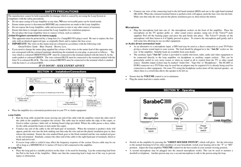
SECTION ‘A’ - Installation/Connections
Place the amplifier in a convenient position near to your TV or Audio equipment.
Loop Cable
Run the loop cable around the room, leaving one end of the cable with the amplifier, return the other end of
the cable to the amplifier (complete the circuit). The cable may be tucked under the edge of the carpet, or
fixed to either a picture / dado rail, or skirting board (clips provided). Where the cable passes a door, either
fix the cable around the frame or tuck under the carpet.
Connect both ends of the loop cable to the loop cable connectors, one wire in each connector.
If excess loop cable is coiled it may affect the frequency response of the system. Excess cable may be cut
off as long as a MINIMUM of 11 metres (35 feet) is left connected to the amplifier.
or Loop Pad
Place the loop pad in a suitable position on the chair to be used for listening. Lay the connecting lead from
the Pad to the back of the Amplifier. Make sure that the connecting lead is kept out of the way to prevent
injury or obstruction.
Attach the connecting lead to the loop cable connectors, one wire in each connector.
Note:
When the loop cable connector buttons are pushed a hole will appear, push the bare wire into the hole. Ensure
that only the wire and not the plastic insulation goes in, then release the button.
Microphone
Plug the microphone lead into one of the microphone sockets on the rear of the amplifier. Place the
microphone on the TV speaker grille, or other sound source speaker, using one set of the Velcro™ pads
supplied. Peel off the backing paper and press the pad firmly into place. The microphone will then fasten to
it if lightly pressed in place. To remove the microphone pull gently and it will come free allowing its use
on other equipment.
Audio direct connection lead
As an alternative to a microphone input, the auxiliary input “Aux In” sockets may be used to connect to the
audio outputs of a television, radio or other audio and video equipment.
Using the “Aux In” sockets will result in a clearer sound from your system where a microphone may pick
up unwanted sounds in noisy rooms or if the volume on the TV etc needs to be turned off or down.
These connecting leads should be plugged in to the “Aux In Left/Right” Phono/RCA sockets on the rear of
the amplifier. If the leads provided with your system are not suitable, other leads are available from your
dealer.
The SCART or EUROconnector on a TV/Video may be used but an adaptor may be required if it is already
being used for connection to other equipment, consult your dealer for advice if necessary
On some TVs using the headphone socket turns off the internal speaker, on others there is a switch that
allows the speaker to be left on.
In addition, to either the microphone or direct connection lead described above, a microphone may be used to
monitor a doorbell or telephone or used by another person to talk to the person using the loop.
Plug in the mains lead into the socket on the rear of the amplifier and then plug into the mains outlet.
SECTION ‘B’ - Operating
Before switching on ensure that the VOLUME control is set to MIN and the TONE control is set pointing
upwards, halfway between LOW and HIGH. Ensure that the ON/OFF , AGC and PRIORITY buttons are
‘Off’. These switches are pushed once for ‘Off’ and again for “On”. When the button is fully out it is ‘Off’.
Switch on the amplifier by pressing the ON/OFF button. The green power light will come on.
Set the television or other audio equipment to the normal listening level for other members of your household,
switch your hearing aid to the “T” or “MT” position.
Adjust the loop amplifier VOLUME control for the best results in your normal viewing position.
Adjust the TONE control to suit. In the “HIGH” position (fully clockwise), the higher frequencies will be
emphasised. In the “LOW” position (fully anticlockwise) the lower frequencies will be emphasised.
Aux In
Left
Right
Loop Amplifier
Model: LA110
Serial No:
Sarabec Ltd., Middlesbrough
Made in UK
230V~ 50Hz 20 VA Max
Microphones
Loop Cable
0.5 - 1.5 Ohms
AB
DO NOT OPEN
No user serviceable
parts inside.
230 Volt AC Mains
Power Lead Socket
Loop Cable or
Loop Pad
connectors
Microphone input
sockets (3.5mm
mono jack)
Auxiliary input sockets
(Phono/RCA) for direct
lead connections to TV or
HiFi etc.
ON/OFFVOLUMETONE
HIGHLOW MIN MAX
Loop Amplifier
Tone Control Volume Control Power "ON" light
Power
"ON/OFF"
switch
SECTION ‘C’ - Problems and Cures
Symptom Possible cause and remedy
No sound. Re-check all connections. Check diagrams.
Amplifier not switched on. Switch on at mains socket. Press mains switch.
Check green LED light is on.
Microphone not plugged in or other audio source not connected.
Hearing aid not on “T/MT” or “T” facility not working.
Low sound. Microphone too far from sound.
Loop cable wired incorrectly. Check diagrams.
Volume control set too low. Turn up volume on amplifier.
Radio or TV volume set too low. Turn up volume on Radio or TV.
Distorted sound Loop Volume control too high. Turn volume down.
Radio or TV volume set too high. Turn down volume on Radio or TV.
Move microphone away from loud speaker.
Microphone plug/lead damaged.
Background noise
(hum or buzz)
If noise remains when loop amplifier is turned off but hearing aid is still on
“T”, this is interference caused by other equipment such as TV, fluorescent
lights or dimmer switches. With the loop amplifier turned off and the hearing
aid still on “T” turn items off in turn until the noise goes away.
If noise stops when the loop amplifier is turned off there may be a fault in the
system or microphone lead or noise is being picked up by the microphone.
If in doubt please contact your dealer for assistance.
SECTION ‘D’ - Specification
Power Supply 230 V AC 20VA Max via Fig 8 mains lead.
Controls Rotary VOLUME control to vary the output level.
Rotary TONE control to vary the output tone.
ON/OFF push button switch.
Input connections 2 microphone inputs A/B. 3.5mm mono jack plug. DC powered for electret
microphones.
Aux In Left/Right line input. Phono/RCA sockets. For direct connection to a
TV sound output or other audio source via SCART or other suitable socket.
Output connections Push grip connectors for loop cable or loop pad (Labelled: Loop Cable). Loop
will give full output with loop resistance between 0.5 and 1.5 Ohms.
Loop output 2.85A output current @ 100-5kHz. Sufficient to meet BS6083 pt4 (IEC118-4)
in a loop not exceeding 6.25m(20ft) in width for most domestic si
t
uations.
Loop cable Single turn loop cable. Standard system supplied with 37m(120ft) 24/0.2
(0.75mm²) single core PVC insulated cable and cable clips. Minimum cable
length 11m = 0.5 Ohms.
Indicators Green Light Emitting Diode (LED) for Power On indica
t
ion.
Product conforms to the provisions of the following European Union Directives :
73/23 Low Voltage Directive
89/336 & 92/31 Electro Magnetic Compatibility Directives
is a mark of Sarabec Ltd. Sarabec Ltd 134-x1x.002 0304 LA110.doc
®
Home Loop System/Loop Pad System
Model LA110
Owner’s Manual
Introduction
The Sarabec LA110 Home Loop System provides a practical solution for hearing aid users to
listen more easily to their TV or Audio equipment via the “T” or “MT” facility of their aid.
With no direct connection between the user and the TV the user is able to move freely within
the looped area and listen comfortably to the TV or other equipment.
The Home Loop System is used in conjunction with a hearing aid with a switch position
marked "T" or "MT", this is found on most 'behind the ear' hearing aids. The system picks
up the sound from the TV via a microphone and feeds it to the amplifier. The amplifier
passes the sound to a loop of wire around the listening area, which in turn transmits the
sound inductively, “magnetic sound waves”, to the hearing aid. The user may then adjust the
loop volume to suit their own hearing preference without affecting other people.
The Home Loop System is supplied with Loop Cable to be placed around a room that you
want to listen in. The Loop Pad System is an alternative to the standard Home Loop System
creating either a portable loop system or a localised system where adjacent loop systems
could interfere with each other.
The Home Loop System is supplied ready for use with the following items.
1. LA110 Loop Amplifier.
2. Mains lead with fitted plug.
3. Microphone with Velcro™ pads
4. SCART to Phono direct connection lead
5. 37m(120ft) Loop Cable and pack of 50 cable clips
or
Loop Pad with 5m(15ft) connecting cable
6. Guarantee Card
7. Owners manual
Sarabec Limited 15 High Force Road Middlesbrough TS2 1RH UK
Telephone (01642) 247789 Fax (01642) 230827 Text (01642) 251310

Other Sarabec Hearing Aid manuals

Sarabec Crescendo 60 User manual

Sarabec

Sarabec Crescendo 60 User manual

Sarabec LA2c User manual

Sarabec

Sarabec LA2c User manual

Sarabec Loop System LA240 User manual

Sarabec

Sarabec Loop System LA240 User manual

Sarabec Crescendo 60 User manual

Sarabec

Sarabec Crescendo 60 User manual

Sarabec Neck Loops User manual

Sarabec

Sarabec Neck Loops User manual

Sarabec Crescendo 50 User manual

Sarabec

Sarabec Crescendo 50 User manual

Sarabec Neck Loop NL5 User manual

Sarabec

Sarabec Neck Loop NL5 User manual

Sarabec Loop System LA240 User manual

Sarabec

Sarabec Loop System LA240 User manual

Popular Hearing Aid manuals by other brands

Pyle PHLHA52 manual

Pyle

Pyle PHLHA52 manual

Phonak CROS user guide

Phonak

Phonak CROS user guide

SurfLink Media Troubleshooting

SurfLink

SurfLink Media Troubleshooting

Phonak Dalia user guide

Phonak

Phonak Dalia user guide

Starkey Wi Series Quick tips

Starkey

Starkey Wi Series Quick tips

Auria Harmony HiResolution Bionic Ear System quick start guide

Auria

Auria Harmony HiResolution Bionic Ear System quick start guide

Toshiba THA-1001 manual

Toshiba

Toshiba THA-1001 manual

Widex AIKIA AK-9 User instructions

Widex

Widex AIKIA AK-9 User instructions

Siemens Intuis 2 SP user guide

Siemens

Siemens Intuis 2 SP user guide

ANALOG HEARING LABS TrueEQ user manual

ANALOG HEARING LABS

ANALOG HEARING LABS TrueEQ user manual

Beurer HA 50 Instructions for use

Beurer

Beurer HA 50 Instructions for use

Widex The MENU ME-9 User instructions

Widex

Widex The MENU ME-9 User instructions

oticon BTE Alta2 Pro Instructions for use

oticon

oticon BTE Alta2 Pro Instructions for use

Phonak CROSLink user guide

Phonak

Phonak CROSLink user guide

Kirkland Signature SDS 4.0 reference guide

Kirkland Signature

Kirkland Signature SDS 4.0 reference guide

Starkey tour ric 312 Operation manual

Starkey

Starkey tour ric 312 Operation manual

Widex Bravissimo BV-38 User instructions

Widex

Widex Bravissimo BV-38 User instructions

oticon FittingLINK 3.0 user manual

oticon

oticon FittingLINK 3.0 user manual

manuals.online logo
manuals.online logoBrands
  • About & Mission
  • Contact us
  • Privacy Policy
  • Terms and Conditions

Copyright 2025 Manuals.Online. All Rights Reserved.