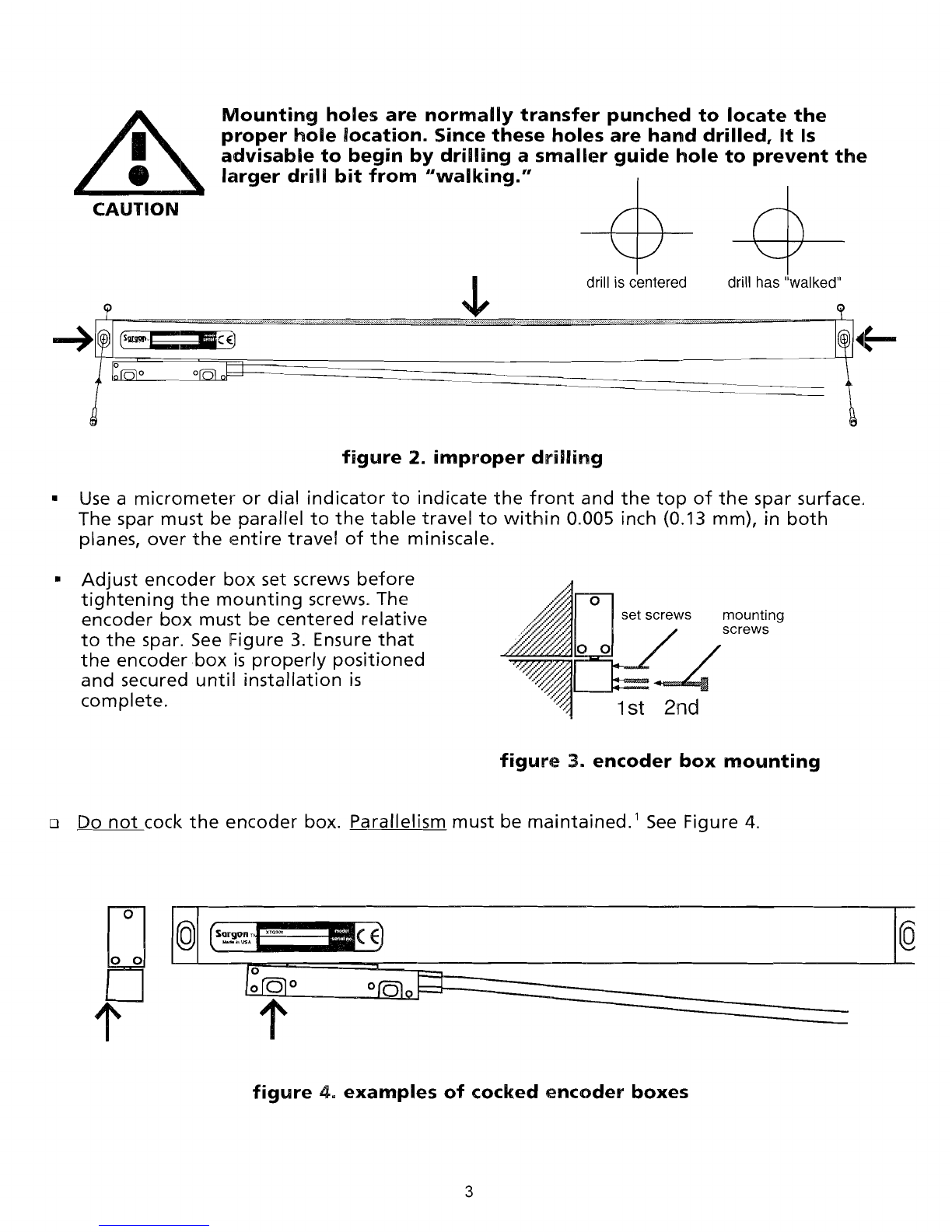
After
locating
the
mounting
area,
mark
both
ends using
the
ways as a reference
with
a
precision
instrument,
such as calipers.
Drill/tap
for
5/16-18 x 1-7/8 socket cap bolts.
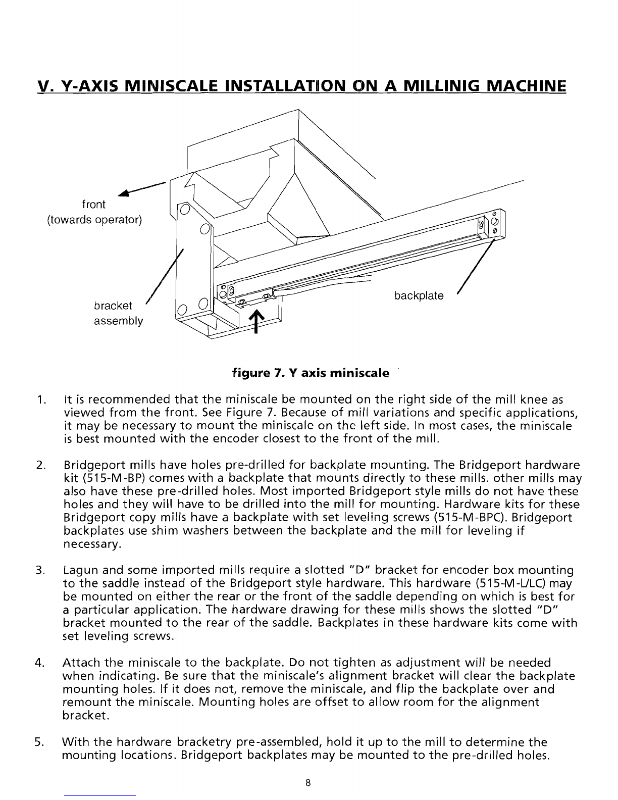
Mount
the
backplate
(with
the
miniscale
attached)
to
the
mill.
Verify
that
the
encoder
box
bracket
and
the
rest
of
the
bracketry
will
mount
to
the
encoder
box.
Adjust
the
backplate
for
parallelism using
the
leveling screws
(or
washer/shim
for
Bridgeport
hardware)
as necessary.
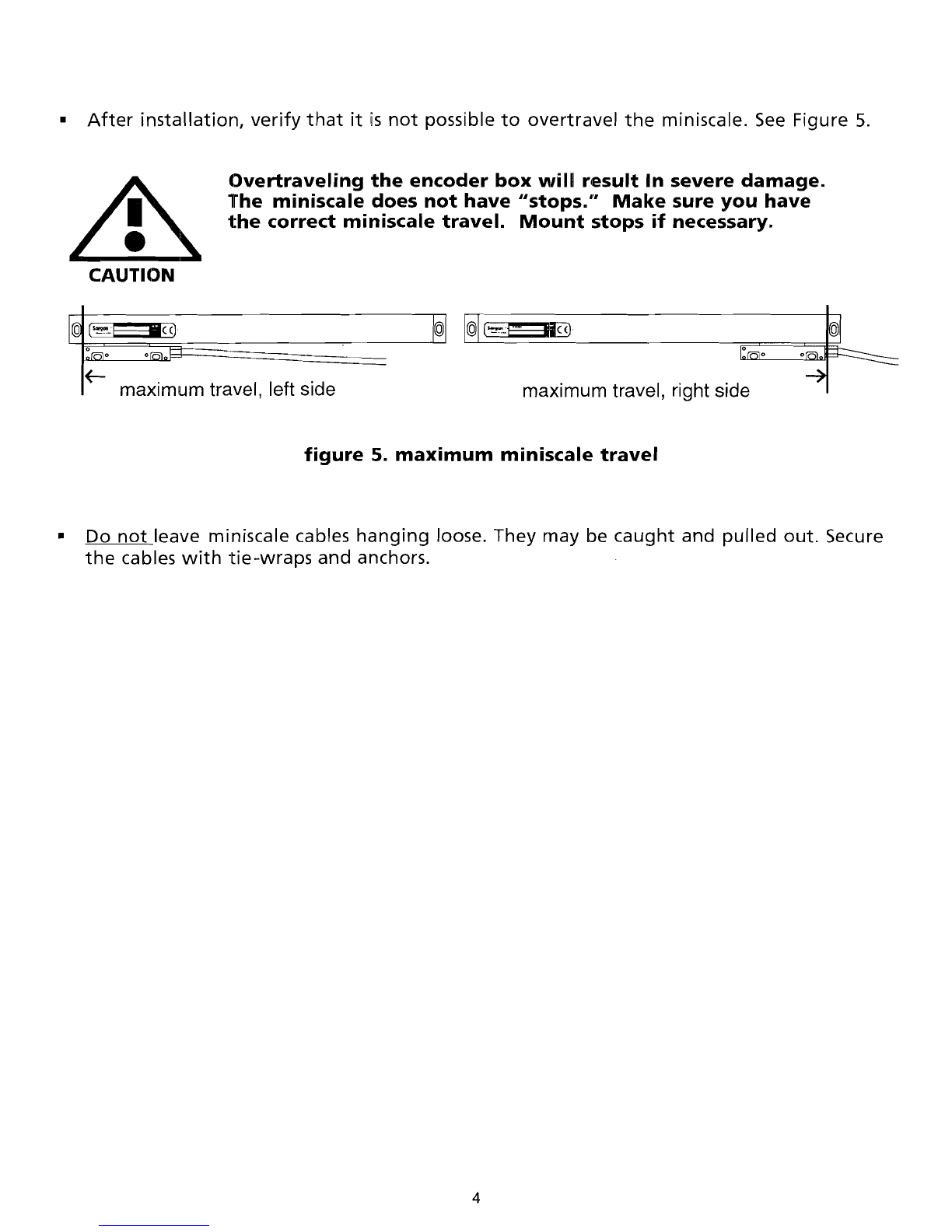
SETSCREWS
MUST
BE
PROPERLY
ADJUSTED. IMPROPER ADJUSTMENT
MAY
CAUSE
WARPING OR TWISTING OF THE BACKPLATE.
6.
Indicate
the
spar surface
(top)
with
respect
to
the
ways using a
depth
micrometer,
dial
indicator
or
calipers.
Adjust
the
two
miniscale ends so
that
the
spar surface is parallel
to
the
table
travel
within
0.005 inch (0.13 mm)
over
its
entire
travel.
Use
the
ways as a
reference.
Indicate
the
miniscale face housing surface
from
end
to
end
to
within
0.005
inch (0.13 mm)
over
its
entire
travel.
Adjust
the
backplate
and/or
miniscale using
the
leveling
screws
(or
washer/shim
for
Bridgeport
hardware)
as necessary.
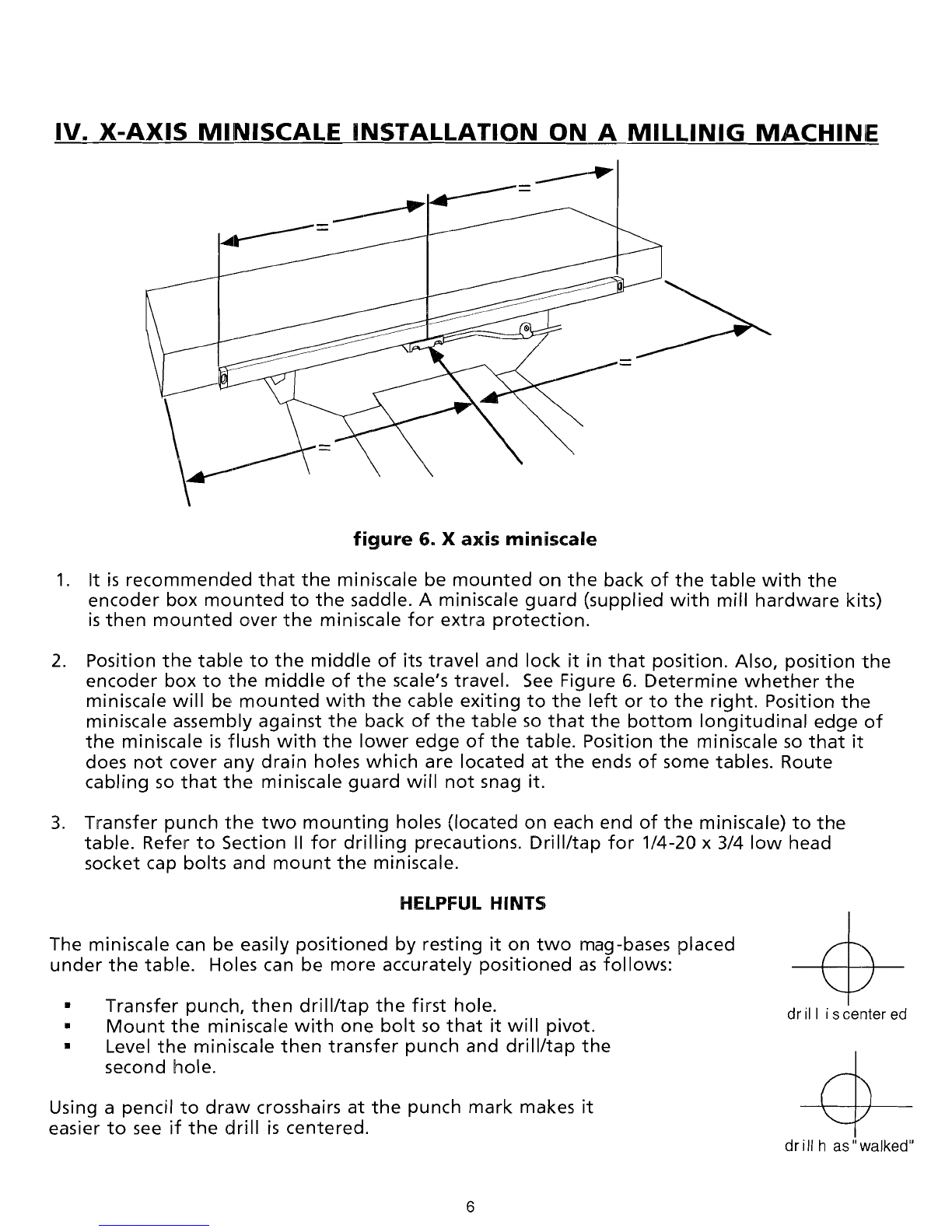
7. Position
the
table
fully
to
its end
of
travel
closest
to
the
operator
(standing
in
front
of
the
machine) and lock
it
into
position.
Position
the
encoder
box
to
the
end
of
its
travel
(towards
the
front
or
operator
side).
Mark
the
saddle
location
and
drill/tap
for
1/4-20 x
3/4 socket cap bolts.
Mount
the
bracket
assembly.
8. Encoder Box
Mounting:
a. Transfer punch
the
two
encoder
box
mounting
holes
to
the
bracket.
Drill/tap
for
8-32 x 3/4 socket cap screws.
b. Insert and
adjust
the
4
encoder
box
set screws (5-40)
until
they
just
touch
the
rnountinq
surface
Improper
adjustment
can
force
the
encoder
box
out
of
its
calibrated
position
and
cause
erratic
miniscale
performance
and
damage.
c.
Mount
the
encoder
box
with
the
two
8-32 x 3/4 socket cap screws. Do
not
overtighten
the
encoder
box
mounting
screws.
f. Release
the
table
lock
and move
the
Y axis
table
to
its
two
extreme
positions
while
monitoring
the
encoder
box
travel.
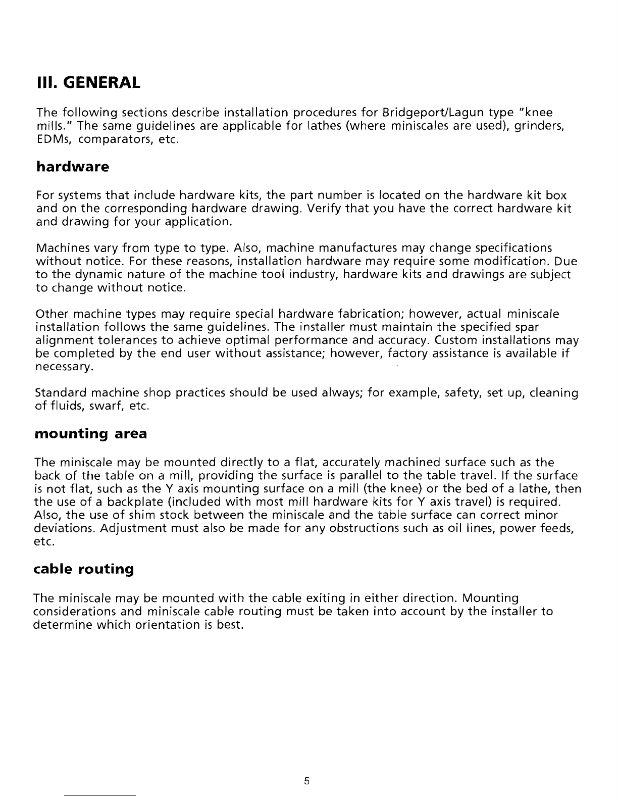
VERIFY THAT TBE MINISCALE CANNOT
BE
OVERTRAVELED. See Figure 5.
9. No miniscale
guard
is
provided
for
the
mill
Y axis since
the
miniscale is
mounted
underneath
the
saddle. However, an
optional
rniniscale
guard
may be
obtained
by
contacting
your
dealer
or
the
factory.
10. Route
and
secure
the
cables
to
the
display. Ensure
that
the
cables are
not
hanging
loose
to
be
caught
on any
part
of
the
machine
during
operation.
NOTE
Do
not
run miniscale cables parallel
with
power
wires. Induced noise
may
cause
the
display
to
miscount.
Maintain
a
minimum
of
6 inches
between
cables
and
cross
at
right
angles.
9