saro 447-2005 User manual

Betriebsanleitung Kühlaggregate (positiv/negativ)
Operating instructions for cooling units (positive/negative)
Deutsch
Übersetzung des Originals
English - Original
Betriebsanleitung für Best.-Nr.: 447-2000, 447-2005, 447-2010, 447-2020, 447-2025, 447-2030
Operating manual for Order No.: 447-2000, 447-2005, 447-2010, 447-2020, 447-2025, 447-2030
Bsp.: 447-2000
e.g.: 447-2000

Stand 03/2018 TM
2

3
Stand 03/20187 TM
3
INHALT / CONTENT
Beschreibung / Description. . . . . . . . . . . . . . . . . . . . . . . . . . . . . . . . . . . . . . . . . . . . . . . . . . . . . . . . . . . . . . . . . . . . . . . . . . . . 4
Identizierung / Identication . . . . . . . . . . . . . . . . . . . . . . . . . . . . . . . . . . . . . . . . . . . . . . . . . . . . . . . . . . . . . . . . . . . . . . . . . 4
Bedienung / Operation. . . . . . . . . . . . . . . . . . . . . . . . . . . . . . . . . . . . . . . . . . . . . . . . . . . . . . . . . . . . . . . . . . . . . . . . . . . . . . . . 5
Schematische Darstellung / Schematic Diagram . . . . . . . . . . . . . . . . . . . . . . . . . . . . . . . . . . . . . . . . . . . . . . . . . . . . . . . 6
Einsatzgrenzen / Operation limits. . . . . . . . . . . . . . . . . . . . . . . . . . . . . . . . . . . . . . . . . . . . . . . . . . . . . . . . . . . . . . . . . . . . . . 6
Zusammensetzung / Composition. . . . . . . . . . . . . . . . . . . . . . . . . . . . . . . . . . . . . . . . . . . . . . . . . . . . . . . . . . . . . . . . . . . . . 7
Tests / Tests . . . . . . . . . . . . . . . . . . . . . . . . . . . . . . . . . . . . . . . . . . . . . . . . . . . . . . . . . . . . . . . . . . . . . . . . . . . . . . . . . . . . . . . . . . . 8
Sicherheitseinrichtungen / Safety devices. . . . . . . . . . . . . . . . . . . . . . . . . . . . . . . . . . . . . . . . . . . . . . . . . . . . . . . . . . . . . . 8
Technische Merkmale der MCV-Serie / MCV Series technical features . . . . . . . . . . . . . . . . . . . . . . . . . . . . . . . . . .11
Technische Merkmale der BCV-Serie / BCV Series technical features. . . . . . . . . . . . . . . . . . . . . . . . . . . . . . . . . . . .13
Kühlleistung / Cooling capacity . . . . . . . . . . . . . . . . . . . . . . . . . . . . . . . . . . . . . . . . . . . . . . . . . . . . . . . . . . . . . . . . . . . . . .15
Abmessungen / Dimensions. . . . . . . . . . . . . . . . . . . . . . . . . . . . . . . . . . . . . . . . . . . . . . . . . . . . . . . . . . . . . . . . . . . . . . . . . .16
Elektrische Anschlüsse / Electrical connections. . . . . . . . . . . . . . . . . . . . . . . . . . . . . . . . . . . . . . . . . . . . . . . . . . . . . . . .17
Notfallsystem / Emergency system . . . . . . . . . . . . . . . . . . . . . . . . . . . . . . . . . . . . . . . . . . . . . . . . . . . . . . . . . . . . . . . . . . .18
Schalldruckpegel / Sound pressure level . . . . . . . . . . . . . . . . . . . . . . . . . . . . . . . . . . . . . . . . . . . . . . . . . . . . . . . . . . . . . .18
Transport / Transport. . . . . . . . . . . . . . . . . . . . . . . . . . . . . . . . . . . . . . . . . . . . . . . . . . . . . . . . . . . . . . . . . . . . . . . . . . . . . . . . .18
Elektrische Anschlüsse / Electrical connections. . . . . . . . . . . . . . . . . . . . . . . . . . . . . . . . . . . . . . . . . . . . . . . . . . . . . . . .19
Datenschild / Data plate. . . . . . . . . . . . . . . . . . . . . . . . . . . . . . . . . . . . . . . . . . . . . . . . . . . . . . . . . . . . . . . . . . . . . . . . . . . . . .20
Sicherheitsempfehlungen / Safety recommendations . . . . . . . . . . . . . . . . . . . . . . . . . . . . . . . . . . . . . . . . . . . . . . . . .20
Installation und Montage / Installation and mounting. . . . . . . . . . . . . . . . . . . . . . . . . . . . . . . . . . . . . . . . . . . . . . . . .22
Kondensationsluftkanäle / Condensation air ducts . . . . . . . . . . . . . . . . . . . . . . . . . . . . . . . . . . . . . . . . . . . . . . . . . . . .24
Inbetriebnahme / Start-up . . . . . . . . . . . . . . . . . . . . . . . . . . . . . . . . . . . . . . . . . . . . . . . . . . . . . . . . . . . . . . . . . . . . . . . . . . .24
Wartung und Pege / Maintenance. . . . . . . . . . . . . . . . . . . . . . . . . . . . . . . . . . . . . . . . . . . . . . . . . . . . . . . . . . . . . . . . . . .25
Kältemittelbelastung / Refrigerant load . . . . . . . . . . . . . . . . . . . . . . . . . . . . . . . . . . . . . . . . . . . . . . . . . . . . . . . . . . . . . . .26
Kontrolle / Control . . . . . . . . . . . . . . . . . . . . . . . . . . . . . . . . . . . . . . . . . . . . . . . . . . . . . . . . . . . . . . . . . . . . . . . . . . . . . . . . . . .28
Bedienung LED´s / Operation LED´s. . . . . . . . . . . . . . . . . . . . . . . . . . . . . . . . . . . . . . . . . . . . . . . . . . . . . . . . . . . . . . . . . . .30
Tastaturfunktionen / Keybord functions . . . . . . . . . . . . . . . . . . . . . . . . . . . . . . . . . . . . . . . . . . . . . . . . . . . . . . . . . . . . . .30
Einstellungswert / Parameter list. . . . . . . . . . . . . . . . . . . . . . . . . . . . . . . . . . . . . . . . . . . . . . . . . . . . . . . . . . . . . . . . . . . . . .32
Kongurierbarer Digitaleingang / Congurable digital input . . . . . . . . . . . . . . . . . . . . . . . . . . . . . . . . . . . . . . . . . .36
Alarmsignale / Alarm signals . . . . . . . . . . . . . . . . . . . . . . . . . . . . . . . . . . . . . . . . . . . . . . . . . . . . . . . . . . . . . . . . . . . . . . . . .36
Alarmwiederherstellung / Alarm recovery. . . . . . . . . . . . . . . . . . . . . . . . . . . . . . . . . . . . . . . . . . . . . . . . . . . . . . . . . . . . .37
Fehleranalyse / Fault analysis . . . . . . . . . . . . . . . . . . . . . . . . . . . . . . . . . . . . . . . . . . . . . . . . . . . . . . . . . . . . . . . . . . . . . . . . .37
Garantie / Guarantee. . . . . . . . . . . . . . . . . . . . . . . . . . . . . . . . . . . . . . . . . . . . . . . . . . . . . . . . . . . . . . . . . . . . . . . . . . . . . . . . .43
Entsorgung / Disposal. . . . . . . . . . . . . . . . . . . . . . . . . . . . . . . . . . . . . . . . . . . . . . . . . . . . . . . . . . . . . . . . . . . . . . . . . . . . . . . .44

4
Stand 03/2018 TM
BESCHREIBUNG / DESCRIPTION
INTARBLOCK und INTARTOP sind Monoblock-Kühlgeräte
in Vertikal- und Dachbauweise, vollständig getestet und
eingestellt im Werk. Sie werden auf einem vorlackierten,
verzinkten Stahlmantel montiert und sind für die
Innenaufstellung konzipiert, mit leicht abnehmbaren
Verkleidungen, die den Zugang zu den Ventilatoren
ermöglichen, Kältemittelkreislauf und elektrische Platine.
INTARBLOCK:
Die MCV-Serie ist für Anwendungen im Bereich der Positiv-
Temperatur-Kühlung von -5 ºC (23 ºF) bis +10 ºC (+10 ºC)
ausgelegt (50 ºF) und besteht aus 12 Modellen, die einen
Kühlleistungsbereich von 0,5 kW bis 3 kW abdecken.
Die BCV-Serie wurde für Anwendungen im Bereich der
Positiv-Temperatur-Kühlung von -15 ºC (5 ºF) bis -25 ºC
entwickelt.
(13 ºF) und besteht aus 9 Modellen, die einen
Kühlleistungsbereich von 0,4 kW bis 2,5 kW abdecken.
INTARTOP:
Die MCV-Serie ist für Anwendungen im Bereich der Positiv-
Temperatur-Kühlung von -5 ºC (23 ºF) bis +10 ºC (+10 ºC)
ausgelegt.
(50 ºF) und bestehen aus 10 Modellen, die einen
Kühlleistungsbereich von 0,5 kW bis 2,5 Kw abdecken.
Die Baureihen INTARBLOCK und INTARTOP sind
nach folgender Nomenklatur auf der Seite des
Produktdatenschilds..
INTARBLOCK and INTARTOP units are monoblock refrigeration
units in vertical and roof construction, fullly tested and
adjusted in Factory. They are assembled on a prelacquered
galvanised steel shell and have been designed for indoor
installation, with easily removable panels to give access to
fans, refrigerant circuit, and electric board.
INTARBLOCK:
MCV Series are designed for positive temperature
refrigeration applications from -5 ºC (23 ºF) to +10 ºC
(50 ºF) and consist of 12 models to cover a cooling capacity
range from 0.5 kW to 3 kW
BCV Series are designed for positive temperature refrigeration
applications from -15 ºC (5 ºF) to -25 ºC
(13 ºF) and consist of 9 models to cover a cooling capacity
range from 0.4 kW to 2,5 kW.
INTARTOP:
MCV Series are designed for positive temperature
refrigeration applications from -5ºC (23 ºF) to +10ºC
(50 ºF) and consist of 10 models to cover a cooling capacity
range from 0.5 kW to 2,5 Kw
INTARBLOCK and INTARTOP series are identied according to
the following nomenclature on the product data plate.
IDENTIFIZIERUNG / IDENTIFICATION
Verdichterleistung /
Baugröße /
Kältemittel R-404A /
Vertikale Bauweise /
(N) Standard (C) Zentrifuge /
Kompakte Bauweise /
Mediumstemperatur /

5
Stand 03/20187 TM
5
OPERATION / OPERATION
INTARBLOCK and INTARTOP are refrigeration machines
operating under a vapour compression cycle.
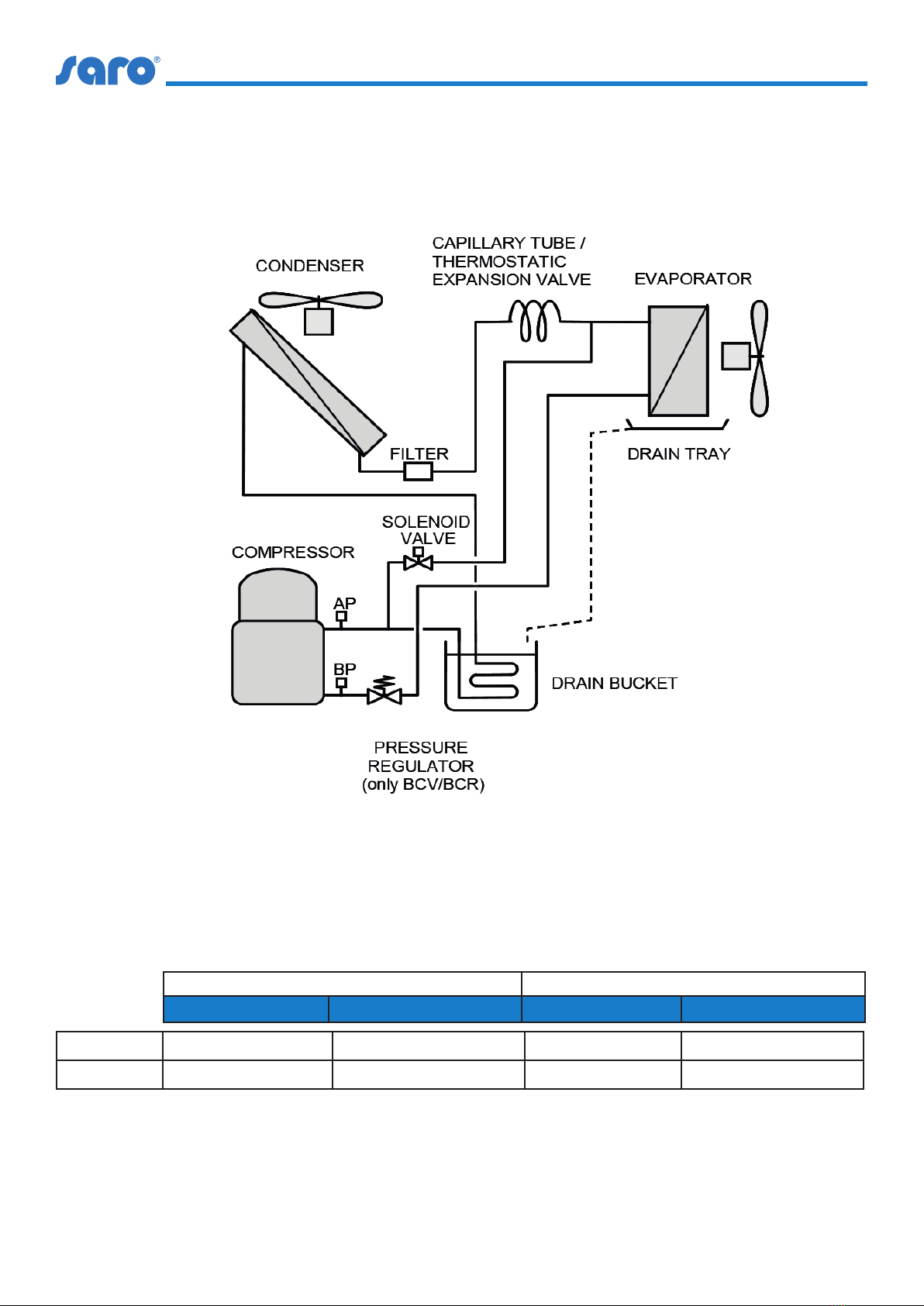
Refrigeration cycle
The refrigeration cycle uses a phase change refrigerant uid
in a closed circuit, with the following four
steps:
Expansion: refrigerant expansion takes place in the capillary
tube between high and low pressure sections. During the
expansion, liquid refrigerant cools down to the evaporating
temperature.
Evaporation: In the evaporator the refrigerant evaporates
under constant temperature and pressure absorbing
heat from the cold room. Once the refrigerant vapour has
been fully evaporated, it is slightly overheated beyond the
evaporation temperature.
Compression: The resultant refrigerant vapour is suctioned
from the evaporator by the compressor through the suction
line. The compressor compresses the refrigerant vapour up to
high pressure and temperature.
Condensation: the hot high pressure gas is desuperheated
and condensed, at a constant pressure
and temperature, in the el condenser by exhausting the latent
evaporation to the outer ambient. Once
the refrigerant has been fully condensed, the liquid
refrigerant is overcooled beyond the condensing
temperature.
High pressure liquid refrigerant is then driven to the capillary
tube, and therefore closing the circuit.
Defrost cycle
Because of the evaporator temperature can be below 0ºC
(32ºF), frost is likely to deposit on the vaporator surface
through the condensation of the water vapour contained in
the air. To prevent the air ow from being obstructed with the
consequently loss of performance, the instrument switches
automatically to the defrost operation mode every given
period of time.
During the defrost cycle, by opening the solenoid valve, part
of the hot gas from the compressor discharge is injected
into the evaporator. The evaporator temperature is rapidly
increased in order to melt the frost on it while the inside fan
is o.
The defrost water is collected in the drain tray and conducted
to the drain bucket. This drain bucket contains a hot gas
coil to progressively evaporate the drain water to the outer
ambient.
INTARBLOCK und INTARTOP sind Kältemaschinen, die unter
Dampfverdichtung arbeiten.
Kältekreislauf
Der Kältekreislauf verwendet ein Phasenwechsel-Kältemittel
in einem geschlossenen Kreislauf mit den folgenden vier
Schritten:
Expansion: Die Kältemittelausdehnung ndet im Kapillarrohr
zwischen Hoch- und Niederdruck statt.
Sektionen. Während der Expansion kühlt üssiges Kältemittel
auf die Verdampfungstemperatur ab.
Verdampfung: Im Verdampfer verdampft das Kältemittel
unter konstanter Temperatur und Druck, wobei die
Wärme aus dem Kühlraum absorbiert wird. Nachdem der
Kältemitteldampf vollständig verdampft ist, wird er über die
Verdampfungstemperatur hinaus leicht überhitzt.
Verdichtung: Der entstehende Kältemitteldampf wird vom
Verdampfer durch den Verdichter über die Saugleitung aus
dem Verdampfer angesaugt. Der Kompressor verdichtet den
Kältemitteldampf unter hohen Druck und Temperatur.
Kondensation: Das heiße Hochdruckgas wird bei konstantem
Druck destilliert und kondensiert.
und Temperatur, im el-Kondensator durch Absaugen der
latenten Verdampfung in die äußere Umgebung. Einmal
Das Kältemittel wurde vollständig kondensiert, das üssige
Kältemittel wird über die Kondensation hinaus überkühlt.
Temperatur.
Das üssige Hochdruck-Kältemittel wird dann zum
Kapillarrohr geleitet und schließt den Kreislauf.
Abtauzyklus
Da die Temperatur des Verdampfers unter 0ºC (32ºF) liegen
kann, ist es wahrscheinlich, dass sich durch die Kondensation
des in der Luft enthaltenen Wasserdampfs Frost auf der
Verdampferoberäche ablagert. Um zu verhindern, dass der
Luftstrom mit dem daraus resultierenden Leistungsverlust
behindert wird, schaltet das Gerät automatisch nach jeder
Zeit in den Abtaubetrieb.
Während des Abtauzyklus wird durch Önen des
Magnetventils ein Teil des Heißgases aus dem
Verdichteraustritt in den Verdampfer eingespritzt. Die
Verdampfertemperatur wird schnell erhöht, um den Frost
auf dem Verdampfer zu schmelzen, während der Innenlüfter
ausgeschaltet ist.
Das Tauwasser wird in der Auangwanne gesammelt und in
den Auangbehälter geleitet. Dieser Abusskübel enthält
eine Heißgasschlange, um das Abusswasser nach und nach
an die äußere Umgebung verdampfen zu lassen.

Stand 03/2018 TM
6
EINSATZGRENZEN / OPERATION LIMITS
SCHEMATISCHE DARSTELLUNG / SCHEMATIC DIAGRAM
KAPILLARROHR / KAPILLARROHR
THERMOSTATIC EXPANSIONSVENTIL
Kondensator Verdampfer
Verdampfer
Abusskübel
Filter
Kompressor
Elektromagnetventil
Druckregulierung
(nur BCV/BCR)
INTARBLOCK und INTARTOP sind für den Dauerbetrieb in
folgenden Bereichen ausgelegt Temperaturbegrenzungen:
INTARBLOCK and INTARTOP units are designed for continuous
operation within the following temperature limits:
Kühlraumtemperatur / Cold Room Temperature Umgebungstemperatur / Ambient Temperature
Max Min Max Min
MCV +10 °C (50 °F) -5 °C (23 °F) +45 °C (113 °F) +15 °C (59 °F)
BCV -15 °C (50 °F) -25 °C (-13 °F) +45 °C (113 °F) +15 °C (59 °F)
Das Gerät sollte über diese Grenzen hinaus nur für kurze
Zeiträume oder während der Inbetriebnahme arbeiten.
The unit should work beyond these limits only for short
periods of time or during the start-up.

7
Stand 03/20187 TM
ZUSAMMENSETZUNG / COMPOSITION
Die MCV-Geräte sind in geschlossener Bauweise aufgebaut.
Die Komponenten werden auf einer Stahlkonstruktion
montiert und mit einem vorlackierten, verzinkten Stahlmantel
abgedeckt. Es besteht aus:
MCV units are built on a self-contained construction. The
components are assembled on a steel structure and covered
with a prelacquered galvanised steel shell. It consists of:
Refrigerant circuit
• Hermetic reciprocating compressor with internal
protection, assembled on silentblocs
• HP and LP pressure switches.
• HP and LP load nipples.
• Thermostatic expansion valve (capillary tube in models
MCV and MCR from 0008 to 2026).
• Pressure regulator (only for BCV and BCR models).
• Antiacid dehydrating lter.
• Evaporation coil in copper tubes and aluminium ns with
stainless steel drain tray.
• Condensation coil in copper tubes and aluminium ns.
• Solenoid valve for the hot gas bypass.
• Water drain bucket including hot gas coil for the
automatic evaporation of drain water.
Kältemittelkreislauf
• Hermetischer Kolbenkompressor mit internem Schutz,
montiert auf Silentblöcken R404-A Kältemittelbelastung
• HP- und LP-Druckschalter..
• HP- und LP-Lastnippel.
• Thermostatisches Expansionsventil (Kapillarrohr bei den
Modellen MCV und MCR von 0008 bis 2026).
• Druckregler (nur für BCV- und BCR-Modelle).
• Entwässerungslter gegen Säuren.
• Verdampferschlange in Kupferrohren und
Aluminiumlamellen mit Auangwanne aus Edelstahl.
• Kondensationswärmetauscher in Kupferrohren und
Aluminiumlamellen.
• Magnetventil für den Heißgasbypass.
• Wasserablaufschaufel mit Heißgasschlange für die
automatische Verdampfung von Abusswasser.
Elektrische Schalttafel
• Leistungsschalter-Schutz
• Elektrische Steuerung XW270K mit den folgenden
Elementen und Eigenschaften:
- Transformator 230 VAC / 12 VCC, Mikroprozessor,
- Alarmrelais, Verdichterrelais, Abtaurelais,
- Relais für Verdampfergebläse, Kühlraum-Lichtrelais,
- Relais für Verüssigergebläse, Türschalter
Digitaleingang
- H/LP Druckschaltereingang, Innentemperatur NTC-
Fühler
- Außentemperatur NTC-Fühler, Abtauung Fühler NTC
- RS485-Anschluss, Anschluss des Programmierschlüssels,
- V820 Tastatur
Electric board
• Circuit breaker protection
• Electric control XW270K with the following elements and
features:
- transformer 230 VAC / 12 VCC, microprocessor,
- alarm relay, compressor relay, defrost relay,
- evaporator fan relay, cold room light relay,
- condenser fan relay, door switch digital input,
- H/LP pressure switch input, inside temperature NTC
probe
- outside temperature NTC probe, defrost NTC probe
- RS485 connection, programming key connection
- V820 keyboard
Luftkreisläufe
NF-Version:
• Direkt angetriebene Axialventilatoren mit
Einphasenmotor. Dynamisch ausbalancierte Lamellen
mit Schutzgitter.
Air circuits
NF-version:
• Direct driven axial fans with single phase motor.
Dynamically equilibrated blades with protection
• grill.
CF-Version:
• Direkt angetriebene Radialventilatoren mit
Einphasenmotor. Dynamisch ausbalancierter Rotor.
CF-version:
• Direct driven centrifugal fans with single phase motor.
Dynamically equilibrated rotor.

Stand 03/2018 TM
8
Elektrische Schalttafel
• Kompressor-Dauerkondensator in einphasigen Anlagen.
• Verdichter-Startrelais und Verüssiger in einphasigen
Einheiten.
• Erdungsanschluss für Kompressor und Motorlüfter.
• Kühlraumbeleuchtung.
• Anschluss des Türmikroschalters.
• Tür-Mikroschalter (optional).
• Türheizkabel (nur für BCV- und BCR-Modelle).
• Kurbelwannenheizung (als Option).
• Entwässerungsrohr-Heizkabel (nur für BCV- und BCR-
Modelle).
Electric board
• Compressor permanent condenser in single phase units.
• Compressor start relay and condenser in single phase
units.
• Ground connection for compressor and motorfans.
• Cold room light.
• Door microswitch connection.
• Door microswitch (as an option).
• Door heating cable (only for BCV and BCR models).
• Crankcase heater (as an option).
• Draining pipe heating cable (only for BCV y BCR models).
TESTS / TESTS
SICHERHEITSVORRICHTUNGEN / SAFETY DEVICES
Alle INTARBLOCK-Geräte wurden zuvor im Werk nach
folgendem Prüfprotokoll geprüft und getestet:
• Helium-Dichtheitsprüfung. Auf Wunsch erhalten Sie ein
auslaufsicheres Zertikat.
• Kältemittelbelastung.
• Funktionsprüfung für Kühl- und Abtaubetrieb unter
Nennbetriebsbedingungen.
• Prüfung der Sicherheitseinrichtungen.
INTARBLOCK Geräte verfügen über folgende
Sicherheitseinrichtungen:
• HP- und LP-Druckendschalter zum Schutz des Gerätes vor
ungewöhnlichen Druckverhältnissen.
• Thermoschalter mit automatischem Wiederanlauf im
Verdichter und in den Ventilatoren zum Schutz der
Motorverdrahtung gegen Überlastungen.
• Leistungsschalter-Schutz.
• Gemeinsamer Masseanschluß
INTARBLOCK units feature the following safety devices:
• HP and LP pressure limit switches to protect the unit
against unusual pressure levels.
• Thermal switches with automatic restart in compressor
and fans to protect motor wirings from overloads.
• Circuit breaker protection.
• Common ground connection.
Every INTARBLOCK units have been previously checked and
tested in factory according to the following test protocol:
• Helium leak-proof test. A leak-proof certicate is supplied
upon request.
• Refrigerant load.
• Operation test for refrigeration and defrost modes under
nominal operating conditions.
• Safety devices checking.

9
Stand 03/20187 TM
AGGREGATE NEGATIV ODER POSITIV: GEEIGNET FÜR FOLGENDE CRKÜHLZELLEN MIT BODEN
NEGATIVE OR POSITIVE AGGREGATES: SUITABLE FOR THE FOLLOWING CR COLD ROOMS WITH FLOOR
Kühlaggregat (positiv)
Cooling unit (positive) 447-2000 447-2005 447-2010
Tiefkühlaggregat (negativ)
Freezing unit (negative) 447-2020 447-2025 447-2030
Modellname der passenden
Kühlzelle
Model name of the suitable
refrigeration unit
CR 1 CR 6 CR 10 CR 1 CR 3 CR 10
Bestell-Nr.:
Order No.: 447-1000 447-1025 447-1045 447-1000 447-1010 447-1045
Volumen
Capacity 1,95 m³ 5,20 m³ 8,12 m³ 1,95 m³ 3,90 m³ 8,12 m³
Nutzäche:
Useful area: 0,96 m² 2,56 m² 4,00 m² 0,96 m² 1,92 m² 4,00 m²
Innenmaß: B/T/H cm
Inside dimension: W/D/H cm 120 x 80 x
203 160 x 160 x
203 200 x 200 x
203 120 x 80 x
203 120 x 160 x
203 200 x 200 x
203
Außenmaß: B/T/H cm
Outside dimension: W/D/H cm 137 x 97 x
220 177 x 177 x
220 217 x 217 x
220 137 x 217 x
220 137 x 177 x
220 217 x 217 x
220
Modellname der passenden
Kühlzelle
Model name of the suitable
refrigeration unit
CR 2 CR 7 CR 11 CR 2 CR 5 CR 11
Bestell-Nr.:
Order No.: 447-1005 447-1030 447-1050 447-1005 447-1020 447-1050
Volumen
Capacity 2,93 m³ 6,50 m³ 7,80 m³ 2,93 m³ 3,90 m³ 3,84 m³
Nutzäche:
Useful area: 1,44 m² 3,20 m² 3,84 m² 1,44 m² 1,92 m² 3,84 m²
Innenmaß: B/T/H cm
Inside dimension: W/D/H cm 120 x 120 x
203 160 x 200 x
203 240 x 160 x
203 120 x 120 x
203 160 x 120 x
203 240 x 160 x
203
Außenmaß: B/T/H cm
Outside dimension: W/D/H cm 137 x 137 x
220 177 x 217 x
203 257 x 177 x
220 137 x 137 x
220 177 x 137 x
220 257 x 177 x
220
Modellname der passenden
Kühlzelle
Model name of the suitable
refrigeration unit
CR 3 CR 8 CR 12 CR 4 CR 6 CR 12
Bestell-Nr.:
Order No.: 447-1010 447-1035 447-1055 447-1015 447-1025 447-1055
Volumen
Capacity 3,90 m³ 4,88 m³ 9,75 m³ 2,60 m³ 5,20 m³ 9,75 m³
Nutzäche:
Useful area: 1,92 m² 2,40 m² 4,80 m² 1,28 m² 2,56 m² 4,80 m²
Innenmaß: B/T/H cm
Inside dimension: W/D/H cm 120 x 160 x
203 200 x 160 x
203 240 x 200 x
203 160 x 80 x
203 160 x 160 x
203 240 x 200 x
203
Außenmaß: B/T/H cm
Outside dimension: W/D/H cm 137 x 177 x
220 217 x 137 x
220 257 x 137 x
220 177 x 97 x
220 177 x 177 x
220 257 x 217 x
220

Stand 03/2018 TM
10
AGGREGATE NEGATIV ODER POSITIV: GEEIGNET FÜR FOLGENDE CRKÜHLZELLEN MIT BODEN
NEGATIVE OR POSITIVE AGGREGATES: SUITABLE FOR THE FOLLOWING CR COLD ROOMS WITH FLOOR
Kühlaggregat (positiv)
Cooling unit (positive) 447-2000 447-2005 447-2010
Tiefkühlaggregat (negativ)
Freezing unit (negative) 447-2020 447-2025 447-2030
Modellname der passenden
Kühlzelle
Model name of the suitable
refrigeration unit
CR 4 CR 9 CR 7
Bestell-Nr.:
Order No.: 447-1015 447-1040 447-1030
Volumen
Capacity 2,60 m³ 6,50 m³ 6,50 m³
Nutzäche:
Useful area: 1,92 m² 3,20 m² 3,20 m²
Innenmaß: B/T/H cm
Inside dimension: W/D/H cm 160 x 80 x
203 200 x 160 x
203 160 x 200 x
203
Außenmaß: B/T/H cm
Outside dimension: W/D/H cm 177 x 97 x
220 217 x 177 x
220 177 x 217 x
220
Modellname der passenden
Kühlzelle
Model name of the suitable
refrigeration unit
CR 5 CR 8
Bestell-Nr.:
Order No.: 447-1020 447-1020
Volumen
Capacity 3,90 m³ 4,88 m³
Nutzäche:
Useful area: 1,92 m² 2,40 m²
Innenmaß: B/T/H cm
Inside dimension: W/D/H cm 160 x 120 x
203 200 x 120 x
203
Außenmaß: B/T/H cm
Outside dimension: W/D/H cm 177 x 137 x
220 217 x 137 x
220
Modellname der passenden
Kühlzelle
Model name of the suitable
refrigeration unit
CR 9
Bestell-Nr.:
Order No.: 447-1040
Volumen
Capacity 6,50 m³
Nutzäche:
Useful area: 3,20 m²
Innenmaß: B/T/H cm
Inside dimension: W/D/H cm 200 x 160 x
203
Außenmaß: B/T/H cm
Outside dimension: W/D/H cm 217 x 177 x
220

11
Stand 03/20187 TM
MCVSERIE TECHNISCHE BESCHREIBUNG / MCV SERIES TECHNICAL FEATURES
MCV-Serie 447-2000
0010
447-2005
0012
447-2010
0014
Kühlleistung
Cooling capacity
Kühlleistung (1) (W)
Cooling capacity (1) (W) 728 808 1077
Aufgenommene Energie (2) (W)
Absorbed power (2) (W) 570 640 804
COP-Leistung
COP performance 1,28 1,27 1,34
Installierte Leistung (3) (kW)
Installed power (3) (kW) 0,73 0,86 0,98
Kondensatorgebläse
NF-Ausführung
Condenser fan
NF version
Nennluftvolumenstrom (m3/h)
Nominal air ow rate (m3/h) 375 575
Typ
type Axial
Axial
Leistung (W) - U/min.
Power (W) - r.p.m 85 W @ 1300
Verdampfergebläse
Evaporator fan
Nennluftvolumenstrom (m3/h)
Nominal air ow rate (m3/h) 300 550
Reichweite (m)
Range (m) 3 4
Typ
Type Axial
Axial
Leistung (W) - U/min.
Power (W) - r.p.m 47 W @ 2500 462 W @ 2600
Kompressor
Compressor
Typ
Type Hermetic reciprocating
Hermetisch auf- und abgehend
Hubraum (m3/h)
Swept volume (m3/h) 1,54 1,79 2,32
Nennauslassdruck
(bar rel.)
Nominal discharge pressure
(bar rel.)
20
Nennsaugdruck (bar)
rel.)
Nominal suction pressure (bar
rel.)
3,40
Nennleistung (CV)
Nominal power (CV) 3/8 1/2 1/2
Hochdruckschalter
High pressure switch
Typ
Type ACB
Marke
Brand Danfoss
Model
Model 061F6052
Ausschnitt (bar rel.)
Cut out (bar rel.) 28
1) Kühlleistung bei einer Kühlraumtemperatur von 0 ºC (32 ºF) und einer Umgebungstemperatur von 35 ºC (95 ºF).
1) Cooling capacity under cold room temperature of 0 ºC (32 ºF) and ambient temperature of 35 ºC (95 ºF).
(2) Gesamte aufgenommene Leistung von Verdichter und Ventilatoren unter Nennbedingungen (axiale Ausführung).
(2) Total absorbed power by compressor and fans under nominal condition (axial version).
(3) Gemäß Denition in RD138/2011. IF-01.
(3) As dened by RD138/2011. IF-01.

Stand 03/2018 TM
12
MCVSERIE TECHNISCHE BESCHREIBUNG / MCV SERIES TECHNICAL FEATURES
(4) Maximale Stromaufnahme auch außerhalb der Betriebsgrenzen des Verdichters (axiale Ausführung).
(4) Maximum absorbed current even beyond compressor operation limits (axial version).
MCV-Serie 447-2000
0010
447-2005
0012
447-2010
0014
Max. absorbierte
Intensität (A)(4)
Max. absorbed intensity
(A)(4)
230 V / ph / 50 Hz 5,9 6,7 6,7
400 V / ph / 50 Hz Nicht erhältlich
not available
Anlauntensität (A)
Starting-up intensity (A)
230 V / ph / 50 Hz 18,8 20,2 20,9
400 V / ph / 50 Hz Nicht erhältlich
not available
Kältemittel
Refrigerant
Typ
Type R-404A / Grupo L1 / PCA-100: 3260
Belastung (kg)
Load (kg) 0,50 0,56 0,70
CO²-Äquivalent
CO²-equivalent Tonnen (t)
tons (t) 1,961 2,196 2,745
Abmessungen
Dimensions
Länge (mm)
Length (mm) 556 556 854
Breite (mm)
Wide (mm) 420 420 400
Höhe (mm)
Height (mm) 683 683 880
Gewicht
Weight (kg) 37 38 60

13
Stand 03/20187 TM
BCVSERIE TECHNISCHE BESCHREIBUNG / BCV SERIES TECHNICAL FEATURES
BCV-Serie 447-2020
0018
447-2025
1024
447-2030
1034
Kühlleistung
Cooling capacity
Kühlleistung (1) (W)
Cooling capacity (1) (W) 479 720 866
Aufgenommene Energie (2) (W)
Absorbed power (2) (W) 620 914 1136
COP-Leistung
COP performance 0,77 0,79 0,76
Installierte Leistung (3) (kW)
Installed power (3) (kW) 0,87 1,29 1,76
Kondensatorgebläse
NF-Ausführung
Condenser fan
NF version
Nennluftvolumenstrom (m3/h)
Nominal air ow rate (m3/h) 375 575 575
Typ
type Axial
Axial
Leistung (W) - U/min.
Power (W) - r.p.m 85 W @ 1300 85 W @ 1300 85 W @ 1300
Verdampfergebläse
Evaporator fan
Nennluftvolumenstrom (m3/h)
Nominal air ow rate (m3/h) 300 550 550
Reichweite (m)
Range (m) 3 4 4
Typ
Type Axial
Axial
Leistung (W) - U/min.
Power (W) - r.p.m 47W @ 2500 62 W @ 2600 62 W @ 2600
Kompressor
Compressor
Typ
Type Hermetic reciprocating
Hermetisch auf- und abgehend
Hubraum (m3/h)
Swept volume (m3/h) 3,18 4,57 6,01
Nennauslassdruck
(bar rel.)
Nominal discharge pressure
(bar rel.)
20
Nennsaugdruck (bar)
rel.)
Nominal suction pressure (bar
rel.)
1,30
Nennleistung (CV)
Nominal power (CV) 5/8 3/4 1 1/4
Hochdruckschalter
High pressure switch
Typ
Type ACB
Marke
Brand Danfoss
Model
Model 061F6052
Ausschnitt (bar rel.)
Cut out (bar rel.) 28
1) Kühlleistung bei einer Kühlraumtemperatur von 0 ºC (32 ºF) und einer Umgebungstemperatur von 35 ºC (95 ºF).
1) Cooling capacity under cold room temperature of 0 ºC (32 ºF) and ambient temperature of 35 ºC (95 ºF).
(2) Gesamte aufgenommene Leistung von Verdichter und Ventilatoren unter Nennbedingungen (axiale Ausführung).
(2) Total absorbed power by compressor and fans under nominal condition (axial version).
(3) Gemäß Denition in RD138/2011. IF-01.
(3) As dened by RD138/2011. IF-01.

Stand 03/2018 TM
14
BCVSERIE TECHNISCHE BESCHREIBUNG / BCV SERIES TECHNICAL FEATURES
BCV-Serie 447-2020
0018
447-2025
1024
447-2030
1034
Max. absorbierte
Intensität (A)(4)
Max. absorbed intensity
(A)(4)
230 V / ph / 50 Hz 4,8 8,4 10,9
400 V / ph / 50 Hz Nicht verfügbar
No disponible
Anlauntensität (A)
Starting-up intensity (A)
230 V / ph / 50 Hz 21,9 29,9 40,9
400 V / ph / 50 Hz Nicht verfügbar
No disponible
Kältemittel
Refrigerant
Typ
Type R-404A / Grupo L1 / PCA-100: 3260
Belastung (kg)
Load (kg) 0,60 0,70 0,60
CO²-Äquivalent
CO²-equivalent Tonnen (t)
tons (t) 2,353 2,745 2,353
Abmessungen
Dimensions
Länge (mm)
Length (mm) 556 854 854
Breite (mm)
Wide (mm) 420 400 400
Höhe (mm)
Height (mm) 683 880 880
Gewicht
Weight (kg) 38 60 60
(4) Maximale Stromaufnahme auch außerhalb der Betriebsgrenzen des Verdichters (axiale Ausführung).
(4) Maximum absorbed current even beyond compressor operation limits (axial version).

15
Stand 03/20187 TM
KÜHLLEISTUNG / COOLING CAPACITY
MCV-Serie / MCV series BCV-Serie / BCV series
Kapazität
(W)
Capacity
(W)
Kühlraumtemperatur
Cold room temperature
- 5 °C 0 °C + 5 °C + 10 °C
MCV Serie
MCV series
Kühlleistung
(W)
Cooling
capacity
(W)
Aufgenommene
Leistung (W)
Absorbed power
(W)
Kühlleistung
(W)
Cooling
capacity
(W)
Aufgenommene
Leistung (W)
Absorbed power
(W)
Kühlleistung
(W)
Cooling
capacity
(W)
Aufgenommene
Leistung (W)
Absorbed power
(W)
Kühlleistung
(W)
Cooling
capacity
(W)
Aufgenommene
Leistung (W)
Absorbed power
(W)
447-2000
0010 604 533 728 570 871 624 1012 666
447-2005
0012 568 619 808 676 961 706 1118 759
447-2010
1014 893 756 1077 804 1270 858 1485 920
Umgebungstemperatur: 35 °C
Ambiente Temp: 35 °C
Leistung (W)
Potencia (W)
Kühlraumtemperatur
Cold room temperature
- 25 °C - 20 °C - 15 °C
MCV Serie
MCV series
Kühlleistung
(W)
Cooling
capacity
(W)
Aufgenommene Leistung
(W)
Absorbed power (W)
Kühlleistung
(W)
Cooling
capacity
(W)
Aufgenommene Leistung
(W)
Absorbed power (W)
Kühlleistung
(W)
Cooling
capacity
(W)
Aufgenommene Leistung
(W)
Absorbed power (W)
447-2020
0018 379 565 479 620 591 694
447-2025
1024 548 619 808 676 961 706
447-2030
1034 668 756 1077 804 1270 858
Umgebungstemperatur: 35 °C
Ambiente Temp: 35 °C

Stand 03/2018 TM
16
ABMESSUNG / DIMENSIONS
CV-NF Models
Abmessung (mm)
Dimensions (mm) A B C D E F G H I J K L M
Serie 0
series 0 306 510 383 420 250 50 405 515 n/a
Serie 1
series 1 340 330 880 400 514 122 380 335 75 41 295 13 233
STECKRAHMEN FALLRAHMEN
*Jede Koordinate wird in mm angegeben.
*Every coordinate is given in mm.

17
Stand 03/20187 TM
ELEKTRISCHE ANSCHLÜSSE / ELECTRICAL CONNECTIONS
MCV 447-2000
0010 447-2005
0012 447-2010
1014
Stromversorgung
220-I-50
Power supply
220-I-50
2 x 1,5 mm² + T
Stromversorgung
400-I-50
Power supply
400-I-50
n/a
Kühlraumbeleuchtung
Cold room light 2 x 1 mm² + T
Tür Mikroschalter
Door microswitch 2 x 1 mm²
Fernbedienung
Remote controller 2 x 1 mm²
BCV 447-2020
0018 447-2025
1024 447-2030
1034
Stromversorgung
220-I-50
Power supply
220-I-50
2 x 1,5 mm² + T
Stromversorgung
400-I-50
Power supply
400-I-50
n/a
Kühlraumbeleuchtung
Cold room light 2 x 1 mm² + T
Tür Mikroschalter
Door microswitch 2 x 1 mm²
Fernbedienung
Remote controller 2 x 1 mm²
Bevor Sie das Gerät an das Stromnetz anschließen, vergewissern
Sie sich, dass die Schalttafel in gutem Zustand ist, und befolgen
Sie die folgenden Empfehlungen:
• Beachten Sie das vom Hersteller mitgelieferte Elektroschema.
• Verwenden Sie nur elektrische Kabel mit den entsprechenden
Eigenschaften und Kapazitäten, die den folgenden
Anforderungen in der Tabelle entsprechen. Beachten Sie, dass
einphasige Geräte eine Dreileiterversorgung und dreiphasige
Geräte eine Füneiterversorgung haben, wobei es sich immer
um die Erdungsleitung in grün-gelber Farbe handelt.
• Always install the appropriate protection device on the
supply line. In case that more than one unit is installed,
always provide separate protection devices for each of
the installed units.
• Electrical wires section in power supply wiring is to be
calculated according to the electrical data provided
by manufacturer in data plate, power supply wires
length, wires type, etc.; always according to electrical
regalement.
• Optionally install a door switch on the end of the
supplied cable or close the end of the cable.
• Install the room light in the supplied cable.
• Installieren Sie immer die entsprechende
Schutzeinrichtung an der Zuleitung. Falls mehr als eine
Einheit installiert ist, sollten Sie für jede der installierten
Einheiten separate Schutzvorrichtungen vorsehen.
• Der Querschnitt der elektrischen Leitungen in der
Stromversorgungsleitung ist nach den elektrischen Daten
zu berechnen, die vom Hersteller auf dem Typenschild,
der Länge der Stromversorgungsleitungen, der Art
der Leitungen usw. angegeben sind; immer nach der
elektrischen Zulassung.
• Optional können Sie einen Türschalter am Ende des
mitgelieferten Kabels anbringen oder das Kabelende
schließen.
• Installieren Sie das Raumlicht in dem mitgelieferten Kabel.
Before connecting the unit to the electrical supply, make
sure that the electrical board is in good conditions and
please follow the following recommendations:
• Consult the electrical schema supplied by
manufacturer.
• Only use electrical cables of the appropriate
characteristics and capacity according to the
following table. Notice that single phase units have
a three-wire supply and three phase units have a
vewire supply, being always the ground wire in
green-yellow colour.

18
Stand 03/2018 TM
NOTFALLSYSTEM / EMERGENCY SYSTEM
SCHALLDRUCKPEGEL / SOUND PRESSURE LEVEL
TRANSPORT / TRANSPORT
Die elektronische Regelung der Geräte beinhaltet
Kontrollroutinen und Notfallalarme für folgende Bereiche:
• Sondenausfall.
• Zu hohe und/oder zu niedrige Raumtemperatur.
• Zu hoher oder zu niedriger Kältemitteldruck.
• Zu hohe Umgebungstemperatur.
• Ausfall der elektronischen Steuerung.
• Oene Tür.
The electronic regulation of the units involves control
routines and emergency alarms for the following causes:
• Probe failure.
• Too high and too low room temperature.
• Too high or too low refrigerant pressure.
• Too high ambient temperature.
• Electronic control failure.
• Opened door.
• Always handle the unit in vertical position.
• Never pile up the units during transport.
• Never pile up the units during storage.
• Use a forklift or a pallet jack to handle the unit.
• Keep the unit on its pallet until its nal destination.
• Das Gerät immer in vertikaler Position handhaben.
• Die Geräte niemals während des Transports stapeln.
• Stapeln Sie die Geräte niemals während der Lagerung auf.
• Verwenden Sie einen Gabelstapler oder einen Hubwagen,
um das Gerät zu handhaben.
• Halten Sie das Gerät bis zum endgültigen Bestimmungsort
auf der Palette.
Nach einer Störung wird ein externer Alarm ausgelöst und
das Gerät geht in den Notbetrieb über. Once a failure an external alarm is activated, and the unit
turns into emergency operation mode.
Der Schalldruckpegel ist nach der Installation des Gerätes zu
beachten. Um dies zu erreichen, sollten die Umgebung, die
Art des Gebäudes und der Rest der festen Elemente bei der
Schallübertragung berücksichtigt werden.
Es wird empfohlen, bei Bedarf eine Expertenstudie zu
erstellen.
INTARBLOCK- und INTARTOP-Einheiten sind mit
geräuscharmen Komponenten ausgestattet. Die folgende
Tabelle zeigt Schalldruckpegel, die in 10 m Entfernung
von der Quelle in Freifeldverteilung berechnet wurden
(Richtwirkung = 1):
Behandeln Sie das Gerät vorsichtig, um Beschädigungen
während des Transports zu vermeiden. Bitte befolgen Sie die
folgenden Anweisungen:
Sound pressure level should be observed once the unit is
installed. To do so, the environment, the type of building and
the rest of the solid elements should be considered on the
noise transmission.
It is recommended to deploy an expert study if necesary.
INTARBLOCK and INTARTOP units include low noise
components. The following chart indicates sound pressure
levels calculated at 10 m from the source in open eld
distribution (directivity = 1):
Handle the unit with care to prevent damages during its
transport. Please follow the following instructions:
MCV 0010 0012 1014 BCV 0018 1024 1034
dB(A) 30 30 32 dB(A) 33 38 40
Verpackungsabmessungen (mm)
Packaging dimensions (mm) L
LB
WH
HGewicht
Weight
CV Serie 0
CV series 0 610 460 823 44 Kg
CV Serie 1
CV series 1 905 440 1065 76Kg
L = Länge, B = Breite, H = Höhe
L = lenght, W = width, H = height
B / W

19
Stand 03/20187 TM
ELEKTRISCHE ANSCHLÜSSE / ELECTRICAL CONNECTIONS
MCV 447-2000
0010 447-2005
0012 447-2010
1014
Stromversorgung
220-I-50
Power supply
220-I-50
2 x 1,5 mm² + T
Stromversorgung
400-I-50
Power supply
400-I-50
n/a
Kühlraumbeleuchtung
Cold room light 2 x 1 mm² + T
Tür Mikroschalter
Door microswitch 2 x 1 mm²
Fernbedienung
Remote controller 2 x 1 mm²
BCV 447-2020
0018 447-2025
1024 447-2030
1034
Stromversorgung
220-I-50
Power supply
220-I-50
2 x 1,5 mm² + T
Stromversorgung
400-I-50
Power supply
400-I-50
n/a
Kühlraumbeleuchtung
Cold room light 2 x 1 mm² + T
Tür Mikroschalter
Door microswitch 2 x 1 mm²
Fernbedienung
Remote controller 2 x 1 mm²
Bevor Sie das Gerät an das Stromnetz anschließen, vergewissern
Sie sich, dass die Schalttafel in gutem Zustand ist, und befolgen
Sie die folgenden Empfehlungen:
• Beachten Sie das vom Hersteller mitgelieferte Elektroschema.
• Verwenden Sie nur elektrische Kabel mit den entsprechenden
Eigenschaften und Kapazitäten, die den folgenden
Anforderungen in der Tabelle entsprechen. Beachten Sie, dass
einphasige Geräte eine Dreileiterversorgung und dreiphasige
Geräte eine Füneiterversorgung haben, wobei es sich immer
um die Erdungsleitung in grün-gelber Farbe handelt.
• Always install the appropriate protection device on the
supply line. In case that more than one unit is installed,
always provide separate protection devices for each of the
installed units.
• Electrical wires section in power supply wiring is to be
calculated according to the electrical data provided by
manufacturer in data plate, power supply wires length,
wires type, etc.; always according to electrical regalement.
• Optionally install a door switch on the end of the supplied
cable or close the end of the cable.
• Install the room light in the supplied cable.
• Installieren Sie immer die entsprechende
Schutzeinrichtung an der Zuleitung. Falls mehr als eine
Einheit installiert ist, sollten Sie für jede der installierten
Einheiten separate Schutzvorrichtungen vorsehen.
• Der Querschnitt der elektrischen Leitungen in der
Stromversorgungsleitung ist nach den elektrischen Daten
zu berechnen, die vom Hersteller auf dem Typenschild,
der Länge der Stromversorgungsleitungen, der Art
der Leitungen usw. angegeben sind; immer nach der
elektrischen Zulassung.
• Optional können Sie einen Türschalter am Ende des
mitgelieferten Kabels anbringen oder das Kabelende
schließen.
• Installieren Sie das Raumlicht in dem mitgelieferten Kabel.
Before connecting the unit to the electrical supply, make
sure that the electrical board is in good conditions and
please follow the following recommendations:
• Consult the electrical schema supplied by
manufacturer.
• Only use electrical cables of the appropriate
characteristics and capacity according to the
following table. Notice that single phase units have
a three-wire supply and three phase units have a
vewire supply, being always the ground wire in
green-yellow colour.

20
Stand 03/2018 TM
DATENSCHILD / DATA PLATE
SICHERHEITSEMPFEHLUNGEN / SAFETY RECOMMENDATIONS
Hersteller-Identikation
Manufacturer identication
Seriennummer
Serial number
Stromversorgung
Power supply
Maximal zulässiger Druck
(Hochdruckbereich)
Maximum allowed pressure
(High pressure sector)
Verdichter-Nennleistung
compressor nominal capicity
Maximale Eingangsleistung
Maximum input power
Kältemitteltyp
Refrigerant type
Zusätzliche
Kältemittelbelastung
Additional refrigerant load
Werkskältemittelbelastung
Factory refrigerant load
Herstellungsjahr
Manufacturing year
Phasennummer / Phase number
Frequenz / Frequency
Gesamtkältemittelbelastung
Total refrigerant load
Maximaler absorbierter Strom
Maximum absorbed current
CO2-Äquivalente Tonnen
CO2 equivalent tons
Blockierter Rotorstrom
Locked rotor current
Abtauleistung
Defrosting capacity
Maximal zulässiger Druck
(Niederdruckbereich)
Maximum allowed pressure
(Low pressure sector)
Gewicht / Weight
Model / Model
Die Inbetriebnahme und Reparatur des Gerätes darf nur von
qualiziertem Fachpersonal durchgeführt werden.
Um das Risiko von Unfällen bei der Installation,
Inbetriebnahme oder Wartung zu minimieren, sind die
nachstehenden Anweisungen zu befolgen.
Die Empfehlungen und Hinweise in den
Herstellerhandbüchern sind unbedingt zu beachten,
Schilder und spezische Anweisungen. Auch die Einhaltung
von Gesetzen und Vorschriften ist zwingend vorgeschrieben.
Kältemittel-Lecks können die Ursache sein für:
• Erstickung durch Sauerstoverdrängung in der
Atmosphäre, narkotische Wirkung oder
Herzrhythmusstörungen.
The start-up of the unit and its reparation must be carried out
by qualied personnel.
To minimise the risk of accidents during the installation,
start up or maintenance tasks, below instructions must be
followed.
It is mandatory to observe the recommendations and
instructions as shown in manufacturer manuals,
plates and specic instructions. It is also mandatory to
observe law and regulations.
Refrigerant leaks may cause:
• Suocation due to oxygen displacement in the
atmosphere, narcotic eect or heart arrhythmia.
WARNUNG!
Bevor Sie das Gerät in Betrieb nehmen, verge-
wissern Sie sich, dass die allgemeine Stromver-
sorgung unterbrochen ist, um Stromschläge zu
vermeiden.
WARNUNG!
Stellen Sie sicher, dass der Arbeitsbereich ausrei-
chend belüftet ist.
Verwenden Sie eine Schutzmaske und ein Paar
Handschuhe. Vermeiden Sie jeglichen Kontakt
zwischen dem Kältemittel und der Haut und
achten Sie auf ein scharfes Ende des Gerätes.
WARNING!
Before operating on the unit, verify that the general supply is
disconnected to avoid electrical shocks.
WARNING!
Ensure that the working area is properly ventilated.
Use a safety mask and a pair of gloves. Avoid any contact
between the refrigerant and the skin and mind any sharp end
of the unit.
This manual suits for next models
5
Table of contents
Other saro Accessories manuals