HRT 25B/…-2500… - 02 2019/04
Technical data
Optical data
Typ. maximum range (white 90%) 1)
1) Typ. max. range/adjustment range: max. achievable range/adjustment range for light objects (white 90%)
50 … 3000mm
Operating range 2)
2) Operating range: recommended range for objects with different diffuse reflection
50 … 2500mm
Adjustment range (teach-in range) 150 … 3000/2500mm (90%/4% diffuse reflection)
Light source 3)
3) Average life expectancy 100,000h at an ambient temperature of 25°C
LED (modulated light)
Wavelength 850nm (infrared light)
Light spot Approx. Ø 60mm at 1m 4)
Approx. Ø 110mm at 2m 4)
4) Field of view of sensor: Ø 40mm at 1m, Ø 70mm at 2m
Error limits
Adjustment accuracy (via IO-Link) ± 10% (300 ... 2500 mm)
Repeatability 5)
5) For measurement range 50 to 2500mm, depending on diffuse reflectance and object distance,
at 20°C after 20min. warmup time, medium range of UB, measurement object 50x50mm²
<±15mm
B/W detection thresh. (2 … 90% rem.) ± 25mm
Temperature drift ± 2mm/K
Time behavior
Switching frequency 30 Hz 6)
6) Depending on diffuse reflectance
Response time < 70ms 6)
Readiness delay 300ms
Electrical data
Operating voltage UB 7)
7) For UL applications: use is permitted exclusively in Class 2 circuits according to NEC
18 … 30VDC (incl. residual ripple)
Residual ripple 15% of UB
Open-circuit current 32mA
Switching output …/L6… Pin 4 (Q1): IO-Link Data, in SIO mode push-pull switching
output
Pin 2 (Q2): Push-pull switching output 8) ,
PNP light switching, NPN dark switching
8) The push-pull switching outputs must not be connected in parallel
Signal voltage high/low (UB-2 V)/2V
Output current Max. 50mA
IO-Link COM2 (38.4kBaud), vers. 1.1, min. cycle time 2.3ms,
SIO is supported
Indicators
Top side of sensor
Green LED Ready
Yellow LED Switching output Q1 active, see tables
Sensor front
Multicolor LED Yellow Switching output Q1 active, see tables
Blue Switching output Q2 active, see tables
White (yellow+blue) Switching output Q1 and Q2 active, see tables
Mechanical data
Housing Plastic (PC-ABS)
Optics cover Plastic (PMMA)
Weight With connector: 15g
With 200mm cable and connector: 30g
With 2m cable: 55g
Connection type Cable 2m (cross section 5x0.20mm²)
Connector M12, 5-pin
Cable 0.2m with connector M12, 5-pin
Environmental data
Ambient temp. (operation/storage) 9)
9) UL certification for a temperature range of -30°C to 60°C
-30°C … +50°C/-40°C … +60°C
Protective circuit 10)
10)1=transient protection, 2=polarity reversal protection, 3=short circuit protection for all outputs
1, 2, 3
VDE protection class III
Degree of protection IP 66, IP 67
Light source Exempt group (in acc. with EN 62471)
Standards applied IEC 60947-5-2
Certifications UL 508, C22.2 No.14-13 7) 9) 11)
11)These proximity switches shall be used with UL Listed Cable assemblies rated 30V, 0.5A min,
in the field installation, or equivalent (categories: CYJV/CYJV7 or PVVA/PVVA7)
Additional functions
Deactivation input
Transmitter inactive/active 8V/2V 12)
12)Upon deactivation, the outputs become inactive
Activation/disable delay 20ms
Input resistance Approx. 10k
Observe intended use!
This product is not a safety sensor and is not intended as personnel protection.
The product may only be put into operation by competent persons.
Only use the product in accordance with its intended use.
Tables
Switching
points1)
1) Applies for object teach
No
reflection
Object
detected
Top side of sensor
Yellow
LED Q1
Off On
Sensor front
Q1<Q2 Q1>Q2
Yellow
LED Q1
Off On On
Blue LED Q2 Off On On
White LED2)
Q1+Q2
2) LED color white = yellow + blue
Off On –
Diagrams
Notes
Adjusting the switching points
•Object teach:
Align sensor with object.
Q1: Press teach button for approx.
2s,
Q2: Press teach button for approx.
7s
Switching point is taught.
Object is detected if the respective
Q1/Q2 indicator illuminates.
•Hysteresis:
To ensure continuous object detec-
tion in the switching point, the sensor
has a switch hysteresis.
Object is no longer detected if:
distance to sensor > teach point +
reserve + hysteresis.
•Factory setting:
Hysteresis: 30 mm (adjustable),
reserve: 30 mm (adjustable)
Application notes
• With the set detection range, a toler-
ance of the upper scanning range
limit is possible depending on the
reflection properties of the material
surface.
• Range/reflectivity:
• Reflective, high-gloss objects (e.g.
mirrors) are not detected.
• Optimum detection behavior is
achieved when the light spot is fully
on the object.
• The maximum possible angle rela-
tive to the object surface depends on
the reflection properties.
• An only partially covered light spot
can affect the detection behavior.
A4 % … 90 % diffuse reflection
Object/
diffuse
reflection
2% 0.05 … 1.7m
90% 0.05 … 3.0m
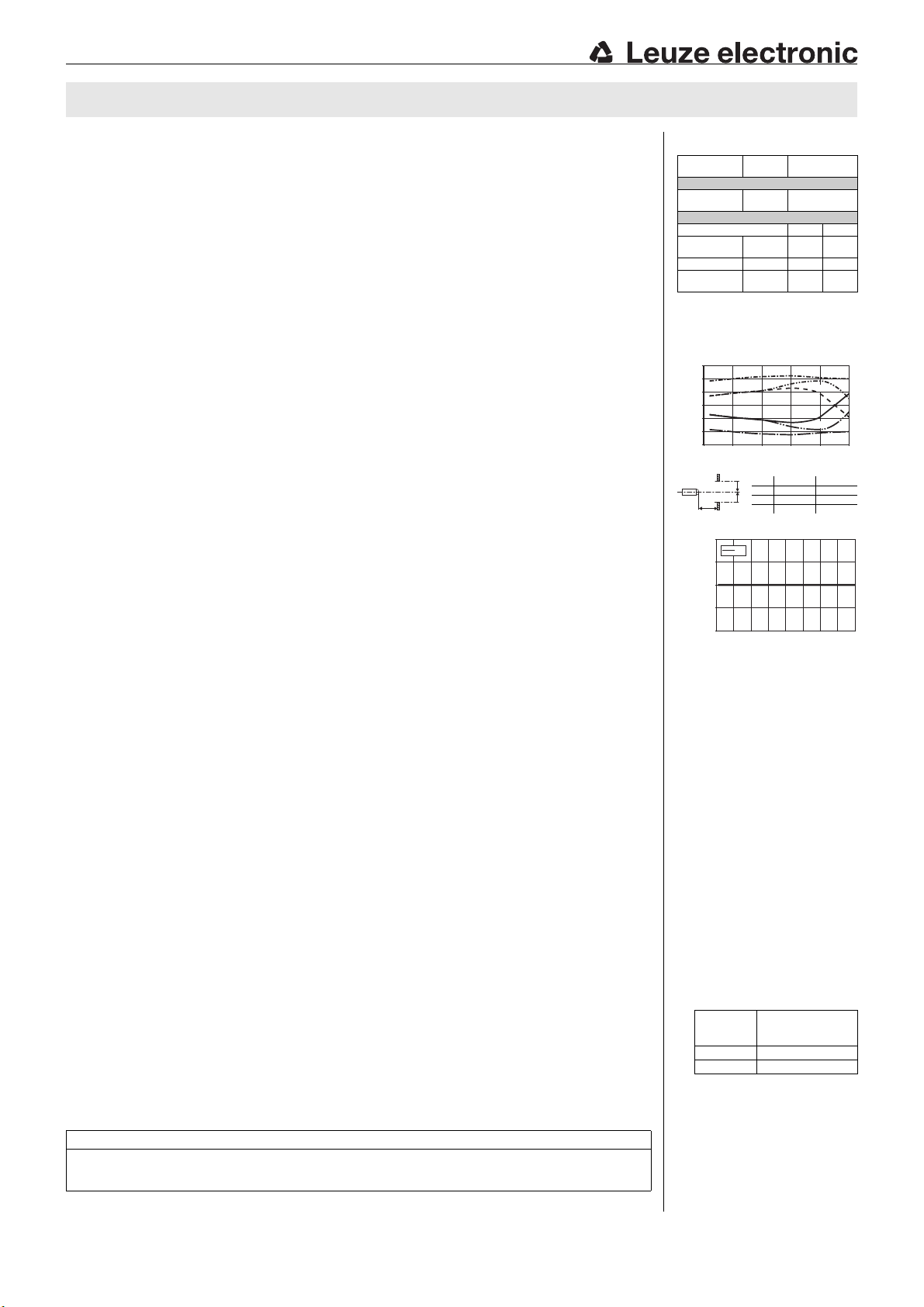
-30
-20
-10
0
10
20
30
0 1000 2000500 1500 2500
y1A
y2A
y1B
y2B
y2C
y1C
Distance x [mm]
Misalignment y [mm]
Typ. response behavior
Object Background
y1/2AWhite White
y1/2BWhite Black
y1/2CBlack Black
25
0
50
75
100
01 2 3 4
A
Range x [m]
Max. range change [mm]
Reference: white 90%
Black/white behavior
HRT 25B Long Range


