4
Contents Warnings and
Safety Precautions
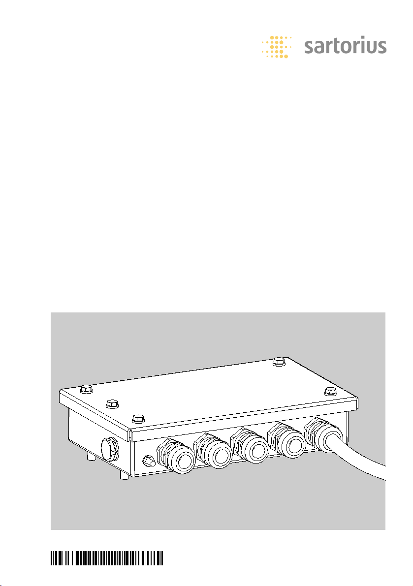
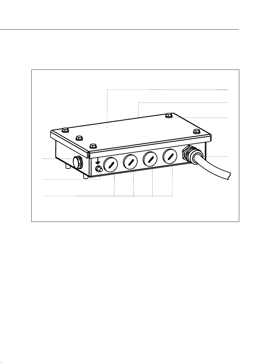
3General View of the Equipment
4Warnings and Safety Precautions
5Intended Use
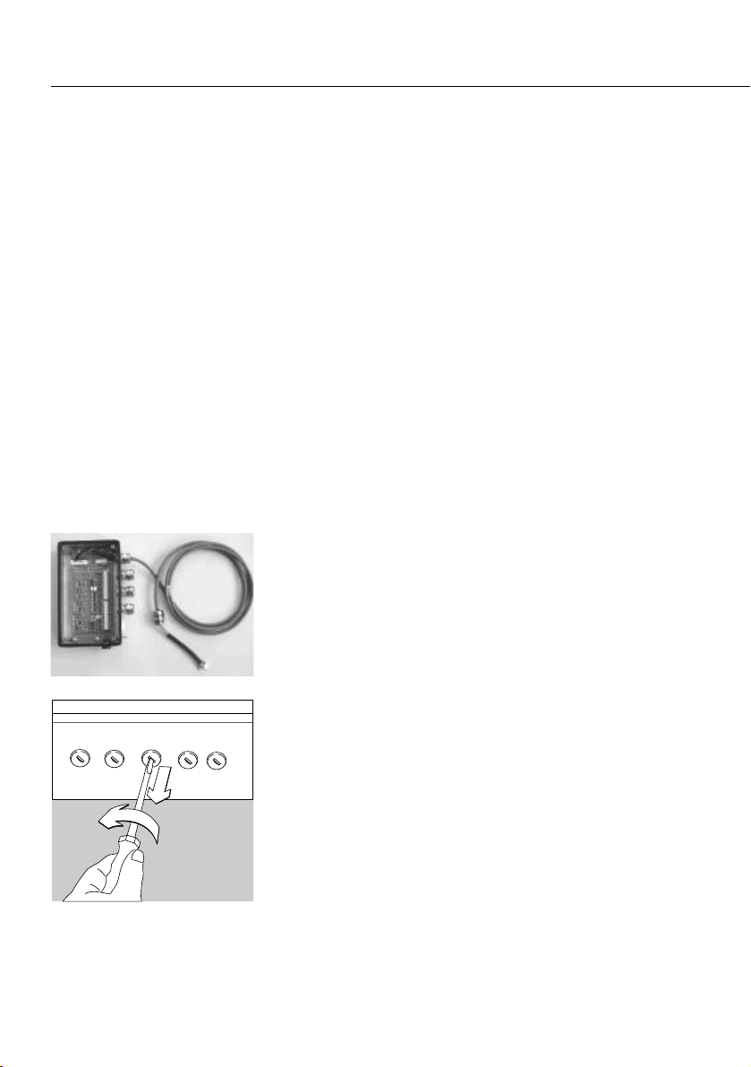
6Installation
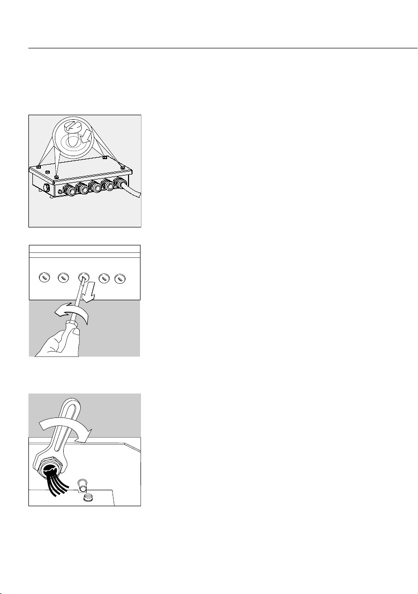
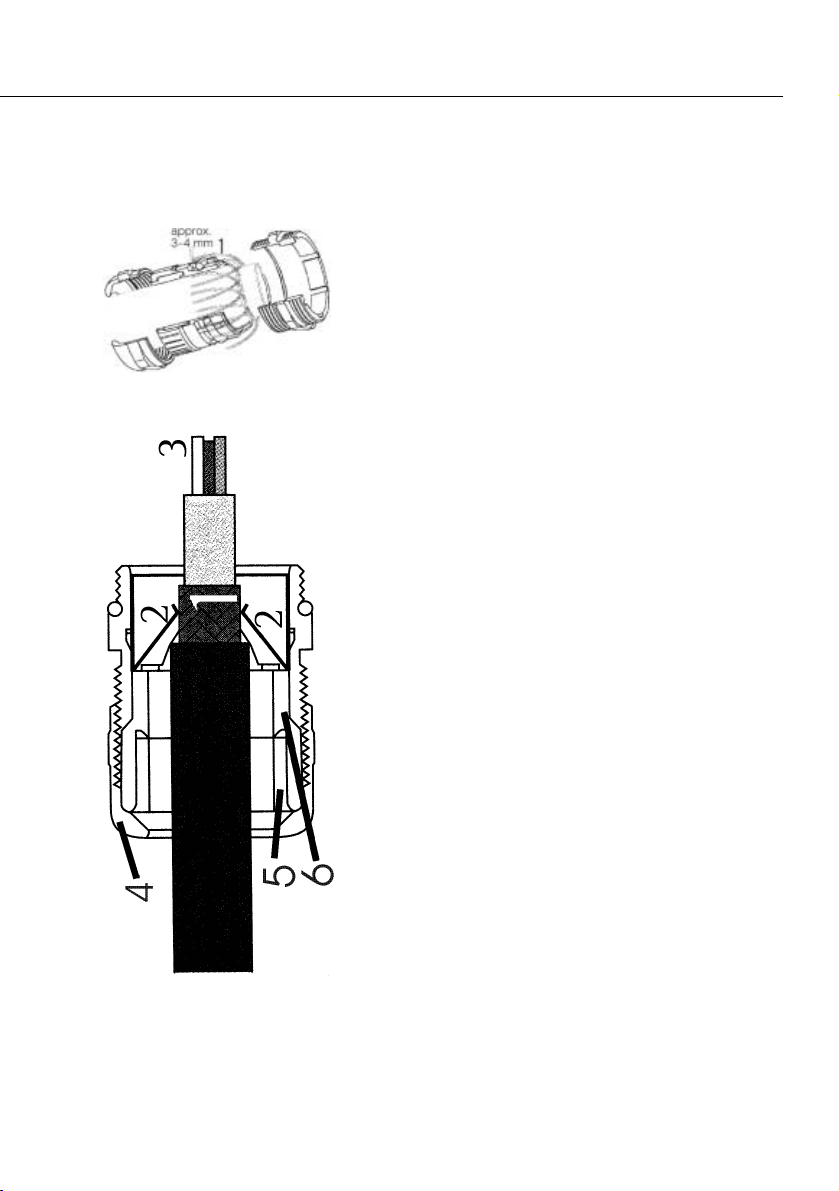
6Installing the Filling Module
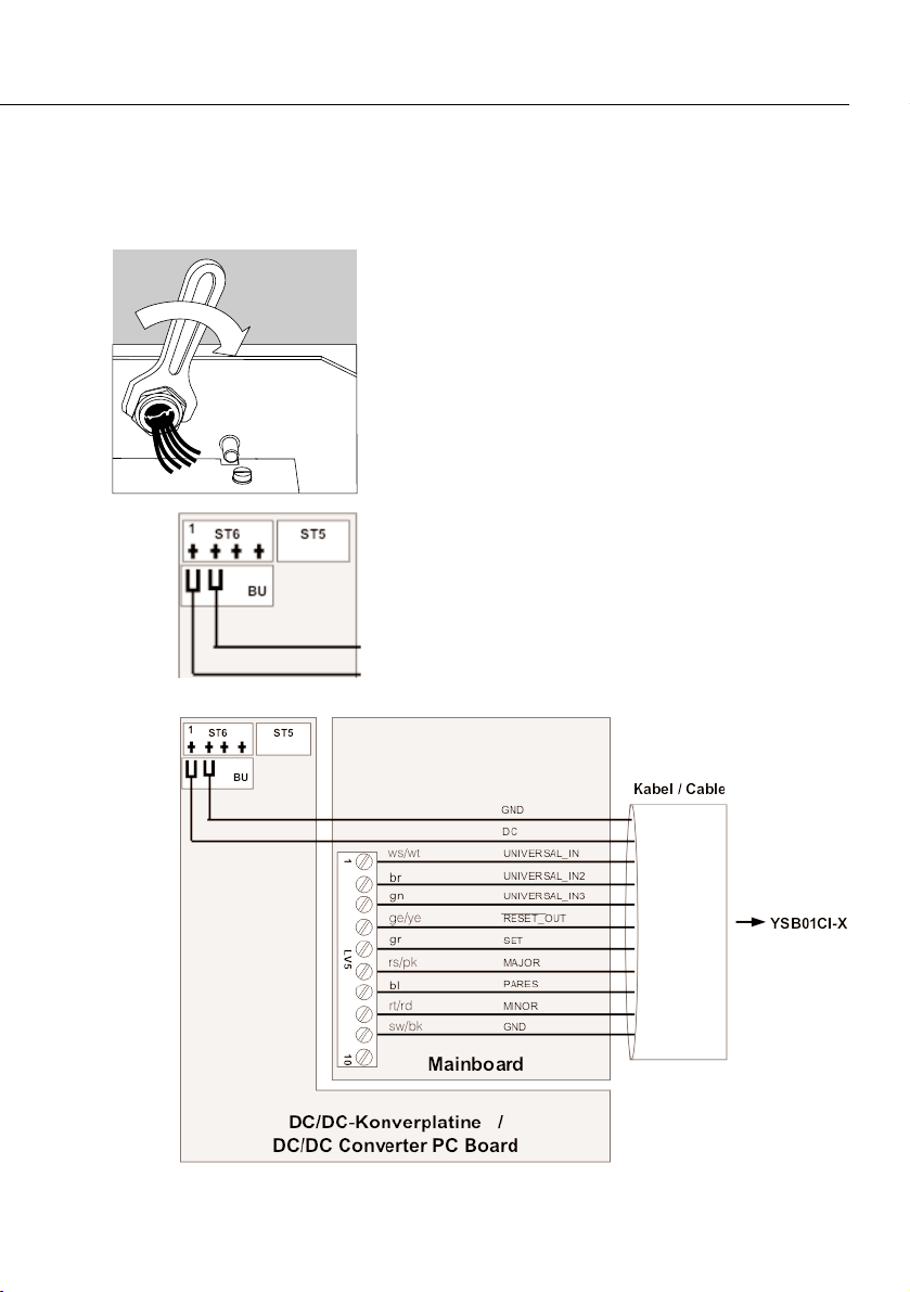
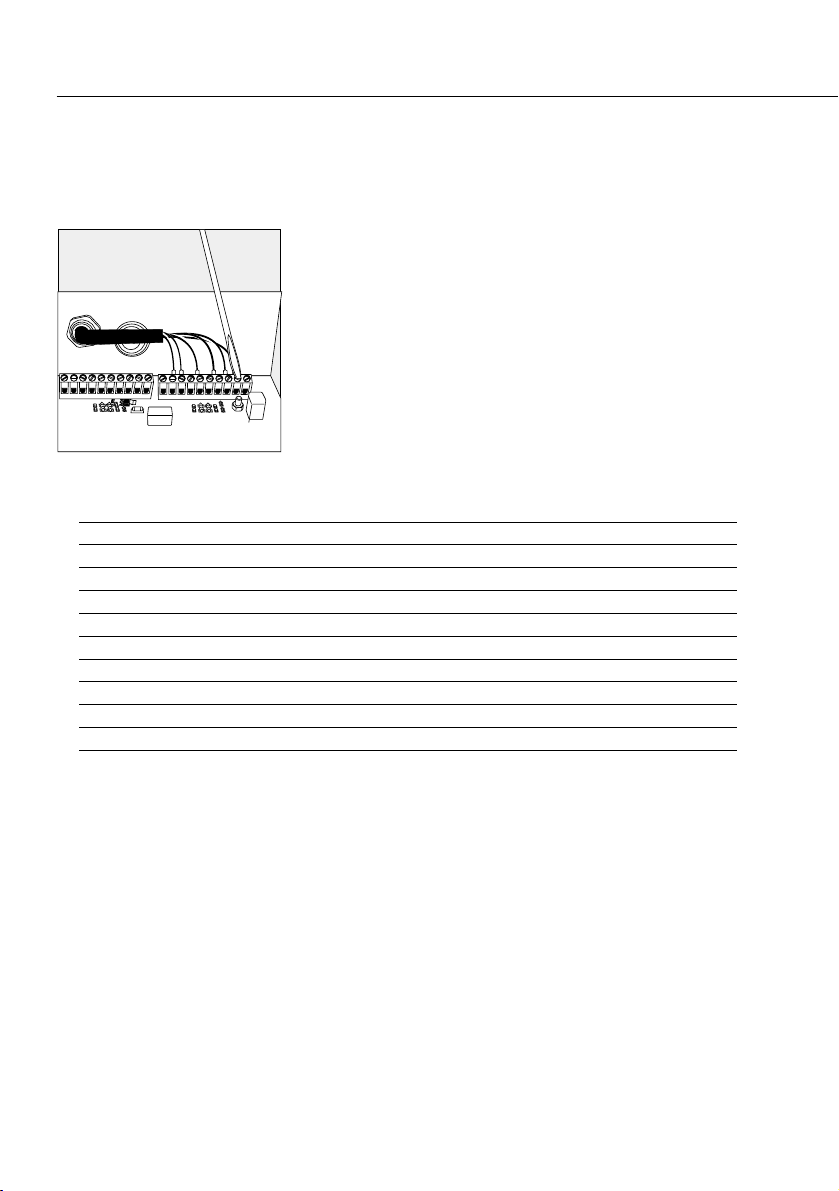
12 Installing the Filling PCB
15 Specifications
15 Accessories
16 Documents for Hazardous Areas
The following symbols are used in
these instructions:
§indicates required steps
$indicates steps required only under cer-
tain conditions
> describes what happens after you have
performed a particular step
– indicates an item in a list
!indicates a hazard
Equipment Supplied
– Filling module with filling PCB
or
– Filling PCB for CIXS3 indicator
– The equipment complies with Directive
94/9/EC for use in the following hazardous
areas: Zone 1 and 2 (gases) and Zone 20, 21
and 22 (dusts).
– When used in hazardous area in which com-
bustible dusts are present, the IP65 protection
of the equipment must be intact. For this
reason, it is essential that installation and
maintenance are performed with extreme care;
in particular:
– Make sure all seals are installed
– bserve all instructions carefully when
installing the cover
– Tighten all fastening screws
– Tighten all cable glands and make sure they
are installed in accordance with instructions
– The filling module must be disconnected from
power before the housing is opened. To do
this, unplug the power cord on the equipment
that powers the filling module (e.g., Combics
indicator).
Connect the filling module only to equipment
approved for this purpose by Sartorius.
– There is an M4 threaded rod on the filling
module for connecting a grounding conductor.
Make sure to ground (earth) the filling module.
– The filling module may be operated only within
an ambient temperature range of –20°C to
+40°C (–4°F to +104°F).
– When used in a hazardous area in which
combustible dusts are present, clean the filling
module regularly to prevent excessive build-up
of dust. In a Zone 20 hazardous area, the max-
imum permissible dust layer thickness is 5 mm.
– Installation, maintenance and repair work
should be performed only by service techni-
cians trained and authorized by Sartorius.
Any work that is not performed in accordance
with these instructions and acknowledged
technical standards will result in forfeiture of
the approval for use in hazardous areas, and of
all claims under the manufacturer’s warranty.
– Make sure to observe all national laws and
regulations governing the use of such equip-
ment. Ask your supplier for information on the
legal regulations applicable in your country.