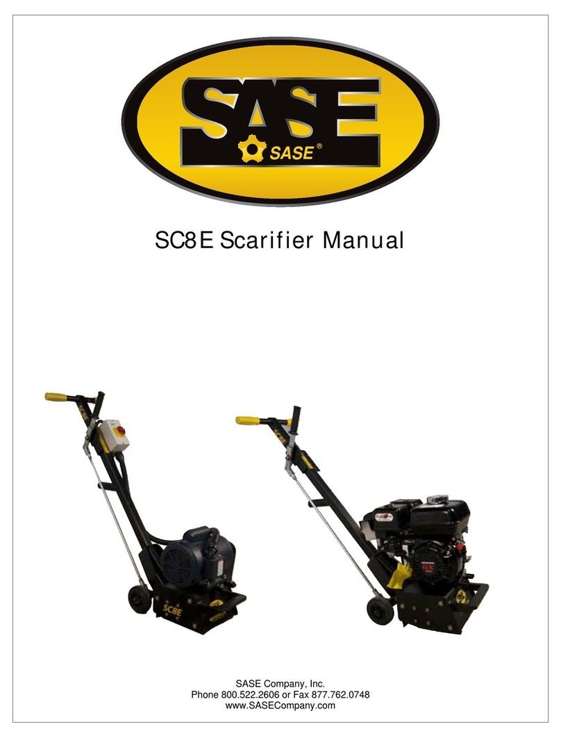
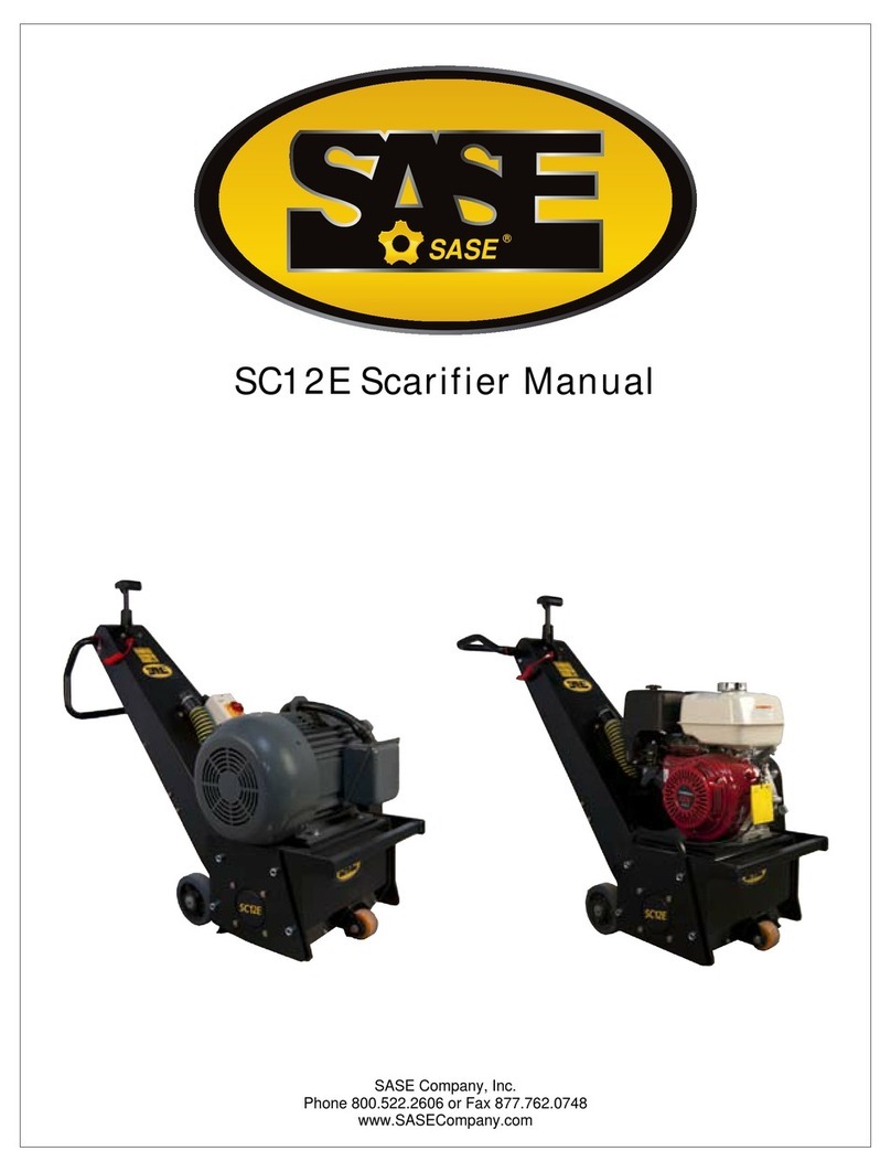
Sase SC320 User manual

Instruction manual (USA)
SASE

-3-
Declaration of Conformity according to EN ISO/IEC 17050-1
EC-Declaration of Conformity
Month.Year: .
For the machine described below
Product denomination:
Model:
Serial number:
Floor Planer
SC 320
Herewith we declare, thatthe machine is complying with all the essential requirements of the
Machine Directive 2006/42/EC of the EUROPEAN PARLIAMENT of the 17th of Mai 2006
The person authorized to compile the relevant technical documentation (According to Appendix II Nr.
1. A. Nr. 2, 2006/42/EG):
Name, Surname: Greb, Johannes
reganaMlacinhceT:noitcnuF
ynamreG,frodslA81575,71geWreueN:sserddA
More information on the compliance with the directive is contained in Appendix 1.
This Declaration is given by the manufacturer:
Name: Contec
®
Maschinenbau & Entwicklungstechnik GmbH
Address: Hauptstraße 146, 57518 Alsdorf, Deutschland / Germany
Given by:
Name, Surname: Greb, Johannes
reganaMlacinhceT:noitcnuF
Alsdorf, 22.12.2010
Place/Date Signature
Appendix 1 of the Declaration of Conformity
Month.Year: .
For the machine described below
Product denomination:
Model:
Floor Planer
SC 320
Herewith we declare, thatthe machine is complying with all the essential requirements of the:
Directive 2004/108/EC of the EUROPEAN PARLIAMENT of the 15th of December 2004 on
Electromagnetic Compatibility
Directive 2006/42/EC of the EUROPEAN PARLIAMENT of the 17th of Mai 2006
Harmonised Standards used:
EN 12100 - 1 „Safety of Machinery – Basic concepts“
EN 12100 - 2 „Safety of Machinery – Technical principles”
SASE
Instruc on manual SC320

-4-
2. Machine applications
Planing of horizontal, dry floors such as concrete and steel surfaces with or without a coating
and asphalt using SASE
®
planing tools. The use of the machine outside is only possible in
dry weather.
3. Technical Data
3.1 Planer
023CS
)ni5.21(mm023tucfohtdiW
)ni42(mc16htdiW
)ni34(mc011htgneL
Height with handle 110 cm (43 in)
Weight with drum 230 kg (507 Ibs)
)ni68.2(mm07¢troptsuD
Height Adjustment Hand wheel and lever
Vibration damped handle Rubber block on handle
bracket
)ph5.71(Wk2.31,V064rotomcirtcelE
ph31lortepadnoH
tseuqernOsrotoMrehtO
Average value of acceleration a
hv
* 8,6 m/s
2
Noise level L
wa
* 109 dB(A)
Noise level Leq * 96 dB(A)
* Data: VÜA Verein zur Überwachung technischer Anlagen e.V.
3.2 Tools
)ni5.8(mm012retemaidmurD
Cutter shaft diameter 20 mm (0.82 in)
Number of shafts 6
8/08rettuCTCT
02/08rettucgnilliM
All specifications are approximate and subject to confirmation. They should only be used as a
guide.
SASE
Instrucon manual SC320

-5-
4. Applications of the tools
cllarofsrettucefilgnol,ytudyvaeHsrettuCTCT oncrete
texturing, scabbling, planing and grooving
applications. Also used for removal of road
markings, roof chippings and brittle coatings
omrehtfolavomerehtrofyliramirPsrettucgnilliM plastic
road / runway markings. Tipped with tungsten
carbide they are cost effective and highly
efficient. A range of cutter dimensions are
available.
folavomerehtrofsrettucdetaerttaeHslialfmaeB paint
coatings and laitance from new concrete. Also
for removing grease, dirt and ice deposits.
5. Safety rules
Attention ! The SC 320 floor planer is constructed according to existing safety rules and
regulations. These technical precautions should not be removed or changed
under any circumstances. While operating the machines the following items
should also be kept in mind:
1. The planers should always be operated with all safety covers and technical precautions.
2. The operator should never leave the machine during operation.
3. Before leaving the machine all rotary parts should be brought to a stand still. The electric
models must be disconnected from the mains. Make sure that the machine cannot roll or
move by itself.
4. After maintenance and adjustment all safety covers must be reattached.
5. If the noise level exceeds 90 dB(A) ear protectors must be worn.
6. In the event of a large amount of dust during operation connect a dust collector to the
planer.
SASE
Instrucon manual SC320

-6-
6. Operating
a. After mounting the appropriate tools the operation of the planer can begin.
b. The lever of the height adjustment (Appendix diagram No. 97 and 99) has to be in
the upper position before the machine is switched on. The hand wheel of the height
adjustment must also be turned anti-clockwise as far as possible.
c. Switch the motor on. Lower the planer with the lever to the operating position.
Turn the hand wheel of the height adjustment until the tools are lowered to the
floor and until you achieve the required finish.
Attention: Lowering the tools too much decreases the performance of the machine. You
will also destroy the shafts in the drum and the bearings of the machine.
Attention: Never switch the motor of the planer on while the tools still touch the floor.
Always lift the machine and the tools clear from the floor and then switch the motor on.
d. Heavy dust can be avoided by connecting a dust collector to the dust port.
e. The vibration damped handle bar ensures an easier operation.
7. Changing the drum
Attention: Before any maintenance, the machine must be brought to a complete stand still.
Always disconnect the machine if it is an electric model.
- Lift the machine with the hand wheel so that the tools are well clear of the floor.
- Unscrew the screws on the right side plate (M10, Key width 17 mm)
- Carefully remove the side plate (Appendix diagram No. 97 and 99).
- Take out the drum. Remove worn out tools. Check shafts and drums concerning wear and
tear. If necessary replace new tools on the drum.
- Push drum on freshly greased shaft.
- Reconnect right side plate.
SASE
Instrucon manual SC320

-7-
8. Adjusting the drum
During the operation of the SC 320 floor planer or after a drum has been changed or replaced,
the drum shaft and the rear wheel axis can fall out of alignment. This results in an uneven
track on the floor. On one side the drum touches the floor before the other and therefore
removes more surface material on this side.
The two rear wheels are mounted on an eccentric shaft (see diagram).
Rear Wheel
Clockwise
Clamping Screw
If the drum has to be adjusted proceed as follows:
Place the planer on an even floor. Lift the machine with the height adjustment hand wheel,
until all the tools are well clear of the floor. Loosen the clamping screw of the eccentric shaft.
On the other side of the rear wheel is a screw which keeps the wheel on the shaft. Turning the
screw will also turn the eccentric shaft. The floor planer moves up and down on one side.
Always turn the screw clockwise. Anti clockwise would loosen the screw. Keep turning until
all the tools on the drum are the same distance to the floor. Tighten the clamping screw again.
9. Maintenance and cleaning
9.1 Bearings
All bearings are greased for their life time.
9.2 Height adjustment and joints
All joints have to be greased periodically with a standard machine grease.
SASE
Instrucon manual SC320

-8-
9.3 Belt drive
Check the belt after approximately every 30 hours of operation. The belt is tensioned
automatically by a tensioner wheel underneath the belt cover.
9.4 Cleaning
A regular cleaning of the machine increases the life of all components and tools of the planer.
10. Diagram
1 1
3 2 3 2
4 4
1 Handle bar 2 Height adjustment hand wheel
3 Lever of the height adjustment 4 Rear wheel
11. Appendix
Diagrams
Wire diagram
Tools
Part list
SASE
Instrucon manual SC320


Table of contents
Other Sase Lawn And Garden Equipment manuals
Popular Lawn And Garden Equipment manuals by other brands

Swisher
Swisher 2645 CORRUGATED PLOW BLADE manual

Buhler
Buhler Farm king FK368 Operator's & parts manual

HAPPY LITTLE STORE
HAPPY LITTLE STORE EARTHWORM FACTORY Instruction guide

Grange
Grange 220907A001OSBZ04C1 manual

EINHELL
EINHELL GC-SC 36/31 Li Original operating instructions

Arcadia
Arcadia Mobile raised bed Assembly instructions