SAS/op/proc/forks/op manuals/vulturewireextractor.pub 6/18/2018 v2 Page 5 © 2014-2018 S.A.S. of Luxemburg, LLC.
S.A.S. of Luxemburg, LLC., 133 Center Drive Hwy 54, PO Box 260, Luxemburg, WI 54217 USA
Phone: 920-845-2198 1-877-SAS-FORK Fax: 920-845-2309 Web: www.sasforks.com
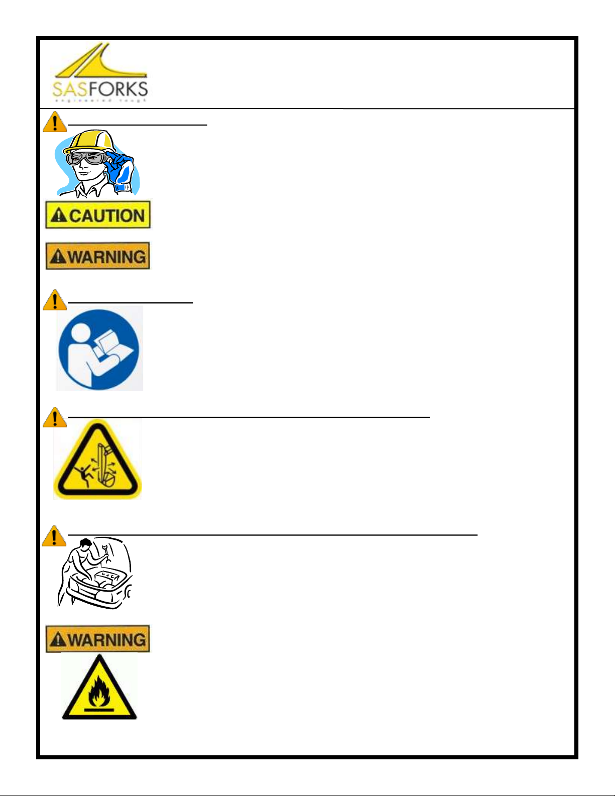
Serious bodily injury, death and property damage can caused by an operator that is
under the influence of drugs or alcohol (of any type, illegal, prescribed or over the
counter) due to impaired operator judgment. Do not operate when impaired.
Consult your physician before operation of this equipment while on medication.
Inspect the device and perform all preventative maintenance before operation at the
start of every work shift. Failure to perform inspections or proper maintenance can
result in equipment failure resulting in serious injury or property damage.
This equipment has numerous moving components. Operate only from the cab
equipped with safety glass windshield and adequate protective steel guard while
seated and wearing a safety belt. Be aware of potential pinch points and keep clear
during operation, inspection and maintenance. Pinch points exist between grapple
attachment jaws, cab swing, hold down arms and others, failure to keep clear while
in operation can result in serious injury or death.
Do not exceed posted weight limits on equipment. Exceeding rated load limits will re-
sult in equipment damage, loss of steering control, machine tip over, serious injury or
death.
Not designed to be operated in an explosive environment. Only use this equipment
in well ventilated areas, a sufficient distance away from flammable or explosive gas-
es, liquids or substances to avoid risk of ignition. Operating in an explosive environ-
ment may cause an explosion and fire, resulting in injury, death, property damage.
Operation of equipment by un-qualified or un-trained individuals can result in seri-
ous injury or death. All operators must be properly trained prior to operation.
Installation & operation of equipment should only be performed by qualified and trained individuals. All per-
sons operating or working in the area of operation should read this manual. A copy of this manual should
be kept with the equipment. A qualified operator will operate the machine safely in accordance with, and:
Understand the written instructions supplied by the manufacturer of the device, the manufacturer of
the excavator, all company rules and any applicable OSHA or regulatory governing body regulations.
Completed training including actual operation of the device and excavator to which it is attached.
Know and follow the safety rules and regulations of the jobsite.
GENERAL SAFETY GUIDELINES (PAGE 5)
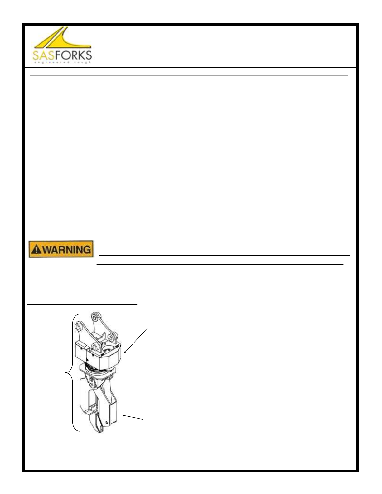
SAS™ Vulture Wire Extractor
This equipment is operated by high pressure hydraulics. Hydraulics are a stored
power source and as such must be treated as energized at all times. Be certain
pressure has been relieved prior to handling, inspecting or performing maintenance
on this unit. Follow lockout tag out procedures and release all stored energy before
servicing equipment. Failure to release energy or disable hydraulic energy can re-
sult in serious injury or death. High pressure fluids can also discharge at great ve-
locity and cause injection into skin. Wear safety glasses and appropriate gloves
while inspecting, operating and maintaining this equipment.