Satel AMD-100 User manual

®
WIRELESS MAGNETIC CONTACT
AMD-100
amd100_en 05/10
The AMD-100 wireless magnetic contact is designed for operation as part of the ABAX two-
way wireless system. This manual applies to the device with electronics version 3.5 J or later
which is supported by the ACU-100 controller with software version 1.06 or later and by the
INTEGRA 128-WRL control panel.
The AMD-100 magnetic contact sends information on violation
when the magnet is moved outside the reed switch operating range
or the additional input terminals are opened. Two reed switches are
used in the device and you can program by radio which of them is
to be active.
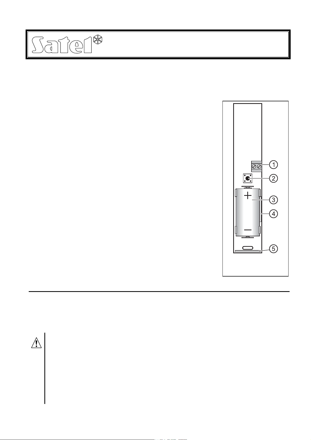
Descriptions of Figure 1:
1 – additional NC type input terminals for connecting a hardwired
detector. The additional input is connected in series with the
reed switches on the electronics board. If the input is not used,
its terminals should be shorted.
2 - tamper contact, which responds to opening the housing and
pulling it off from the surface.
3 - CR123A 3 V lithium battery which ensures operation for
approx. 3-year period. The device controls the battery status.
When the voltage drops to 2.6 V, the "low battery" information
is sent. The low battery signaling continues until the battery is
replaced.
4 - location of the side reed switch (mounted on the other side of
the electronics board).
5 - location of the bottom reed switch (mounted on the other side
of the electronics board).
The LED indicator is only "on" in the test mode, indicating
communication (during polling), violation and tamper.
1. INSTALLATION
The device is designed for indoor installation. If the magnetic contact is used for the
protection of window or door, the detector should be mounted on the window/door frame, and
the magnet in/on the window sash or door leaf. Mounting the contact on ferromagnetic
surfaces and/or near to strong magnetic and electrical fields is not advisable, because it can
result in malfunctioning of the device.
Before you mount the device permanently, check the level of signal received
from the device by the ACU-100 controller or by the INTEGRA 128-WRL control
panel and, if necessary, change the place of installation so that the location is
optimal in terms of communication.
Install the battery inside the device just before registering it in the ABAX
system. If unregistered or having no communication with the ABAX system, the
device will consume more energy, which will reduce the battery life.
Be particularly careful during installation so as not to make damage to the reed
switches on the electronics board.
1. Open the housing .
Fig. 1. View of the
device PCB.

SATEL AMD-1002
2. Install the battery and add the device to the wireless system (see the ACU-100 controller
manual, INTEGRA 128-WRL control panel installer manual or VERSA control panel
installer manual). A label with 7-digit serial number that should be entered during
registration of the device in the system is provided on the electronics board.
3. Fasten the detector temporarily at the place of its future installation.
4. Check the level of signal received from the magnetic contact. If necessary, select another
place for installation.
5. If a hardwired detector is to be connected to the additional input terminals, make a hole in
the rear panel of the housing and pull the cables through it (maximum permissible cable
length being 3 meters). Screw the cables to the input terminals.
6. Fasten the housing rear panel to the mounting surface.
7. Close the magnetic contact housing.
8. Secure the magnet, taking into account the maximum permissible distance from the reed
switch (see Fig. 2).
110 mm
26 mm
20 mm 24 mm
23 mm
27 mm
2
A
20 mm
B
15 mm
1
15 mm
Fig. 2. Housing dimensions, position and maximum operating ranges of reed switches. The
shown ranges refer to magnet placed at the height of electronics board.
1 – bottom reed switch. 2 – side reed switch. 3 – spring of tamper contact.
9. Configure the magnetic contact to suit your requirements. For information on configuration
– see the ACU-100 controller manual and the INTEGRA and VERSA control panel
programming manuals.

AMD-100 ABAX 3
10.Start remotely the test mode and check that the magnetic contact responds appropriately
to moving the magnet away, and that signal is being sent from the additional input.
11.Exit the test mode. The magnetic contact is now ready for work.
2. SPECIFICATIONS
Operating frequency band ...................................................................868.0 MHz ÷ 868.6 MHz
Radio communication range ............................................................ up to 150 m (in open area)
Additional input sensitivity.............................................................................................. 312 ms
Power supply .................................................................................. lithium battery CR123A 3 V
Battery life expectancy...................................................................................... approx. 3 years
Current consumption, standby ..........................................................................................50 µA
Current consumption, maximum ......................................................................................16 mA
Security grade according to EN50131-2-6.................................................................... Grade 2
Environmental class according to EN50130-5 ......................................................................... II
Operating temperature range...............................................................................-10°C...+55°C
Maximum humidity.......................................................................................................... 93±3%
Complied with standards........EN 50130-4, EN 50130-5, EN 50131-1, EN 50131-2-6, EN 50131-5-3
Housing dimensions ..........................................................................................24x110x27 mm
Weight................................................................................................................................. 58 g
Be particularly careful when replacing the battery. If inappropriately done,
replacement of the battery may lead to a risk of explosion. The Manufacturer
bears no responsibility for any consequences of incorrect replacement of the
battery.
Always use the CR123A 3V lithium batteries.
The used batteries must not be discarded, but should be disposed of in
accordance with the existing rules for environment protection.

DECLARATION OF CONFORMITY
1471
Product:
AMD-100 – Wireless Magnetic Contact for
ABAX System
Manufacturer: SATEL spółka z o.o.
ul. Schuberta 79
80-172 Gdańsk, POLAND
tel. (+48) 0-58 320-94-00
fax. (+48) 0-58 320-94-01
Product description:Magnetic contact intended for use with ABAX wireless alarm system
components, operating in the 868.0MHz – 868.6MHz frequency band. Device is intended for
installation in intruder alarm systems.
This product conforms to the following EU Directives:
R&TTE 1999/5/EC
This product meets requirements of the harmonized standards:
R&TTE: ETSI EN 300 220-1: v.1.3.1; ETSI EN 300 220-3: v.1.1.1;
EMC: ETSI EN 301 489-1: v.1.5.1.; EN 301 489-3: v.1.4.1
Safety: EN60950-1:2004
Notified body taking part in conformity evaluation:
Identification No.: 1471
Gdańsk, Poland 2005-07-15 Head of Test Laboratory:
MichałKonarski
The latest EC declaration of conformity and product approval certificates are available for
downloading on website www.satel.pl
SATEL sp. z o.o.
ul. Schuberta 79
80-172 Gdańsk
POLAND
tel. + 48 58 320 94 00
www.satel.pl
Table of contents
Other Satel Accessories manuals