Satel AMD-102 User manual

®
WIRELESS MAGNETIC CONTACT WITH INPUT
FOR ROLLER SHUTTER DETECTOR
AMD-102
amd102_en 11/12
The AMD-102 wireless magnetic contact is designed for operation as part of the ABAX two-
way wireless system. The device is supported by the ACU-100 controller with firmware
version 2.01 or later and by the INTEGRA 128-WRL control panel with firmware version 1.07
or later. This manual applies to the magnetic contact with electronics version 1.3 or later.
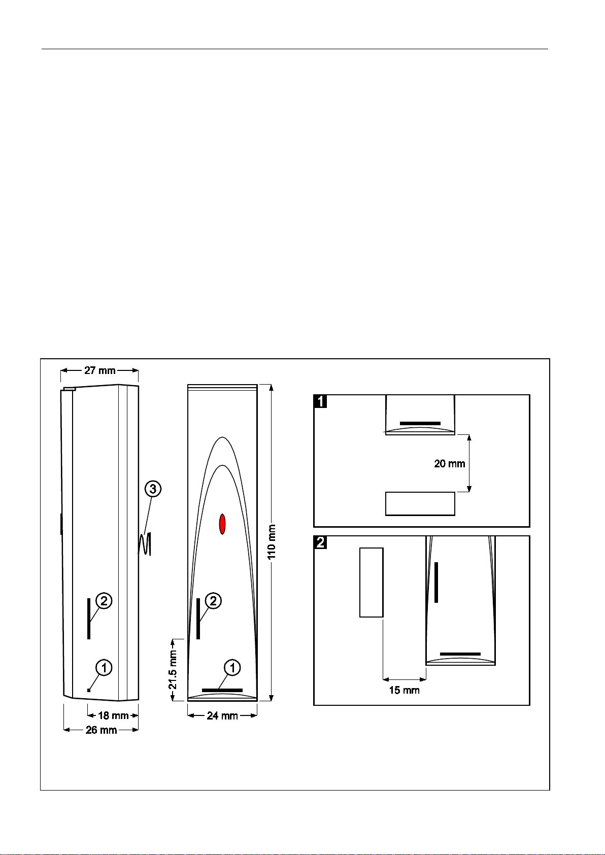
Two reed switches are employed in the magnetic contact. You can
program by radio which of them is to be active. The magnetic
contact has two additional inputs (one NC type and the other one
for roller shutter detector). It occupies two positions in the ABAX
system (first: magnetic contact; second: additional inputs).
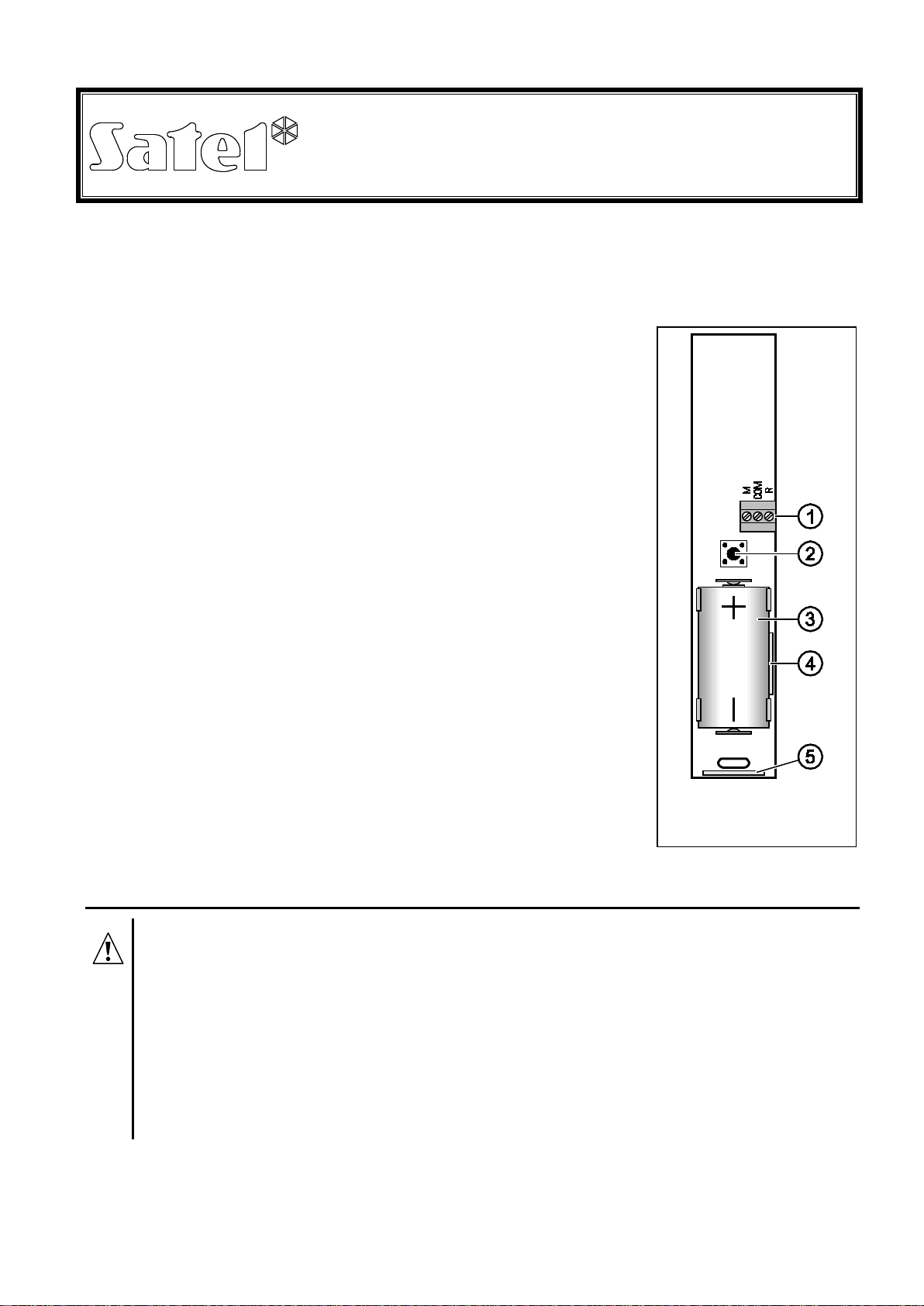
Explanations for Fig. 1:
1 - additional input terminals:
R- input for roller shutter detector
COM - common ground
M- NC type input
2 - tamper contact which reacts to opening and/or tearing off the
housing from its mounting surface.
3 - CR123A 3 V lithium battery, ensuring operation for approx.
3-year period. The device monitors the battery status. When the
voltage drops to 2.6 V, a low battery message is sent. Indication
of the low battery status will continue until the battery is
replaced.
4 - location of the side reed switch (mounted on the other side of
the electronics board).
5 - location of the bottom reed switch (mounted on the other side
of the electronics board).
The LED indicator is only "on" in the test mode, indicating
communication (during polling), violation and tamper.
1. Installation
Before you mount the magnetic contact permanently, check the level of signal
received from the device by the ACU-100 controller or by the INTEGRA 128-WRL
control panel and, if necessary, change the place of installation so that the
location is optimal in terms of communication.
Install the battery inside the magnetic contact just before registering it in the
ABAX system. If unregistered or having no communication with the ABAX
system, the device will consume more energy, which will reduce the battery life.
Be particularly careful during installation so as not to make damage to the reed
switches on the electronics board.
The magnetic contact is designed for indoor installation. The detector should be mounted on
a fixed surface (e.g. window or door frame), and the magnet on a movable surface (e.g.
window or door). Mounting the magnetic contact on ferromagnetic surfaces and/or near to
Fig. 1. View of detector
electronics board.

2 AMD-102 SATEL
strong magnetic and electrical fields is not advisable, because it can result in malfunctioning
of the device.
1. Open the housing.
2. Install the battery and add the magnetic contact to the wireless system (see the ACU-100
controller user manual, INTEGRA 128-WRL control panel installer manual or VERSA
control panel installer manual). A label with 7-digit serial number that should be entered
during registration of the device in the system is provided on the electronics board.
3. Fasten the detector temporarily at the place of its future installation.
4. Check the level of signal received from the magnetic contact. If necessary, select another
place for installation.
5. Make a hole in the rear panel of the housing and pull the cables through it (the maximum
permissible cable length is 3 meters). Screw the cables to the corresponding terminals on
the electronics board.
Note: The input to which the detector is not connected must be shorted to ground.
6. Fix the rear panel of housing to the mounting surface.
7. Close the magnetic contact housing.
8. Fix the magnet, taking into account the maximum permissible distance from the reed
switch (see Fig. 2).
Fig. 2. Housing dimensions, position and maximum operating ranges of reed switches. The
shown ranges refer to magnet placed at the height of electronics board.
1 – bottom reed switch. 2 – side reed switch. 3 – spring of tamper contact.

SATEL AMD-102 3
9. Configure the magnetic contact:
– for the magnetic detector, define which of the two reed switches is to be active;
– for the input for roller shutter detector, program the pulse count (the number of pulses
after which the input will be violated) and pulse validity duration (the time counted from
the pulse occurrence, during which next pulses must occur for the input to become
violated).
For detailed information regarding configuration, please refer to the ACU-100 controller
user manual and the INTEGRA and VERSA control panel programming manuals.
10.Start the test mode and make sure that the magnetic contact responds appropriately to
moving the magnet back and that information on violation of the additional inputs is sent.
11.Exit the test mode. The magnetic contact is now ready for work.
12. Specifications
Operating frequency band ...................................................................868.0 MHz ÷ 868.6 MHz
Radio communication range (in open area)............................................................up to 500 m
Additional NC input sensitivity........................................................................................ 312 ms
Power supply.................................................................................lithium battery, CR123A 3 V
Battery life expectancy...................................................................................... approx. 3 years
Current consumption, standby..........................................................................................50 µA
Current consumption, maximum......................................................................................16 mA
Security grade according to EN50131-2-6....................................................................Grade 2
Environmental class according to EN50130-5.........................................................................II
Operating temperature range........................................................................... -10 °C …+55 °C
Maximum humidity..........................................................................................................93±3%
Complied with standards........EN 50130-4, EN 50130-5, EN 50131-1, EN 50131-2-6, EN 50131-5-3
Housing dimensions ......................................................................................24 x 110 x 27 mm
Weight.................................................................................................................................56 g
Always use the CR123A 3V lithium batteries.
Be particularly careful when replacing the battery. If inappropriately done,
replacement of the battery may lead to a risk of explosion. The Manufacturer
bears no responsibility for any consequences of incorrect replacement of the
battery.
The used batteries must not be discarded, but should be disposed of in
accordance with the existing rules for environment protection.

DECLARATION OF CONFORMITY
Product:
AMD-102 – Wireless magnetic contact
Manufacturer: SATEL spółka z o.o.
ul. Schuberta 79
80-172 Gdańsk, POLSKA
tel. (+48) 58 320-94-00
fax. (+48) 58 320-94-01
Product description:Magnetic contact intended for use with ABAX wireless alarm system
components with additional analyzed input for connecting external roller shutter detector, operating at
868MHz. Device is intended for installation in intruder alarm systems.
The product is in conformity with the following EU Directives:
R&TTE 1999/5/EC
The product meets the requirements of harmonized standards:
ETSI EN 300 220-1: v.2.1.1; ETSI EN 300 220-2: v.2.1.2
ETSI EN 301 489-1: v.1.6.1.; EN 301 489-3: v.1.4.1
EN60950-1:2006
Notified entity participating in the conformity assessment:
Identification No.: 1471
Gdańsk, Poland 2009-05-09
Head of Test Laboratory:
Michał Konarski
The latest EC declaration of conformity and product approval certificates are available for
downloading on website www.satel.pl
SATEL sp. z o.o.
ul. Schuberta 79
80-172 Gdańsk
POLAND
tel. + 48 58 320 94 00
www.satel.pl
Other manuals for AMD-102
1
Table of contents
Other Satel Accessories manuals
Popular Accessories manuals by other brands

Endress+Hauser
Endress+Hauser omnigrad M TR 44 technical information

Hudora
Hudora 65138 INSTRUCTIONS ON ASSEMBLY AND USE

Eurotronic
Eurotronic Air Quality SensorZ-Wave Plus Installation & operation guide

GCS
GCS ZA1501IN-5 Installation & operation manual

Texas Instruments
Texas Instruments OPT3006EVM user guide

DuoKui
DuoKui P1 manual