Select ANTENNA SETUP, Press OK
Select Satellite and choose Galaxy25Ku 97W by pressing LEFT
or RIGHT ARROW, Select LNB Type and set to LNB-10750
(Standard), Select Transponder and press the RIGHT ARROW to
select an Active Transponder (example: 12177 V 23.000), Select
Positioner and set to USALS, Press OK
Select LONGITUDE and enter your installation location
Longitude using the Numeric Keys Use the RIGHT ARROW to
select if the location is entered as EAST or WEST Longitude
(North American coordinates are entered as West). Example
Sacramento, CA enter 121.2W.
Select LATITUDE and use the Numeric Keys to enter the install
location Latitude. Use the RIGHT ARROW to select if the
location is entered as NORTH or SOUTH (North American
coordinates are entered as North). Example: Sacramento, CA enter
38.5N. Select “Go to position” and Press OK. The dish will rotate to the Galaxy25 satellite position
based on the calculated values.
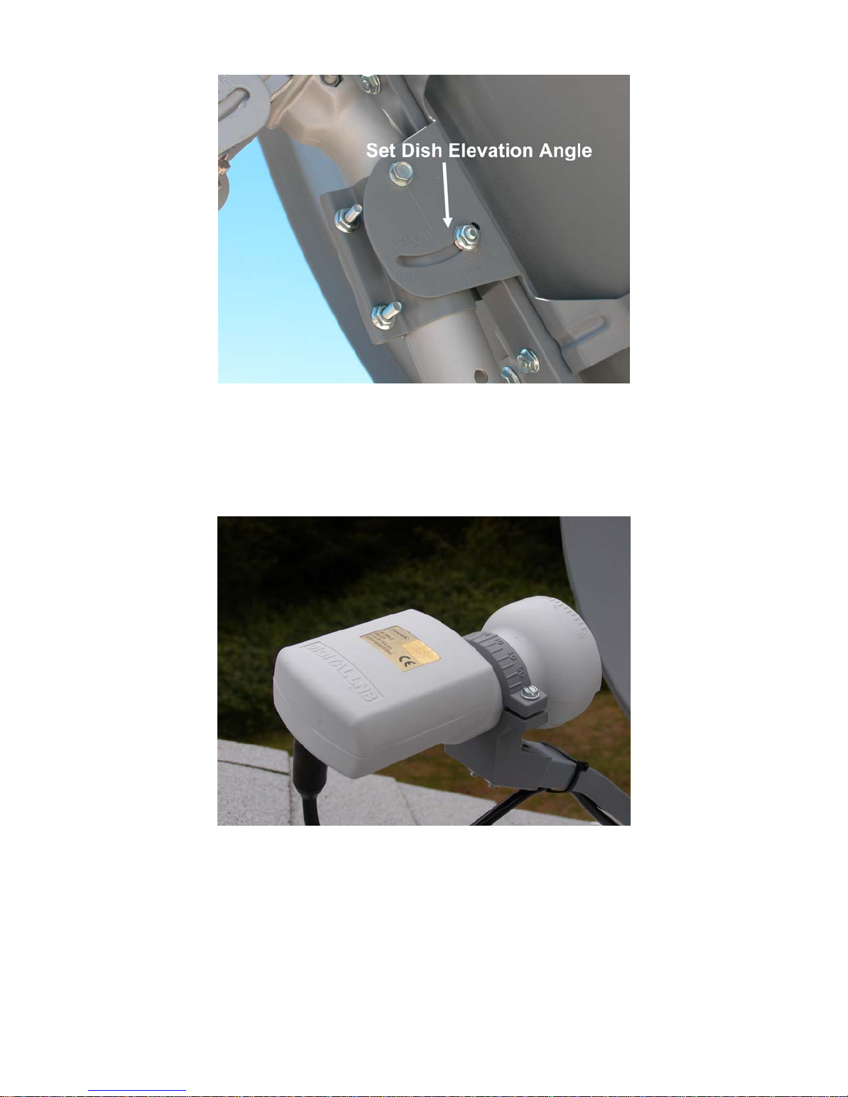
Slightly loosen the motor on the mounting mast and rotate the motor assembly East or West on the post
in very small movements while observing the Signal Quality meter. If a Signal Quality reading cannot
be obtained or if the Quality is low or erratic, raise or lower the Satellite Dish Elevation by a degree and
repeat the slow pan left or right rotation. Once the satellite is located, the Signal Quality reading will be
displayed.
The Fortec Star Mercury displays reliable programming if the
Signal Quality is at least 50%. The higher the Signal Quality
reading, the more reliable reception. Transponder 12177 should be
65% or better.
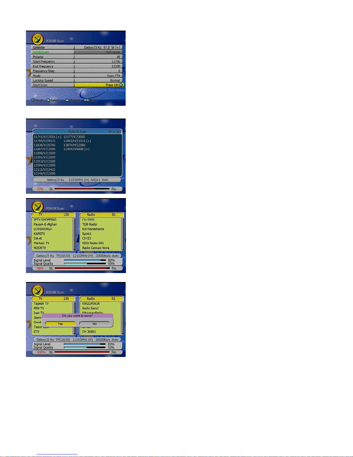
Press the P.SCAN KEY to select Power Scan to find all available
TV and Radio channels on the Galaxy25 Ku satellite.