manuals.online logo
Brands
  1. Home
  2. •
  3. Brands
  4. •
  5. sauermann
  6. •
  7. Thermometer
  8. •
  9. sauermann VT 210 User manual

sauermann VT 210 User manual

1
USER MANUAL
VT 210
THERMO-HYGROMETER-ANEMOMETER
Table of contents
1. PRESENTATION...........................................................................................................................................................5
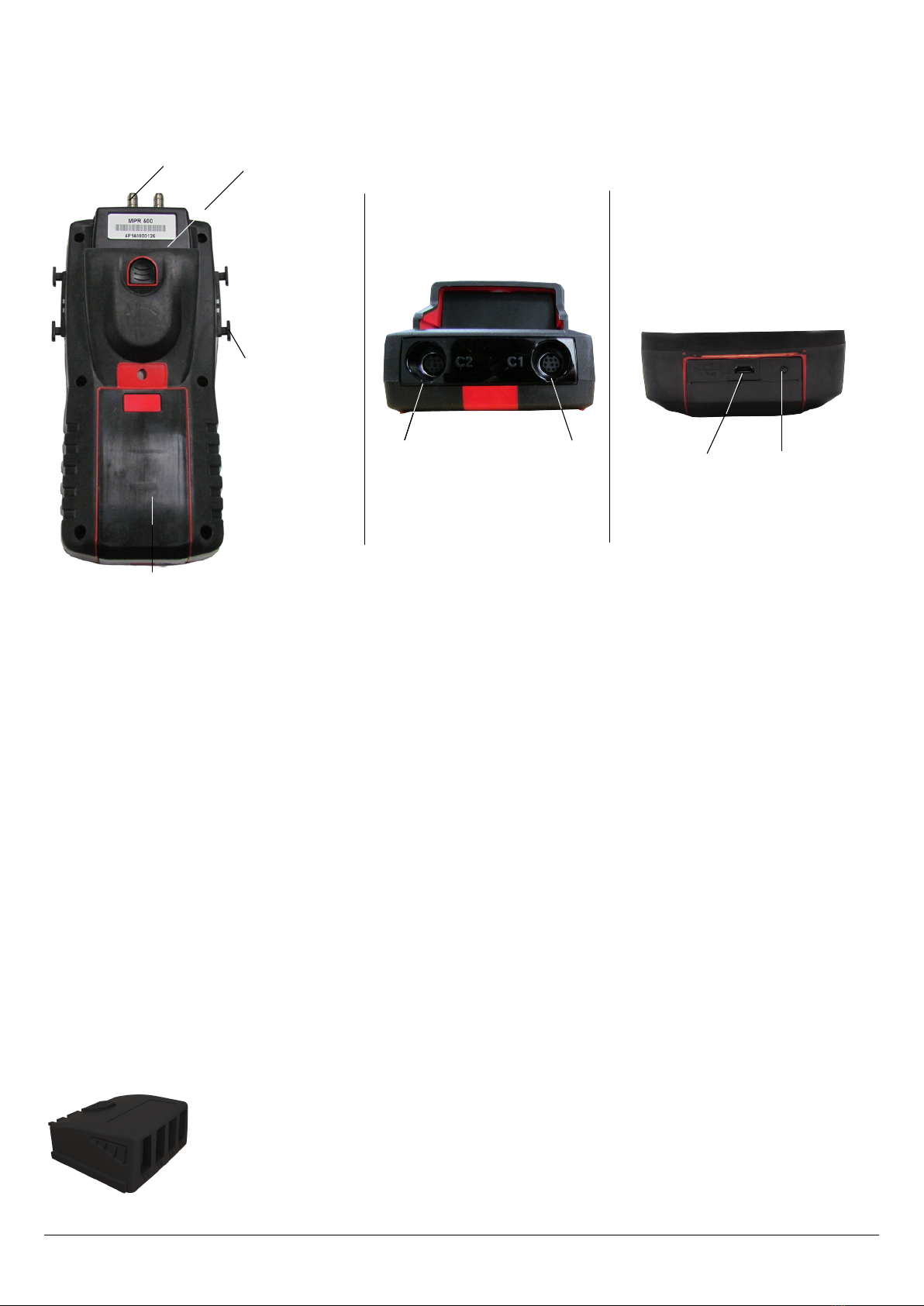
1.1 . Instrument description.........................................................................................................................................5
1.2 . Key description....................................................................................................................................................5
1.3 . Remove b ttery...................................................................................................................................................6
1.4 . Directive 2014/53/EU..........................................................................................................................................6
2. CONNECTIONS OF THE VT 210....................................................................................................................................7
2.1 . M in fe tures......................................................................................................................................................7
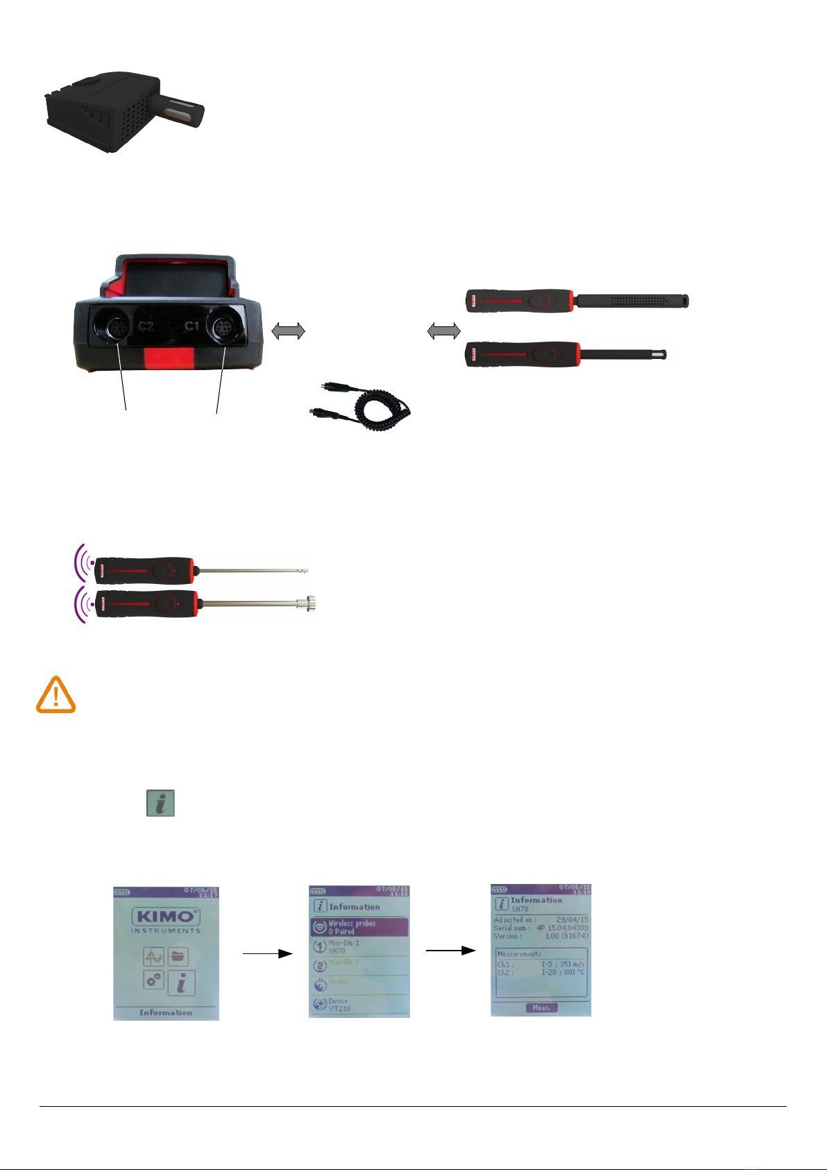
2.2 . Connections........................................................................................................................................................ 7
3. INFORMATION............................................................................................................................................................9
4. SET THE INSTRUMENT............................................................................................................................................... 10
4.1 . Set l ngu ge..................................................................................................................................................... 10
4.2 . Set d te nd time.............................................................................................................................................. 10
4.3 . Activ te or de ctiv te the beep key....................................................................................................................10
4.4 . Set uto-off....................................................................................................................................................... 10
4.5 . Set b cklight.....................................................................................................................................................11
4.6 . Set security........................................................................................................................................................11
4.7 . Set code............................................................................................................................................................11
4.8 . Set printing.......................................................................................................................................................11
5. SET THE PROBES....................................................................................................................................................... 12
5.1 . Use of the wire probes nd modules..................................................................................................................12
5.2 . Speci l prec utions for ir velocity probes..........................................................................................................12
5.3 . Use of wireless probes......................................................................................................................................13
6. CHANNEL CONFIGURATION......................................................................................................................................14
6.1 . In irow mode.................................................................................................................................................14
6.2 . Delt T.............................................................................................................................................................. 15
7. START AND RECORD DATASETS.................................................................................................................................16
7.1 . St rt nd record d t sets...................................................................................................................................16
7.1.1 M nu l d t set..........................................................................................................................................16
7.1.2 Autom tic d t set...................................................................................................................................... 16
7.1.3 View the recorded d t sets.........................................................................................................................17
7.2 . L unch nd s ve ver ges.................................................................................................................................17
7.2.1 Point/Point ver ge.....................................................................................................................................17
7.2.2 Autom tic ver ge......................................................................................................................................18
7.2.3 Autom tic Point/Point ver ge....................................................................................................................18
7.3 . Hold-Min./M x..................................................................................................................................................19
8. SETTING OF MEASUREMENT PARAMETERS...............................................................................................................20
8.1 . Thermocouple module........................................................................................................................................20
8.1.1 Unit........................................................................................................................................................... 20
8.1.2 Type...........................................................................................................................................................20
8.1.3 Al rm.........................................................................................................................................................20
8.2 . Clim tic conditions module................................................................................................................................20
8.2.1 Unit........................................................................................................................................................... 20
8.2.2 Al rm.........................................................................................................................................................20
8.3 . V ne probe nd hotwire probe...........................................................................................................................21
8.3.1 Unit........................................................................................................................................................... 21
8.3.2 Integr tion.................................................................................................................................................21
8.3.3 Al rm.........................................................................................................................................................21
8.3.4 Norm tive v lue.........................................................................................................................................21
8.3.5 Atmospheric pressure.................................................................................................................................21
8.4 . Hygrometry probes............................................................................................................................................22
8.4.1 Unit........................................................................................................................................................... 22
8.4.2 Al rm.........................................................................................................................................................22
8.4.3 Atmospheric pressure.................................................................................................................................22
8.5 . T chometry........................................................................................................................................................ 22
8.5.1 Unit........................................................................................................................................................... 22
8.5.2 Type...........................................................................................................................................................22
8.6 . Multifunction probe...........................................................................................................................................22
8.6.1 Unit........................................................................................................................................................... 22
8.6.2 Atmospheric pressure.................................................................................................................................23
8.6.3 Integr tion.................................................................................................................................................23
8.6.4 Norm tive v lues........................................................................................................................................23
4
1. PRESENTATION
1.1 Instrument description
1.2 Key description
➢Left key: llows to n vig te from left to right
➢Right key: llows to n vig te from right to left
➢Up key: increments v lue or level
➢Down key: decrements v lue or level
➢OK key: v lid tes n ction
➢Es key: c ncels the ction or b cks to previous step
1.3 Remove battery
PRESENTATION
5
Fun tion keys
On/Off button
ESC button
Conguration menu
Measurement menu Dataset menu
Information menu
Home s reen
Navigation arrows
OK button
Battery level
Date and time
➢Turn off the instrument.
➢Turn it over.
➢Press the red button while sliding down the b ttery.
1.4 Directive 2014/53/EU
Hereby, S uerm nn Industrie SAS decl res th t the r dio equipment type VT 210 is in compli nce with Directive
2014/53/EU. The full text of the EU decl r tion of conformity is v il ble t the following internet ddress:
www.s uerm nngroup.com
6
PRESENTATION
2. CONNECTIONS OF THE VT 210
2.1 ain features
•S reen
120 x 160 pixels gr phic displ y nd b cklight. Displ y of 6 me surements, 3 simult neously. Size 50 x 67 mm.
•Printer (available as option)
The p per of the instrument is therm l p per with 10-ye r gu r ntee. It h s n e sy repl cement system of the p per
(E sylo d). In ddition, printing is f st.
•Battery
Rech rge ble Li-ion b ttery inside the instrument, 16 h b ttery-life with pressure module or 14 h hotwire probe. The
instrument is supplied with 5 V, 1 A power d pter to lo d the intern l b ttery. The current lo ding is indic ted by
b ttery symbol on the top left of the screen. The or nge led on the bottom of the instrument is lso on until the full lo ding
of the b ttery (the led turns green).
2.2 Conne tions
Inter hangeable modules
The interch nge ble modules h ve the SMART-2014 system nd re utom tic lly recognized once the connection is m de
on the instrument.
•Thermo ouple module:
CONNECTIONS OF THE VT 210
7
Light indic tor for
b ttery ch rging
USB connection
+ power supply
C2 mini-DIN
connection
Battery
Module Loc tion to
remove the
module
Probe h ndle
C1 mini-DIN
connection
Allows to me sure temper ture on Tc1, Tc2, Tc3 nd Tc4 ch nnels with wired
thermocouples K, J, T or S probes ended with m le mini ture connector
•Climati onditions module:
•Wire probes with SMART-2014 system
Wire probes with SMART 2014 system re utom tic lly recognized when connected to the instrument.
•Wireless probe / instrument ommuni ation
Wireless communic tion between probe nd instrument with utom tic recognition fter power-up.
Wireless probes shall be lo ated near the instrument for initial re ognition. Conne tion between VT
210 and wireless probes must be established.
3. INFORMATION
“Information” menu llows to view inform tion bout the instrument, probes nd module connected to the
“Wireless probe”, “Mini-DIN 1”, “Mini-DIN 2” or “Module” connections. To enter in this menu from home screen,
select the “Information” menu with the rrow keys then press OK.
8
INFORMATION
C2 mini-DIN
connection
C1 mini-DIN
connection
Probes re connected
on min-DIN
connectors C1 nd
/ or C2 (excepted
thermocouple probes)
Overmolded mini-DIN connector
with foolproong system. C ble
length lg. 450 mm, extension
2.4 m.
Allows to me sure hygrometry, mbient temper ture nd tmospheric pressure.
Available information for probes and module is:
•Type of probes nd module
•D te of the l st c libr tion or djustment
•Seri l number
•Firmw re version
•Me suring r nge
Available information for the instrument is:
•Type of instrument
•Seri l number
•Firmw re version
➢The function key “Measurement” llows to ccess directly to the “Measurement” menu.
INFORMATION
9
4. SET THE INSTRUMENT
The instrument is on.
➢With the rrow keys, go to “Conguration” menu.
➢Press OK.
4.1 Set language
“Conguration” screen is displ yed.
➢Select “Language” with the rrow keys then press OK.
Av il ble l ngu ges re displ yed.
➢Press Up nd Down rrows to select the required l ngu ge: FRA, ENG...
➢Press OK.
4.2 Set date and time
“Conguration” screen is displ yed.
➢Select “Date/time” with the rrow keys then press OK.
The screen of congur tion for d te nd time is displ yed.
➢Go to the “Date” form t with rrow keys then press OK.
➢Select: DD/MM/YYYY, MM/DD/YYYY or YYYY/MM/DD then press OK.
➢Go to the d y then press OK.
➢With Up nd Down keys, set the rst digit of the d y then go to the following one with right
rrow.
➢Press OK to v lid te.
Perform the s me procedure to set the month nd ye r.
➢Go the “Time” form t with rrow keys then press OK.
➢Select the time form t: “12H” or “4H” then press OK.
If “12H” is selected, it is possible to choose between “AM” for nte meridiem or “PM” for post meridiem.
➢Press OK, select “AM” or “PM” then press OK to v lid te.
➢Go the time then press OK.
➢With Up nd Down keys set the rst digit of the d y then go to the following one with right rrow.
➢Press OK to v lid te.
Perform the s me procedure to set minutes nd seconds.
➢Press function key “Validate” to le ve the screen nd to s ve modic tions or press Es to c ncel.
4.3 Activate or deactivate the beep key
“Conguration” screen is displ yed.
➢Select “Key beep” with rrow keys.
➢Press OK to ctiv te or de ctiv te the beep key.
The box is ticked if the beep is ctiv ted nd unticked when the beep is de ctiv ted.
4.4 Set auto-off
The uto-off function turns off the instrument fter moment of unused.
It is possible to set the uto-off of the instrument t 15 / 30 / 45 / 60 / 75 / 90 / 105 or 120 minutes or
to de ctiv te it.
“Conguration” screen is displ yed.
➢Select “Auto-off” with rrow keys then press OK.
➢Select the required dur tion or OFF to de ctiv te it with Up nd Down keys.
➢Press OK to v lid te.
10
SET THE INSTRUMENT
4.5 Set backlight
“Conguration” screen is displ yed.
➢Select “B cklight” with rrow keys then press OK.
➢Select the b cklight level between 1 and 9 or “Auto” with Up nd Down keys.
➢Press OK to v lid te.
4.6 Set security
This p rt llows to ctiv te or de ctiv te security code. This code will be sked when st rting the
instrument.
“Conguration” screen is displ yed.
➢Select “Se urity” with rrow keys.
➢Press OK to ctiv te or de ctiv ted the security.
If the security is ctiv ted, ple se cre te security code.
4.7
Set ode
If the security is ctiv ted, the selected code will be sked when st rting the instrument.
“Conguration” screen is displ yed nd the security is ctiv ted.
➢Go to “Code” then press OK.
➢With rrow keys, set e ch digit then press OK when the l st digit is set.
Modic tions re v lid ted, the instrument b cks to “Conguration” screen.
4.8 Set printing
“Conguration” screen is displ yed.
➢Select “Printing” with rrow keys then press OK.
➢Go to “Format” then press OK.
➢Select the ticket form t: long or short then press OK.
Long ti ket format: prints the me surement results + he der (oper tor n me, d te nd
time of the intervention, type of instrument nd its seri l number)
Short ti ket format: prints only the me surement results nd the seri l number of the
instrument
➢Go to “Logo” then press OK to ctiv te or de ctiv te it.
The box is ticked when the logo is ctiv ted nd unticked when the logo is de ctiv ted.
➢Go to “Operator” to enter n oper tor n me then press OK.
Keyp d is displ yed on the bottom of the screen.
➢Select the letters with rrow keys then press OK.
To go from the lower c se keyp d to the upper c se keyp d then to the numeric keyp d: press the function key:
To delete letter press the function key “Delete”.
➢Press the function key “V lid te” to v lid te the n me.
➢Go to “Header 1” to enter the he der n me then press OK.
Keyp d is displ yed on the bottom of the screen.
➢Select the letters with rrow keys then press OK.
➢Press the function key “Validate” to v lid te the he der 1.
➢Perform the s me procedure to enter n me for the “Header 2”, “Header 3” nd “Header 4”.
➢Press ESC to b ck to the “Conguration” screen nd to v lid te the modic tions.
SET THE INSTRUMENT
11
5. SET THE PROBES
5.1 Use of the wire probes and modules
•Conne t a probe
➢Connect the mini-DIN c ble on the mini-DIN connection of the probe.
➢Connect the mini-DIN c ble with the probe on the instrument.
A beep indic tes th t the oper tion h s been correctly performed.
➢Go to “Measurement” menu from the home screen.
➢Press OK
Measurement are displayed.
5.2 Special precautions for air velocity probes
12
SET THE PROBES
Probe onne tion Instrument onne tion
Arrow in front of
the user
Arrow in front of the
user
Bottom of the standard probe
Airflow direction
landmark
Protective tube of the
sensitive element (1)
Sensitive element (velocity)
Sensitive element
(temperature)
Bottom of the telescopic probe
Before any use of the devi e with an air velo ity probe, please lower the prote tive tube (1) of
the sensitive element (ex ept vane probe).
Always use the standard air velo ity probe with the red point in front of the ow.
Always use the teles opi probe with the white point in front of the ow.
5.3
Use of wireless probes
•Add a wireless probe
OR
SET THE PROBES
13
With rrow keys, go to
“Information” menu
then press OK.
In “Information” menu go to
“Wireless probe” then press
OK.
On the bottom of the
screen press the
function key “Create”.
Turn on the wireless probe
nd keep it press until the
light blinks
P iring is in progress
The probe inform tion is displ yed With the
function key “Meas.” It is possible to b ck to the
me surement screen. It is lso possible to delete
the wireless probe pressing the function key
“Delete”.
With rrow keys, go to
“Measurements”
menu then press OK.
In “Measurement” menu,
press the function key
“Channels”.
Press the function key
“Probes”.
With the rrow keys, select
“Add wireless probe...”
then press OK.
On the bottom of the screen
press the function key
“Create”.
Turn on the wireless probe nd
keep it press until the light
blinks
P iring is in progress
The probe inform tion is
displ yed With the function
key “Meas.” It is possible to
b ck to the me surement
screen. It is lso possible to
delete the wireless probe
pressing the function key
“Delete”.
6. CHANNEL CONFIGURATION
The ch nnel congur tion llows to modify the displ ying of the me sured p r meters.
The instrument is on.
➢With the rrow keys, go to “Measurement”.
➢Press OK.
➢Press the function key “Channels”.
The different functions of the probe re displ yed.
It is possible from the “Channels” menu to dd or delete some me surements.
➢Press the function key “Delete” in order to delete the selected me surement.
➢Press the function key “Add” to displ y the selected me surement.
➢Press “Add” to dd me surement on the screen (the def ult me surement displ yed on the screen re the
prim ry me surements).
It is possible from the “Channels” menu to choose the displ ying order of the me surement on the screen.
➢With rrow keys, select the me surement to modify nd press OK.
➢Go to the line “Channel num.” then press OK.
➢Select the ch nnel number nd press OK.
6.1 In airow mode
Airow:
In the “ hannels” menu:
➢Select with rrow key the sub-menu “Airow” then press OK.
➢Select “Channel num.” nd press OK.
➢Select ch nnel number nd press OK.
➢Go to the line “Type” then press OK.
➢Select the required type: “Re t”, “Cir ” or “K fa tor” nd press OK*.
➢If Re t is selected, go to the line “Re t” then select its dimension: 100x100, 200x200, 300x300, 400x400,
500x500, 600x600, 700x700, 800x800, 900x900 nd 1000x1000 mm. Press OK to v lid te.
OR
➢If Cir . is selected, go to the line “Diam”, then select its dimension : 100, 200, 300, 400, 500, 600, 700, 800, 900
nd1000 mm .
➢Go to the line “Areas” then press OK.
It is possible to ch nge units nd size.
➢Select “Unit” with the rrow keys then press OK. Select mm or in nd press OK.
➢To modify re s, select with rrow keys “Re t.” or “Cir .” nd press OK.
➢Select the size to modify in the list nd press OK.
➢Set the size with rrow keys between 1 and 2500 mm then press OK.
➢Press ESC to b ck to the “Airow” menu.
➢Go to “d/p elem.” to select the differenti l pressure element then press OK.
➢Select the element between “Pitot L” (coefcient: 1.0015), “Pitot S” (coefcient: 0.84), “Debimo”
(coefcient: 0.8165) nd “Other”
➢Go to the line “K2 fa t.” nd press OK to select or unselect the K2 f ctor.
K2 f ctor is coefcient which is pplied to correct the ow r te only for the rect ngul r or circul r surf ces.
➢To select “Cone”, go to the line “Cone” then press OK.
➢Select the type of cone: K35, K75, K120 or K150 nd press OK.
14
CHANNEL CONFIGURATION
➢Press “Measures” to displ y the me surements.
6.2 Delta T
Delt T is function which llows to dene temper ture difference c lcul ted between two temper ture ch nnels of the
s me type.
➢Connect the thermocouple module then the probes.
In the “Channels” menu:
➢Select with rrow keys the sub-menu “Delta T” then press OK.
➢Select “Channel number” nd press OK.
➢Select ch nnel number nd press OK.
➢Select the ch nnels in which Delt T will be c lcul ted.
➢Go to “Channel A” with rrow keys nd press OK.
➢Select the ch nnel T1, T2, T3 or T4 nd press OK.
➢Go to “Channel B” with rrow keys nd press OK.
➢Select the ch nnel T1, T2, T3 or T4 nd press OK.
➢Press the key “Measurement”.
The instrument displ ys the me surements.
CHANNEL CONFIGURATION
15
7. START AND RECORD DATASETS
The instrument in on.
➢Select with rrows keys “Measurement” menu.
➢Press OK.
➢Select with rrows keys the me surement in which the d t set will be performed.
➢Press “Fun tions” key then select “Dataset” with rrow keys nd press OK.
D t set menu is displ yed.
➢Go to line “Name” with rrow keys nd press OK.
A keyp d is displ yed on the bottom of the screen.
➢Select the letters with rrow keys then press OK.
To go from the lower c se keyp d to the upper c se keyp d then to the numeric keyp d:
➢
press the function key:
To delete letter press the function key “Delete”.
➢Press the function “V lid te” to v lid te the n me of the d t set.
➢
➢A d t set is composed of sever l d ted me suring points. You c n choose between n
utom tic d t set or m nu l d t set.
➢Go to “Type” with rrow keys then press OK.
➢Select “Manu.” for m nu l or “Auto.” for utom tic.
Go to “Start” then press OK.
7.1 Start and record datasets
7.1.1 Manual dataset
A manual dataset is composed of me suring points selected by the oper tor.
M nu l mode is selected, me surements re displ yed.
➢Press OK to v lid te me suring point.
➢Press OK s m ny time s the required number of points.
➢Press the function key “Save”.
The instrument displ ys the me suring d t set: type of d t set, number of points, d te, minimum, m ximum,
ver ge nd st nd rd devi tion.
The d t set is utom tic lly recorded.
➢Press OK to displ y the gr ph of the results.
➢Press the function key “Zoom+” to displ y the det il of the c lcul ted points.
➢Press Es key to b ck to the d t set screen.
➢Press the function key “Print” to print the d t set.
Printing mode is displ yed.
➢Go to the line “Channels info” nd press OK to print the ch nnels on the printing ticket.
➢Go to the line “Details” nd press OK to print det ils of the d t set on the printing ticket.
➢Press the function key “Validate” to print.
The instrument b cks to the d t set displ y.
➢Press Es to b ck to “measurement” menu.
7.1.2 Automatic dataset
An automati dataset is composed of me suring points with interv l of time.
Autom tic mode is selected, me surements re displ yed.
➢Press the function key “Duration” to set the d t set dur tion.
➢Press OK on the line “Duration”.
16
START AND RECORD DATASETS
➢Go to “Hour” with the rrow keys then press OK, set the dur tion with rrow keys then press OK.
➢Perform the s me procedure for the minutes nd seconds.
➢Press the function key “Validate” when the dur tion is set.
➢Press OK on the line “Interval”.
➢Go to “min” with the rrow keys then press OK, set the dur tion with rrow keys then press OK.
➢Perform the s me procedure for the seconds.
➢Press the function key “Validate” when the interv l is set.
➢Press Es to b ck to me suring d t set.
➢Press the function key “Start” to l unch the me suring d t set.
The countdown st rts.
➢It is possible to stop the me suring d t set by pressing the function key “Stop”.
➢Press “Start” to rest rt the d t set.
➢Press “Duration” to modify the dur tion.
➢
Press “Save” to s ve the d t set.
The instrument displ ys the me suring d t set: type of d t set, number of points, d te, minimum, m ximum,
ver ge nd st nd rd devi tion.
The d t set is utom tic lly recorded.
➢Press OK to displ y the gr ph of the results.
➢Press the function key “Zoom+” to displ y the det il of the c lcul ted points.
➢Press Es key to b ck to the d t set screen.
➢Press the function key “Print” to print the d t set.
Printing mode is displ yed.
➢Go to the line “Channels info” nd press OK to print the ch nnels on the printing ticket.
➢Go to the line “Details” nd press OK to print det ils of the d t set on the printing ticket.
➢Press the function key “Validate” to print.
The instrument b cks to the d t set displ y.
Press Es to b ck to “Measurement” menu.
7.1.3 View the recorded datasets
➢Go to the “Dataset” menu with the rrow keys from the home screen.
The different me suring d t sets re displ yed. They re listed by d te.
➢To delete ll the d t sets: press the function key “Del all”.
➢To delete just one d t set: go to the d t set to delete with the rrow keys nd press the function key “Delete”.
➢A conrm tion window opens: select YES to conrm the deletion or NO to c ncel.
7.2 Launch and save averages
The instrument is on.
➢Go to “Measurement” with the rrow keys.
➢Press OK.
➢Press the function key “Fun tions” then select “Averages” then press OK.
“Average” menu is displ yed.
7.2.1 Point/Point average
This function llows to c lcul te the ver ge v lue of v rious points th t you c n select.
➢Go to “Point/Point” line in the “Averages” menu nd press OK.
➢Press OK to dd me suring points.
The instrument displ ys the type of d t set, number of points, d te, minimum, m ximum,
ver ge nd st nd rd devi tion.
➢Press the function key “Details” to get det ils for e ch point.
➢Press the function key “Save” to s ve the Point/Point ver ge.
START AND RECORD DATASETS
17
A keyp d is displ yed on the bottom of the screen.
➢Select the letters with rrow keys then press OK.
To go from the lower c se keyp d to the upper c se keyp d then to the numeric keyp d: press the function key:
To delete letter press the function key “Delete”.
➢Press the function key “Validate” to v lid te the n me.
The rec p of the Point/Point ver ge is displ yed.
➢Press OK to displ y the gr ph.
➢Press the function key “Zoom+” to displ y the det il of the c lcul ted points.
➢Press Es key to b ck to the d t set screen.
➢Press the function key “Print” to print the d t set.
Printing mode is displ yed.
➢Go to the line “Channels info” nd press OK to print the ch nnels on the printing ticket.
➢Go to the line “Details” nd press OK to print det ils of the d t set on the printing ticket.
➢Press the function key “Validate” to print.
The instrument b cks to the Point/point ver ge displ y.
➢Press Es to b ck to “Measurement” menu.
7.2.2 Automatic average
This function llows to c lcul te n ver ge v lue th t the device me sured in n interv l chosen
time.
➢Go to “Automati ” line in the “Averages” menu nd press OK.
➢Press the function key “Start” to st rt the me surement.
Dur tion is displ yed.
➢Press the function key “Stop” to stop the me surements.
Me surements, ver ge, minimum nd m ximum v lues, st nd rd devi tion nd dur tion
re displ yed.
➢Press the function key “Start” to l unch new utom tic ver ge.
➢Press the function key “Save” to s ve the results.
A keyp d is displ yed on the bottom of the screen.
➢Select the letters with rrow keys then press OK.
To go from the lower c se keyp d to the upper c se keyp d then to the numeric keyp d:
➢
press the function key:
To delete letter press the function key “Delete”.
➢Press the function key “Validate” to v lid te the n me.
The rec p of the utom tic ver ge is displ yed..
➢Press OK to displ y the gr ph.
➢Press the function key “Zoom+” to displ y the det il of the c lcul ted points.
➢Press Es key to b ck to the d t set screen.
➢Press the function key “Print” to print the d t set.
Printing mode is displ yed.
➢Go to the line “Channels info” nd press OK to print the ch nnels on the printing ticket.
➢Go to the line “Details” nd press OK to print det ils of the d t set on the printing ticket.
➢Press the function key “Validate” to print.
The instrument b cks to the utom tic ver ge displ y.
➢Press Es to b ck to “Measurement” menu.
7.2.3 Automatic Point/Point average
This function llows to c lcul te the ver ge v lue of v rious points, c lcul ted themselves on
dur tion beforeh nd dened.
➢Go to “Auto Pt/Pt” line in the “Averages” menu nd press OK.
A dur tion is displ yed on the bottom right of the screen.
18
START AND RECORD DATASETS
➢Press the function key “Duration” to modify the dur tion if necess ry.
➢Go to “min” with the rrow keys then press OK, set the dur tion with rrow keys then press OK.
➢Perform the s me procedure for the seconds.
➢Press the function key “Validate” when the interv l is set.
➢Press OK to st rt the me surement.
A the end of the me suring d t set, me surements, ver ge, minimum nd m ximum
v lues, st nd rd devi tion nd dur tion re displ yed.
➢Press OK to dd new me suring point to the c lcul tion.
The countdown st rts.
➢Press the function key “Details” to get det ils of the results.
➢Press the function key “Save” to s ve the results of the utom tic ver ge.
A keyp d is displ yed on the bottom of the screen.
➢Select the letters with rrow keys then press OK.
To go from the lower c se keyp d to the upper c se keyp d then to the numeric keyp d: press the function key:
To delete letter press the function key “Delete”.
➢Press the function key “Validate” to v lid te the n me.
The rec p of the d t set is displ yed.
➢Press OK to displ y the gr ph.
➢Press the function key “Zoom+” to displ y the det il of the c lcul ted points.
➢Press Es key to b ck to the d t set screen.
➢Press the function key “Print” to print the d t set.
Printing mode is displ yed.
➢Go to the line “Channels info” nd press OK to print the ch nnels on the printing ticket.
➢Go to the line “Details” nd press OK to print det ils of the d t set on the printing ticket.
➢Press the function key “Validate” to print.
The instrument b cks to the utom tic point/point ver ge displ y.
➢Press Es to b ck to “Measurement” menu.
7.3 Hold- in./ ax.
➢Go to “Measurement” menu with the rrow keys nd press OK.
Me surements re displ yed.
➢Press OK.
Me surements re frozen on the screen nd the minimum nd m ximum v lues re displ yed.
START AND RECORD DATASETS
19
8. SETTING OF MEASUREMENT PARAMETERS
The instrument is on.
➢Go to “Measurement” menu with the rrow keys nd press OK.
➢Select the me surement to set with the rrow keys.
➢Press the function key “Params”.
The different p r meters re displ yed.
➢For ll probes nd modules, it is possible to modify the ch nnel number.
➢Select “Channels” with the rrow keys nd press OK.
➢Select “Channel num.” nd press OK.
Select ch nnel number for the p r meter, nd press OK. This number denes the order displ y
of the p r meters.
8.1 Thermocouple module
8.1.1 Unit
➢Go to the line “Temperature” nd press OK.
➢Select the required unit: °C or °F
➢Press OK to v lid te the unit selection.
8.1.2 T pe
➢Go to the line “Type T ” nd press OK.«».
➢Select the type of thermocouple: K, T, J nd S
➢Press OK to v lid te.
8.1.3 Alarm
➢Go to the line “Temp.alarm” nd press OK.
➢Select “High alarm” nd/or “Low alarm” by pressing OK.
It is possible to set the high nd low thresholds.
➢Go to the line “High threshold” nd press OK.
➢Set the threshold with the rrow keys between -9999.9 nd 9999.9°C then press OK.
➢Go to the line “Low threshold” nd press OK.
➢Set the threshold with the rrow keys between -9999.9 nd 9999.9°C then press OK.
8.2 Climatic conditions module
8.2.1 Unit
Temper ture:
➢Go to the line “Temperature” nd press OK.
➢Select the required unit: °C or °F
➢Press OK to v lid te the unit selection.
8.2.2 Alarm
Temper ture:
➢Go to the line “Temp.alarm” nd press OK.
➢Select “High alarm” nd/or “Low alarm” by pressing OK.
It is possible to set the high nd low thresholds.
➢Go to the line “High threshold” nd press OK.
➢Set the threshold with the rrow keys between -9999.9 nd 9999.9°C then press OK.
20
SETTING OF MEASUREMENT PARAMETERS

Other sauermann Thermometer manuals

sauermann Si-TT3 User manual

sauermann

sauermann Si-TT3 User manual

sauermann KIRAY 50 User manual

sauermann

sauermann KIRAY 50 User manual

sauermann KIMO TM 210 User manual

sauermann

sauermann KIMO TM 210 User manual

sauermann KIRAY 100 User manual

sauermann

sauermann KIRAY 100 User manual

sauermann KIRAY 200 User manual

sauermann

sauermann KIRAY 200 User manual

sauermann Si-TI3 User manual

sauermann

sauermann Si-TI3 User manual

sauermann TK 61 User manual

sauermann

sauermann TK 61 User manual

sauermann KIRAY 300 User manual

sauermann

sauermann KIRAY 300 User manual

Popular Thermometer manuals by other brands

UEi 550B quick guide

UEi

UEi 550B quick guide

YaliTech eti quick start guide

YaliTech

YaliTech eti quick start guide

CAPTELEC T 1390 quick start guide

CAPTELEC

CAPTELEC T 1390 quick start guide

NUK 10.256.380 Operating instructions & user manual

NUK

NUK 10.256.380 Operating instructions & user manual

Braun IRT 4520 manual

Braun

Braun IRT 4520 manual

Sealey VS900.V2 instructions

Sealey

Sealey VS900.V2 instructions

Mobi Technologies PRIME instruction manual

Mobi Technologies

Mobi Technologies PRIME instruction manual

Microlife MT 550 manual

Microlife

Microlife MT 550 manual

Brannan DT-8835 user manual

Brannan

Brannan DT-8835 user manual

Maverick ET-8 instruction manual

Maverick

Maverick ET-8 instruction manual

Citizen CTD 505 instruction manual

Citizen

Citizen CTD 505 instruction manual

Broil King 61935 quick start guide

Broil King

Broil King 61935 quick start guide

iTD Temp Guardian HTG quick start guide

iTD

iTD Temp Guardian HTG quick start guide

Omega Engineering HH64A operating instructions

Omega Engineering

Omega Engineering HH64A operating instructions

Philips AVENT SCH740 manual

Philips

Philips AVENT SCH740 manual

Reer 9850 Instructions for use

Reer

Reer 9850 Instructions for use

ALDI V4916DSO364 user manual

ALDI

ALDI V4916DSO364 user manual

G&C GrillEye Detailed user guide

G&C

G&C GrillEye Detailed user guide

manuals.online logo
manuals.online logoBrands
  • About & Mission
  • Contact us
  • Privacy Policy
  • Terms and Conditions

Copyright 2025 Manuals.Online. All Rights Reserved.