4
WATER HEATER INSTALLATION
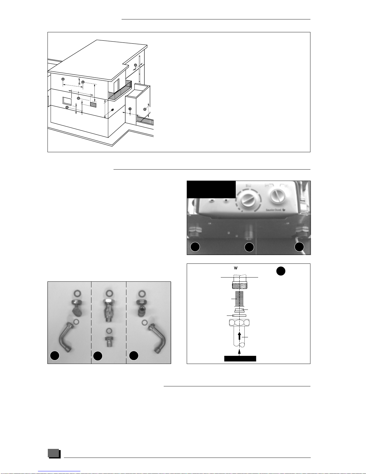
LOCATION
When determining the siting of the water heater,
make sure you keep an approx. distance of 50 mm
between the sides of the appliance to ensure total
accessibility for servicing.
The jig will enable you to determine the position of
the flue system hole at the top outlet. All informa-
tion regarding the installation of the flue system is
provided in the flue system package.
If the water-heater is not fitted straight away, the
water and gas fittings must be protected from
contaminents E.G. plaster, paint.
PIPE FITTINGS : Gas Manual gas cock 3/4" F - 1/2" M
Cold water inlet : stop cock 3/4" F - 1/2 " M with
angled tail
DHW outlet : 3/4" F - 1/2 " M angled tail
This appliance must be installed in accordance with
the current issue of :
●The gas safety (installation and use) regulations
●The building regulations
●The local water company byelaws
●The building standards regulations (Scotland)
●The health and safety at work act.
The gas safety (installation and use) regulations : it is
the law that all gas appliances are installed by
competent persons in accordance with the above
regulations. Failure to install appliances correctly
could lead to prosecution. It is in your own interest,
and that of safety, to ensure the law is complied
with.
TECHNICAL DATA
Refer to the data badge for exact type of appliance
and the gases it is suitable for.
Variable output of 8,7 kW (29665 Btu/h)
to 22,7 kW (77403 Btu/h)
Efficiency 78,4 %
Minimum flow rate, hot water temperature to :
maxi. position 2,7 l/min (0,60 g/min)
mini. position 4,2 l/min (0,92 g/min)
Maximum flow rate (by flow limiter) 3 l/min (2,86 g/min)
Specific flow rate (∆t 30 °C) 11 l/min (2,42 g/min)
Minimum water pressure [pw] 0,3 bar (4,50 Ib/in2)
Maximum water pressure*[pw] 10 bar (150 Ib/in2)
Max hot water temperature 60 °C
Venting of flue gases via flue system Ø 60 mm
Incoming fresh air via flue system Ø 100 mm
Supply voltage 230 V
Current 0,31 A
Power 55 W
Electrical protection IP 44
* These maximum water pressure values take into account
the dilation of the water.
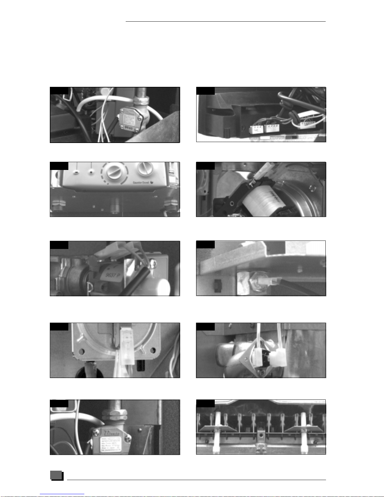
Only a qualified technician is authorized to intervene on
sealed mechanisms.
Gas Category : II
2H3+
.
Ø buner injector 1,20 mm
Appliance Inlet pressure 20 mbar
Max. gas flow rate output 2,75 m3/h
Min. gas flow rate 1,13 m3/h
Natural (G 20) (ref. 15
°
C and 1013 mbar)
Ø buner injector 0,80 mm
Appliance Inlet pressure 28 - 30 mbar
Max. gas flow rate output 2,04 kg/h
Min. gas flow rate 0,83 kg/h
Butane (G 30)
Ø buner injector 0,80 mm
Appliance Inlet pressure 37mbar
Max. gas flow rate output 2,02 m3/h
Min. gas flow rate 0,82 m3/h
Propane (G 31)
Car 019
100 100
141 141
445,2 316,4
61,6
17
17
19,5
EFEC GAZ
86
103
AC GAS AF
134
50
mini
245 mini
100 100
141 141
445,2 316,4
61,6
1717
19,5
EFEC GAZ
100 mm 100 mm
316,4 mm
3%


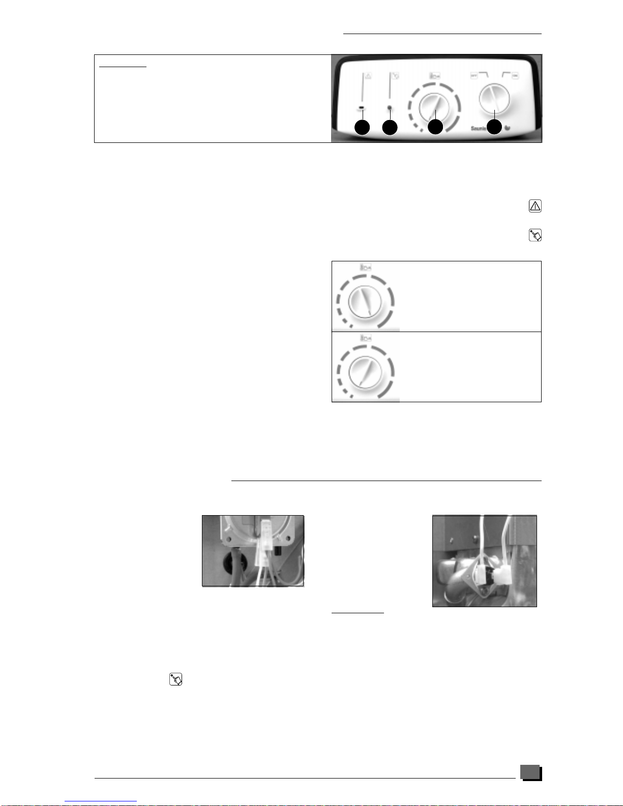
 Operation and maintenance instructions")