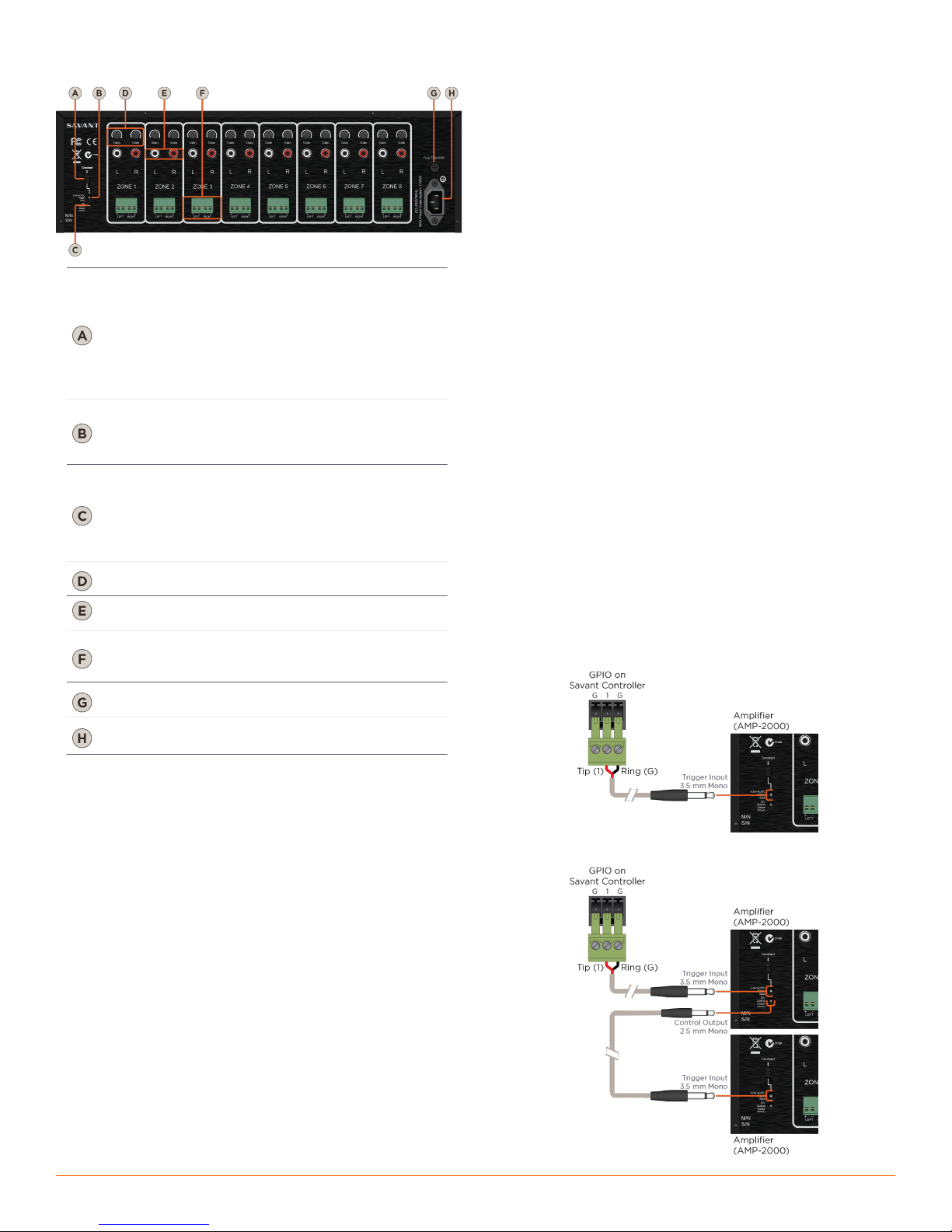
Rear Panel
Provides three options for turning the
AMP-2000 On and Off.
• Constant (manual turn-on via the front panel
master Power button)
• Audio Sense
• 3-24 AC/DC Voltage Trigger (External)
See Setting the Amplifiers Turn On Mode for
details.
3-24V AC/DC
Voltage
Trigger
3-24V AC/DC - 3.5 mm (1/8”) Mono jack
Used to control the power state of the amplifier
when Turn-on Mode switch is set to 3-24 AC/
DC Voltage Trigger mode.
12V Trigger
Control
Output
12V DC 100mA - 2.5 mm (3/32”) Mono jack
Used to trigger an additional AMP-2000 or
other device that is activated by receiving a 12V
DC 100mA signal. This voltage is present only
when the amplifier is active or on.
See External Trigger Connections for details
Independent gain controls allowing for fine-
tuning the output level of each channel.
RCA Stereo (L&R) line-level analog audio
inputs.
4-pin Screw Down Plug-in Connectors
Note: Specify 4 or 8 ohm speakers when
designing the system.
IEC 320 power connector with 3-pole
detachable power cord.
T15AH/250V (120V) (N. America)
T8AL/250V (230V) (International)
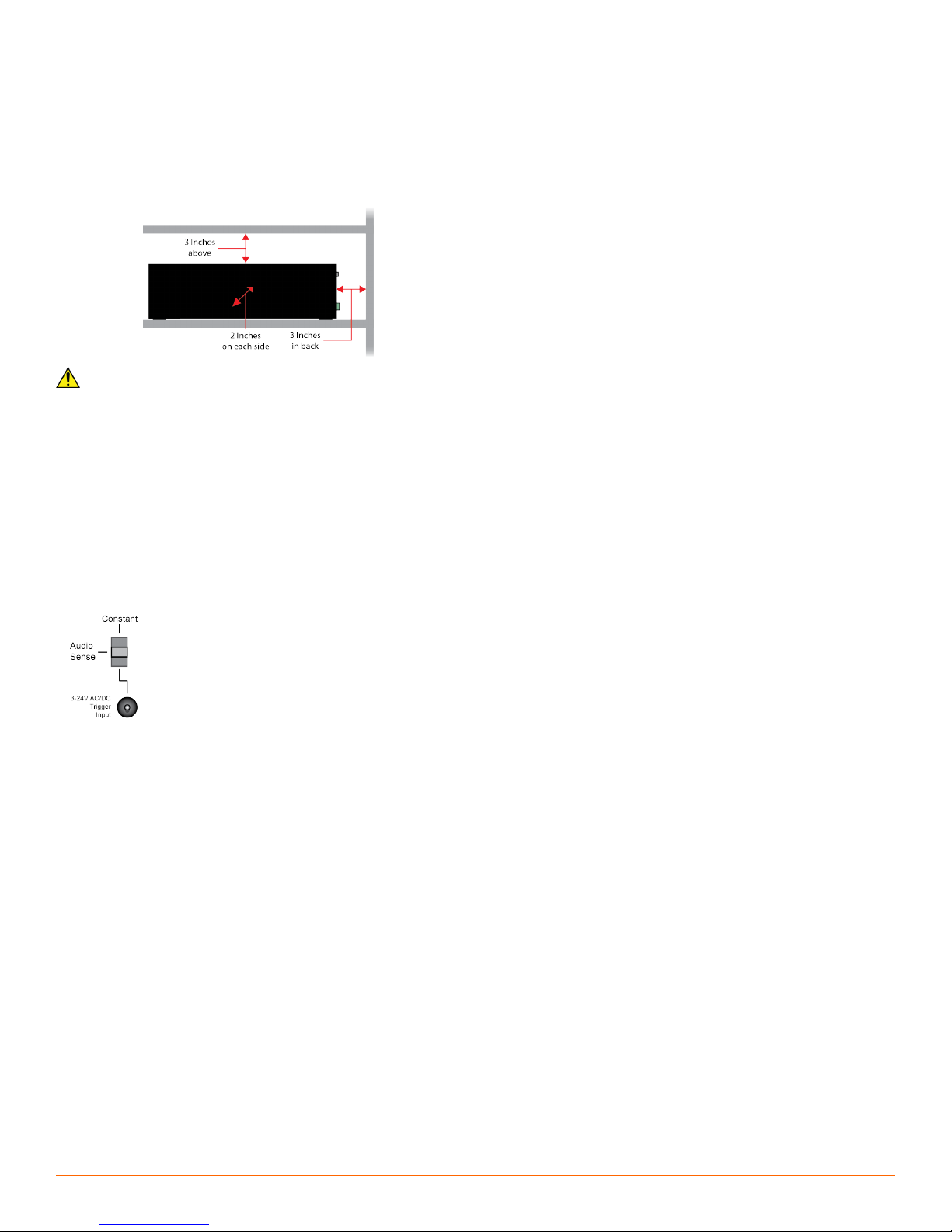
Installation
The AMP-2000 should be placed on a solid flat surface such as a table
or shelf or in an audio/video equipment rack. It should be placed
upright so that its weight rests on the unit’s four feet (removable). See
Ventilation for information on providing adequate cooling to the
amplifier when placed in a cabinet.
Cabling and Wiring
The AMP-2000 has multiple connections on the back panel. Savant
recommends that you clearly label all the input cables and speaker
wires. Label the cables and wires with their destination or source,
rather than which terminal of the AMP-2000 they are connected to it
will be easier to reconfigure the system in the future.
Cabling Precautions
•The amplifier must be offwhenever you make changes to the input
connections.
•Never connect a source or preamplifier’s input to the inputs of the
AMP-2000 directly.
•All speaker wire connections must be made with the amplifier off.
•Do not allow a single strand of wire to touch the amplifier chassis
or another connector.
Source Audio Connections
The AMP-2000 connects to a Savant distributed audio solution via
shielded line level audio cables with RCA phonograph plugs. Use high
quality RCA cables to connect the audio sources to the amplifier
inputs.
Savant recommends labeling all of the cables as the sources they
connect to (for example, CD player, media server).
Speaker Wire Connections
The AMP-2000 connects to the speakers using 2-conductor speaker
wire. For most applications, Savant recommends using 16-gauge or 18-
gauge wire. For wiring runs longer than 80 feet, Savant recommends
using 14-gauge wire. Each channel features a removable screw
terminal speaker connection for easy installation in tight spaces. The
terminal connector can accommodate up to 14-gauge stranded
speaker wire.
Bare Speaker Wire
Split the speaker wire insulation so that at least two inches of each
conductor are separated. Strip 1/4 inch of insulation from the end of
each conductor of the speaker wire. Twist the strands of speaker wire
together and insert them into the appropriate screw terminal speaker
connection.
AC Power Plug Connection
The last connection made should be the AC power using a standard
IEC 3-pole detachable power cord. Plug the attached power plug into
a correctly grounded 120V/60 Hz (AMP-2000) or 240V/50 Hz
(AMP-2000I) wall outlet.
External Trigger Connections
CAUTION!
Do not use a DC wall adapter. The long discharge time of the DC adapter’s filter
capacitor will delay the turn-offof the amplifier.
Note:
The 3-24V AC/DC Voltage Trigger mode allows you to configure the amplifier to
turn on automatically.
Note:
When connecting the first AMP in the chain, the 3.5 mm jack connecter will need
to be cut off. Strip the cable’s outer jacket to expose the two leads. Connect as
shown in the diagrams below.
Savant GPIO External Trigger Connection
Daisy Chaining External Triggers
AMP-2000-00/AMP-2000I-00 | 009-0421-03 | 150327
AMP-2000-00/AMP-2000I-00 | 009-0421-03 | 150327
45 Perseverance Way, Hyannis, MA 02601
Copyright © 2015 Savant Systems, LLC
savant.com | 508.683.2500