Savant SST-W100 Quick reference guide

Contents
To access the link to the topics in this document, click the topic text or topic page.
Introduction 3
Deployment Steps 4
SST-W100 Overview 5
Thermostat Removal and Installation 7
Powering the Thermostat 8
Wiring Diagrams 9
Wi-Fi Installation and Maintenance 12
Set HVAC System Type 18
RacePoint Blueprint 19
Humidity 28
Temperature 32
User and Maintenance Settings 35
.......................................................................................................Main Thermostat Control Screen 35
.....................................................................................................................................................Set Clock 36
..............................................................................................................................................Filter Service 37
...............................................................................................................................Maintenance Service 37
........................................................................................................................................Screen Timeout 38
...........................................................................................................................Set Temperature Scale 38
.......................................................................................................................................BackLite Display 38
...............................................................................................................................................Display Lock 39
.............................................................................................................................................Service Mode 39
................................................................................................................................................Relay States 40
.......................................................................................................................Restore Default Settings 40
Configuration Examples 41
....................................Appendix A: Menu Selection Screen - Descriptions 43
.................................Appendix B: Installer Settings Screen - Descriptions 45
.............................................................Appendix C: Network Requirements 48
SST-W100 Wireless Thermostat Deployment Guide
Copyright © 2016 Savant Systems, LLC
009-0802-08 | 160225
2
of
50

1. Introduction
The SST-W100 is a programmable Wi-Fi® enabled thermostat that can be configured into a Savant Control
system to control a Heating, Ventilation, and Air Conditioning (HVAC) system. This deployment guide
describes the following:
•Overview of physical thermostat
•Specifications and Requirements tables
•Installation and Wiring
•Join a local Wi-Fi network
•Basic Setup (Examples)
•Wiring and Configuring Auxiliary Relays
•Configuration into RacePoint Blueprint®
Once the system is connected and controlling an HVAC system, it can then be configured to a user’s
specifications. Each menu on the LCD screen is described with example configurations. Utilize this
deployment guide to aid you in all aspects of installation and configuration of the SST-W100 thermostat.
Before You Begin
Read through this document in its entirety and ensure that the following required items are available:
.......................................................................................................................SST-W100 Thermostat with all hardware
.........................................................................................................................................Existing Savant Control system
.....................................................................................................................................................HVAC cables (if required)
.................................................................................................................Additional Temperature Sensors (Optional)
..............................................................................................................................Cat 5e/6/7 cables for wiring sensors
SST-W100 Wireless Thermostat Deployment Guide
Copyright © 2016 Savant Systems, LLC
009-0802-08 | 160225
3
of
50

2. Deployment Steps
Follow these steps to successfully deploy the SST-W100 Wi-Fi® thermostat. This page can be used as a
checklist to record which steps have been completed.
1. ........................................................................................................................Unpack and Verify all hardware
See SST-W100 Box Contents
2. ..............................................................................................................................Remove existing Thermostat
See Remove Existing Thermostat
3. ......................................................................................................................................................Install SST-W100
See Install Thermostat
4. .........................................................................................................................................................Connect Power
See Powering the Thermostat
5. .........................................................................................................................................................Connect HVAC
See Wiring Diagrams
6. ....................................................................................................................Configure the HVAC System Type
See Set HVAC System Type
7. .............................................................................................................................Configure Temperature Scale
See Set Temperature Scale
8. .........................................................................................................................................Connect to local Wi-Fi
See Connect to local Wi-Fi®
9. ................................................................................................................Configure into RacePoint Blueprint
See RacePoint Blueprint®
10. ............................................................................................................................Upload Configuration to Host
See Upload Configuration
11. ........................................................................................................Connect to User Interface (Savant App)
See Open User Interface (Savant App)
12. ..........................................................................................Connect to User Interface (TrueControl II App)
See Open User Interface (TrueControl)
13. ................................................................................................................................................................User Guide
SST-W100 Wireless Thermostat Deployment Guide
Copyright © 2016 Savant Systems, LLC
009-0802-08 | 160225
4
of
50

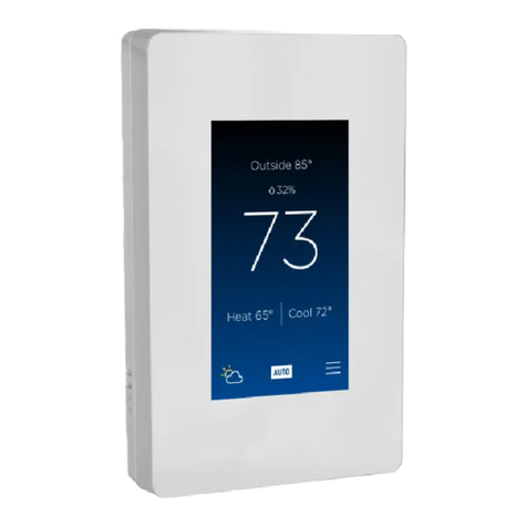
3. SST-W100 Overview
Components (Savant Control System)
Savant Host (Smart or Pro Host)
Wireless Network
Wired Network (Supplies voltage to power thermostat).
Optional Components
SST-TEMP1-xx - Remote Indoor Temperature Sensor
SST-OTEMP1-xx - Remote Outdoor Temperature Sensor
Front View
A
The Outside temperature displayed is retrieved from the remote sensor RS2 when configured as an outdoor
sensor.
B
Displays local time. The time is using the Set Clock menu.
C
State of functions/relays in thermostat. See table in Main Thermostat Control Screen section for more
information on the various states that can be displayed.
• Sys Off- Relays in thermostat for HVAC system are in Offstate. HVAC is not running.
• Fan Off- Fan relay is in Offstate. Fan is Off.
• Link OK - Connected to a local Wi-Fi network.
D
The temperature displayed is the local indoor temperature
E
Pressing the MENU button for the first time opens the SET CLOCK menu. Once the clock is set, pressing the
MENU button will open the thermostat control screen. Pressing the MENU button from the thermostat control
screen opens the Menu Selection screen.
F
The MODE button opens the following selections:
OFF - The thermostat will not communicate with an HVAC system.
HEATING - Only calls for heat are sent to the HVAC system.
COOLING - Only calls for cooling are sent to the HVAC system.
AUTO - Calls for both heating and cooling are sent to the HVAC system.
EHEAT - The EHEAT only appears when the thermostat is set to control a heat pump system. EHEAT is
typically used as a backup when failure to the compressor occurs.
G
The relative humidity data displayed is retrieved from a humidity sensor internal to the SST-W100.
H
The high and low setpoints are displayed. To increase or decrease the setpoints, press the up/down arrow
button to the right of each setpoint. Once in the heating or cooling setpoint screen, the temperature can be
raised or lowered.
I
The up/down arrow buttons are multipurpose buttons. In the screen shown, pressing the up or down arrow
button will open the high and low setpoint windows. In other windows, the buttons are used to move up and
down a list of items.
J
The FAN button opens the FAN MODE screen. From the FAN MODE screen the mode can be changed
between On and Auto. Select the correct mode for your HVAC system.
K
This button is used in the various menu screens for different functions.
SST-W100 Wireless Thermostat Deployment Guide
Copyright © 2016 Savant Systems, LLC
009-0802-08 | 160225
5
of
50

Rear View
A
Mounting Slots - The SST-W100 comes with wall anchors and screws to mount to an existing wall. Place the back
panel on the wall and mark where the wall anchors are to be installed.
B
Terminal Blocks - All wiring is connected to one of the two terminal blocks. Refer to table below for a brief
description of each position.
C
Wire Slot - This rectangular slot is where the wires coming from the HVAC system and/or remote sensors are fed
into the thermostat.
Terminal Block - Left
24RC
Connect the 24V AC hot wire from the
transformer on HVAC system to the
24RC terminal. When there is a separate
heating and cooling system, the wire
from the transformer on the cooling
system is wired here. **See Note below.
G
Connect to the fan terminal on the
HVAC system.
Y1
Connect to the 1st stage cooling
terminal on the HVAC system.
Alternately, connect to the 1st stage
compressor in a heat pump system
Y2
Connect to the 2nd stage cooling
terminal on the HVAC system.
Alternately, connect to the 2nd stage
compressor in a heat pump system
RS2
Connect to remote temperature sensor
RS2. No polarity is observed.
RS2
Connect to remote temperature sensor
RS2. No polarity is observed.
RSC
If there is a shield on the cable that
connects to remote sensor RS2,
connect that shield to the RSC terminal.
A1
• Auxiliary relay 1 can switch external
equipment such as a humidifier,
dehumidifier, and external vent
damper on and off.
• Auxiliary relay 1 can be turned on and
offaccording to workflows and
triggers set up in RacePoint Blueprint.
• Can control the speed of an external
dehumidification fan when an air
handler is used for dehumidification.
Terminal Block - Right
24C
Connect the common wire from the transformer
on HVAC system to the 24C terminal. When
there is a separate heating and cooling system
transformer, the common wire from the cooling
and heating system is wired here.
24RH
When there is a separate heating and cooling
system, the wire from the transformer on the
heating system is wired here. **See Note below.
W1
Connect to 1st stage heating terminal on the
HVAC system.
W2/0
Connect to 2nd stage heating terminal on the
HVAC system. If the system is a heat pump type
system, connect to the changeover terminal (O).
RS1
Connect to remote temperature sensor RS1. No
polarity is observed.
RS1
Connect to remote temperature sensor RS1. No
polarity is observed.
RSC
If there is a shield on the cable that connects to
remote sensor RS1, connect that shield to the
RSC terminal.
A2
• Auxiliary relay 2 can switch external
equipment such as a humidifier, dehumidifier
and external vent damper on and off.
•Auxiliary Relay 2 can be turned on and off
according to workflows and triggers set up in
RacePoint Blueprint.
**Note: When connecting power to the thermostat, if there are separate transformers for cooling and heating, the
transformer from the cooling system is wired to the 24RC terminal and the transformer from the heating system is wired
to 24RH terminal. In this scenario, jumper JP1 located on the PCB circuit board must be cut to separate the 24RH and
24RC terminals. Failure to cut this jumper could result is damage to the circuit board when powering the system. Refer to
the Powering the Thermostat section below.
SST-W100 Wireless Thermostat Deployment Guide
Copyright © 2016 Savant Systems, LLC
009-0802-08 | 160225
6
of
50

4. Thermostat Removal and Installation
Follow instructions below to remove or install the SST-W100 thermostat.
Remove Existing Thermostat
Follow the instructions below when removing an existing thermostat. Skip this section if an existing
thermostat is not being replaced.
1. Switch OFF power to the heating and cooling system either at the breaker panel or at the HVAC system
switch.
2. Open the old thermostat so the wiring is accessible. It is always good practice to take a picture of the
wiring before beginning the removal process.
3. Remove the wires from the old thermostat one by one. As each wire is removed, put a wire label on it
that matches the terminal designation on the old thermostat. The wire labels are supplied with each SST-
W100.
Note: Label the wires according to the old thermostat terminal designations. Do not label according to wire color.
4. Once all wires have been disconnected and labeled, remove old thermostat from wall.
Install Thermostat
The SST-W100 is to be mounted to an existing wall. When mounting, adhere to the following:
•Mount to an interior wall
•Avoid direct sunlight
•Do not mount behind a door and avoid corners when applicable
•Keep away from heating ducts or radiators.
•Keep away from appliances that produce radiant heat or cooling.
If replacing an existing thermostat, prior to removing, switch offpower to the heating and/or cooling system.
During the removal process, it is good practice to label each wire with the reference designator marked on
the thermostat being removed. Follow the instructions below to install the SST-W100 thermostat.
1. Separate the thermostat from its rear mounting plate by grasping the top and bottom of the rear
mounting plate in one hand and top and bottom of the thermostat in the other hand. Pull halves apart
by rocking the top and bottom of each half until they separate.
2. Position the rear mounting plate onto the wall where the thermostat will be located. Verify that writing
next to each 8-position terminal block can be read. If not, the rear panel is upside down.
3. With a pencil, mark the two slots in the rear mounting plate onto the wall.
4. Drill a ¼inch hole on each mark.
5. Insert the wall anchor into the holes drilled. Using a #2 screwdriver, rotate the wall anchor into the wall
using a gentle forward pressure until the anchor is flush with wall.
6. Place the thermostat base onto the wall. Pull the wires out through the center cutout located between
the two terminal blocks. Screw the rear mounting plate to the wall using the #6 x ¾inch self tapping
screws supplied.
SST-W100 Wireless Thermostat Deployment Guide
Copyright © 2016 Savant Systems, LLC
009-0802-08 | 160225
7
of
50

5. Powering the Thermostat
The SST-W100 requires 24V AC to power. The 24V AC can be supplied using one or two transformers. The
next few diagrams display the different power scenarios.
Input Voltage Range: 19V AC - 28V AC
One Transformer
If there is only one transformer powering the heating, cooling, or both, follow the diagram below.
One Transformer Scenario:
• Connect the hot side of the transformer to the
24RC terminal.
• Connect the common side of transformer to the
24C terminal.
• DO NOT cut jumper JP1. JP1 is located on the
bottom right section of the circuit board.
Additional Information:
To power the SST-W100, both a power wire and a
common wire is required. Some older systems do
not connect the common wire from the HVAC
system to the thermostat. In this scenario, a
separate common wire will need to be run.
Two Transformers
If there is a separate transformer powering the heating and cooling system, follow the diagram below.
Two Transformer Scenario:
• Cut jumper JP1 to separate the 24RH and 24RC
terminals. JP1 is located on the bottom right side
of the PCB.
• Connect the hot side of the transformer
powering the cooling system to the 24RC
terminal.
• Connect the hot side of the transformer
powering the heating system to the 24RH
terminal.
• Connect the common wire from the transformer
from the cooling system to the 24C terminal.
Additional Information:
To power the SST-W100, both a power wire and a
common wire is required. Some older systems do
not connect the common wire from the HVAC
system to the thermostat. In this scenario, a
separate common wire will need to be run.
Additional Information
•The 24RC terminal supplies power to the SST-W100 PCB board as well as to the Y1, Y2, and Grelays.
•The 24RH terminal supplies power to just the W1, W2, and Orelays.
Refer to the wiring diagrams in the Wiring Diagrams section below for more information on connecting
power as well as information on wiring the HVAC system to the thermostat.
SST-W100 Wireless Thermostat Deployment Guide
Copyright © 2016 Savant Systems, LLC
009-0802-08 | 160225
8
of
50

6. Wiring Diagrams
Below are a few wiring diagram examples to aid in the installation of the different types of HVAC systems.
Standard One Stage Heat
Additional Information:
The SST-W100 requires both the 24RC and 24C
terminals connected to power the thermostat. In
this scenario, a separate (C)ommon wire may need
to be added.
This system employs only one transformer so JP1
inside the thermostat should not be cut.
Standard One Stage Heat, One Stage Cool, Separate Fan Control
Additional Information:
The SST-W100 requires both the 24RC and 24C
terminals connected to power the thermostat. In
this scenario, a separate (C)ommon wire may need
to be added.
The system employs only one transformer so JP1
inside the thermostat should not be cut.
In this system there is a separate fan that can be
controlled either manually or through software on
the thermostat.
SST-W100 Wireless Thermostat Deployment Guide
Copyright © 2016 Savant Systems, LLC
009-0802-08 | 160225
9
of
50

Standard One Stage Heat, One Stage Cool, Separate Fan Control, Separate
Transformers
Additional Information:
The system employs two separate transformers.
Connect one transformer to 24RC and 2nd
transformer to 24RH. Jumper JP1 on circuit board
must be cut or damage to thermostat can occur.
The (C)ommon wire from each transformer is wired
to the 24C terminal.
In this system there is a separate fan that can be
controlled either manually or through software on
the thermostat.
Standard Two Stage Heat, Two Stage Cool, Separate Fan Control, Separate
Transformers
Additional Information:
The system employs two separate transformers.
Connect one transformer to 24RC and 2nd
transformer to 24RH.
The (C)ommon wire from each transformer is wired
to the 24C terminal.
Jumper JP1 on circuit board must be cut or
damage to thermostat can occur.
In this system there is a separate fan that can be
controlled either manually or through software on
the thermostat.
SST-W100 Wireless Thermostat Deployment Guide
Copyright © 2016 Savant Systems, LLC
009-0802-08 | 160225
10
of
50

Heat Pump One Stage Heat, One Stage Cool
Additional Information:
The SST-W100 requires both the 24RC and 24C
terminals connected to power the thermostat. In
this scenario, a separate (C)ommon wire may need
to be added.
The heat pump system employs only one
transformer so JP1 inside the thermostat should
not be cut.
HVAC systems employing a heat pump, use a
reversing valve to switch between heating and
cooling.
Heat Pump Two Stage Heat, Two Stage Cool
Additional Information:
The SST-W100 requires both the 24RC and 24C
terminals connected to power the thermostat. In
this scenario, a separate (C)ommon wire may need
to be added.
The heat pump system employs only one
transformer so JP1 inside the thermostat should
not be cut.
HVAC systems employing a heat pump, use a
reversing valve to switch between heating and
cooling.
SST-W100 Wireless Thermostat Deployment Guide
Copyright © 2016 Savant Systems, LLC
009-0802-08 | 160225
11
of
50

7. Wi-Fi Installation and Maintenance
After the system is wired, it can join a local Wi-Fi network. The following section describes how to join a local
network as well as a few maintenance functions that can be performed on the Wi-Fi radio.
Connect to local Wi-Fi®
1. From the Menu Selection screen, scroll to and Select the WiFi Setup field to open the WiFi Setup screen.
2. From this screen, there are a few methods available for connecting to a local wireless network. The next
few sections describe each method.
Passphrase Information
TIP! When entering the Shared ID (Passphrase) of the Wi-Fi network, the number and type
of characters supported on the SST-W100 are dependent on the firmware loaded.
Firmware = 2.13.00 and above
• Length = 63 ASCII characters
• Spaces = Allowed in Shared ID/Passphrase
• ASCII Characters = A-Z, a-z, 0-9
Firmware = Prior to 2.13.00
• Length = 27 ASCII characters
• Spaces = NOT allowed in Shared ID/Passphrase
• ASCII Characters = $NOT allowed. All other ASCII characters above are acceptable.
Restore Wi-Fi to Defaults
The Wi-Fi radio can be restored to its default settings. To do this follow the steps below.
1. From the main window setup screen, press the MENU button to open the Menu Selection screen.
2. Scroll to and Select the WiFi Setup option. This opens the WiFi Setup window.
3. Scroll to and Select the Restore Radio option. The radio will reset and open the WiFi Setup window.
4. Press the Done button to revert to the Menu Selection window.
5. Scroll to and Select the WiFi Network Status option. The window below displays the default settings.
Note: The port number that follows the IP: Address is not reset after the restore. The port remains as originally
configured.
SST-W100 Wireless Thermostat Deployment Guide
Copyright © 2016 Savant Systems, LLC
009-0802-08 | 160225
12
of
50

WPS Connect
WPS (Wi-Fi Protected Setup) or Simple Config is a fast and easy way of connecting the SST-W100 to a local
network when the SSID and Shared ID/Passphrase of the network is not known.
Before trying to connect the SST-W100 to the local network, the router has to be specifically configured for
WPS so the router supports the WPS/Simple Config method. To connect using the WPS Connect standard,
follow the steps below.
1. Enable the router in the local network to use the WPS/Simple Config standard and configure the WPS
standard to utilize the Push Button method.
2. On the router, push the WPS button to turn on the discovery of new devices. At this point the router will
start seeking a wireless client.
Note: Each router’s WPS setup is different. Refer to the router’s instructions on how setup and enable
the WPS standard.
3. Press the MENU button to open the Menu Selection window.
4. Scroll to and Select the WiFi Setup option. This opens the WiFi Setup window.
5. Scroll to and Select the WPS Connect option.
6. A WPS Connect Status window will open and display the connection status.
7. After a few seconds, the SST-W100 will connect to the network and a WPS Connection Successful
message is displayed. After a few seconds, the WiFi Network Status menu will open and display
pertinent information about the network where the thermostat is connected. Make note of the IP
Address of the thermostat as it will be used when connecting to the Savant Control system in later
sections of this document.
SST-W100 Wireless Thermostat Deployment Guide
Copyright © 2016 Savant Systems, LLC
009-0802-08 | 160225
13
of
50

Connect to SSID Network
The SST-W100 can connect to a network by either scanning the area looking for local networks or if known,
the SSID of the network can be entered so the thermostat scans for that network. Both processes are
described below.
Scan for Networks - (DHCP Enabled)
1. From the main window setup screen, press the MENU button to open the Menu Selection screen.
2. Scroll to and Select the WiFi Setup option. This opens the WiFi Setup window.
3. Scroll down the WiFi Setup screen and set the following fields using +/-buttons:
Selection
Action
DHCP
Set to Enabled (For this procedure, the thermostat will connect using the DHCP protocol.)
Security
Leave the Security setting as Open. The thermostat will automatically pull the security
protocol from the router. At any time after the SST-W100 has joined a local network, the
security protocol can be modified.
Chan
The default is set to Auto. Accept the default unless it needs to be set to a specific channel.
Use the +/-buttons to set the channel (Range 1-13).
Port
The default is port 2000. Accept the default unless a different port is required.
To modify the port number:
• Scroll to the Port option and press the Select button. The Edit Port window will open.
• Using the up/down arrows and left/right arrows, edit the Port number.
• Select Done when complete.
4. Scroll to and Select the SSID option. This will open the WiFi Networks window.
5. Scroll down the list to the local network. Press the Join button.
6. An Enter Passphrase screen will appear. Enter the Shared Key/Passphrase to the network the
thermostat will be joining.
Note: In the Enter Passphrase window, the up/down arrow buttons scroll through the ASCII characters
and the left/right arrow buttons move the cursor to the next or previous character. Refer to the
Passphrase Information tip above.
7. Select Done.
8. The SST-W100 will now connect to the network. When linked to the network, a box displaying
CONNECTED will appear and then open the Wifi Network Status window.
9. Verify the information in the WiFi Network Status window is correct. Make note of the IP Address. The IP
Address will be required when connecting to the Savant Control system.
SST-W100 Wireless Thermostat Deployment Guide
Copyright © 2016 Savant Systems, LLC
009-0802-08 | 160225
14
of
50

Scan for Networks - (DHCP Disabled)
1. Press the MENU button to open the Menu Selection screen.
2. Scroll to and Select the WiFi Setup option. This opens the WiFi Setup window.
3. Scroll down the WiFi Setup screen and set the following fields using +/-buttons:
Selection
Action
DHCP
Set to Disabled (For this procedure, the IP Address, etc. will need to be input manually.)
Security
Leave the Security setting as Open. The thermostat will automatically pull the security
protocol from the router. At any time after the SST-W100 has joined a local network, the
security protocol can be modified.
IP
Scroll down and Select the IP option. This will open the Edit IP Address field.
• Using the up/down arrows and left/right arrows, modify the IP Address.
• Select Done when complete.
SUB
Scroll down and Select the SUB option. This will open the Edit Subnet Mask field.
• Using the up/down arrows and left/right arrows, modify the Subnet Mask.
• Select Done when complete.
GW
Scroll down and Select the Edit Gateway option. This will open the Edit Gateway field.
• Using the up/down arrows and left/right arrows, modify the Gateway IP Address.
• Select Done when complete.
DNS
If there is a DNS server in the network, scroll down and Select the DNS option. This will
open the Edit DNS field.
• Using the up/down arrows and left/right arrows, enter the IP Address of the DNS server
• Select Done when complete.
Port
The default is port 2000. Accept the default unless a different port is required.
To modify the port number:
• Scroll to the Port option and press the Select button. The Edit Port window will open.
• Using the up/down arrows and left/right arrows, edit the port number.
• Select Done when complete.
Chan
The default is set to Auto. Accept the default unless it needs to be set to a specific channel.
Use the +/-buttons to set the channel (Range 1-13).
Adhoc Mode
• Accept the default as Disabled.
4. Scroll to and Select the SSID option. This will open the WiFi Networks window.
5. Scroll down the list of networks to the local network and press the Join button.
6. An Enter Passphrase screen will appear. Enter the Shared Key/Passphrase for the network you will be
joining.
Note: In the Enter Passphrase window, the up/down arrow buttons scroll through the ASCII characters
and the left/right arrow buttons move the cursor to the next or previous character. Refer to the
Passphrase Information tip above.
7. Select Done.
8. The SST-W100 will now connect to the network. When linked to the network, a box displaying
CONNECTED will appear and then open the Wifi Network Status window.
9. Verify the information in the WiFi Network Status window is correct. Make note of the IP Address. The IP
Address will be required when connecting to the Savant Control system.
SST-W100 Wireless Thermostat Deployment Guide
Copyright © 2016 Savant Systems, LLC
009-0802-08 | 160225
15
of
50

Connect to specific SSID Network
1. Press the MENU button to open the Menu Selection screen.
2. Scroll to and Select the WiFi Setup option. This opens the WiFi Setup window.
3. Scroll to the DHCP selection. Using the +/-buttons select either Enabled or Disabled.
•If Enabled is set, go to the Scan for Networks - (DHCP Enabled) section and use table to configure.
•If Disabled is set, go to the Scan for Networks - (DHCP Disabled) section and use table to configure.
4. Scroll to and Select the SSID option. This will open the WiFi Networks window.
5. To connect to a network not in the list, press the New button. This will open the Edit SSID window.
6. Using the up/down arrows and left/right arrows, enter the SSID of the local network.
7. Select Done when complete. The SSID entered will automatically populate itself into the SSID field of the
WiFi Setup screen.
8. Scroll to and Select the Key field. This will open the Enter Passphrase window.
9. Using the up/down arrows and left/right arrows, enter the Shared Key/Passphrase of the local network.
10. Select Done when complete.
11. The SST-W100 will now connect to the network. When linked to the network, a box displaying
CONNECTED will appear and then open the Wifi Network Status window.
12. Verify the information in the WiFi Network Status window is correct. Make note of the IP Address. The IP
Address will be required when connecting to the Savant Control system.
Adhoc Mode
Adhoc Mode on the SST-W100 is not supported within a Savant configuration/installation.
SST-W100 Wireless Thermostat Deployment Guide
Copyright © 2016 Savant Systems, LLC
009-0802-08 | 160225
16
of
50

Reboot the Wi-Fi® radio
After performing maintenance on the local network router, in some instances, the Wi-Fi radio may need to be
rebooted to reconnect to the local network. If the thermostat does not automatically reconnect, perform the
following steps to reboot the Wi-Fi radio.
1. Press the MENU button to open the Menu Selection screen.
2. Scroll down and Select the WiFi Setup option. This will open the WiFi Setup screen.
3. Scroll down and Select the Reboot Radio option. The Wi-Fi radio will reboot.
4. Verify there is communications between the thermostat and either the router or Savant Control system.
5. Select Done when complete.
Display the WiFi Network Status
To display information such as the IP Address of the thermostat and SSID of the network, the WiFi Network
Status screen can be used. Follow the steps below to view the WiFi Network Status screen.
1. Press the MENU button to open the Menu Selection screen.
2. Scroll to and Select the WiFi Network Status option. This will open the WiFi Network Status screen.
Review the information and verify all settings.
3. Select Done when complete.
SST-W100 Wireless Thermostat Deployment Guide
Copyright © 2016 Savant Systems, LLC
009-0802-08 | 160225
17
of
50

8. Set HVAC System Type
The type of HVAC system needs to be configured into the thermostat.
1. Press the MENU button to open the Menu Selection screen.
2. Scroll to and Select the Thermostat Info option. This will open the Thermostat Info screen.
3. The default HVAC System Type configured is Standard/Gas. Press Done if this is the HVAC System Type
in your system. If however the System Type is a heat pump, press the Setup button to open the
Mechanical Settings screen.
4. From the Mechanical Settings screen, configure the HVAC System Type and Fan Type fields. Use the
arrow buttons to scroll and the +/- buttons to modify the settings.
5. Press Done twice when HVAC System Type and Fan Type have been configured. This will return you to
the Menu Selection screen again.
SST-W100 Wireless Thermostat Deployment Guide
Copyright © 2016 Savant Systems, LLC
009-0802-08 | 160225
18
of
50

9. RacePoint Blueprint
For the SST-W100 to be able to communicate with the Savant Control system, it must first be configured into
RacePoint Blueprint and added to the existing Savant Control configuration on the host. Follow the steps
below to add the SST-W100 into Blueprint.
Note: The procedure below assumes that there is an existing Savant Control system configured and the Smart
Host or Pro Host and iOS device is already part of an existing configuration.
1. Open the existing RacePoint Blueprint configuration.
2. From menu bar, select RacePoint Blueprint > Preferences to open the RacePoint Blueprint Preferences
screen.
3. Select the Update UI Defaults tab. Verify the Enable HVAC screen population option is checked.
SST-W100 Wireless Thermostat Deployment Guide
Copyright © 2016 Savant Systems, LLC
009-0802-08 | 160225
19
of
50

Add SST-W100
1. From the RacePoint Blueprint tool bar, select the Show Library icon to open the Components library.
2. Enter SST-W100 into the search bar.
3. Drag the SST-W100 thermostat into either a Shared Equipment zone or a User zone. Enter a Unique
Name that describes the thermostat and select Create.
TIP! The type of zone the thermostat is placed in will determine the amount of flexibility
available when configuring where in the user interface the thermostat service is available.
See bullets below:
•User Zone - When the thermostat is placed in a User Zone, the thermostat service that gets
created can only be displayed in that zone/room of the Savant App/TrueControl II user interface.
•Shared Equipment - When the thermostat is placed in a Shared Equipment zone, the thermostat
service that gets created can be displayed in any zone/room of the Savant App/TrueControl II user
interface. This is configurable by checking or unchecking the zones under the Enabled in Zones
field of the Show: menu.
A
- Select Enabled in Zones from the Show: drop
down menu.
B
- Put a check in the zones where you would like the
Thermostat service to be displayed. The service
will be added to the list of services displayed in
each zone (Savant App or TrueControl II App).
4. Drag the thermostat into the layout window.
5. Repeat steps 2-4 and add additional thermostats as required.
Add Network Device: Optional
If a network device is not part of the existing configuration, it will need to be added
1. Open the Component library again. Select Network Device from the All Components drop-down menu.
2. Drag the Generic Network Switch into the Shared Equipment zone. Either accept the default or modify
the unique name to identify the network switch.
3. Select Create to create the device.
4. Drag the Network Device into the layout window. Close the Component library.
SST-W100 Wireless Thermostat Deployment Guide
Copyright © 2016 Savant Systems, LLC
009-0802-08 | 160225
20
of
50
Other manuals for SST-W100
3
Table of contents
Other Savant Thermostat manuals

Savant
Savant GE SST-W300 User manual

Savant
Savant SST-W100 User manual

Savant
Savant CLI-8000 User manual

Savant
Savant CLI-W210 User manual

Savant
Savant SST-W100 User manual

Savant
Savant CLI-W210 Quick reference guide

Savant
Savant SST-W100 User manual

Savant
Savant GE SST-W300 Quick reference guide

Savant
Savant CLI-W200 User manual

Savant
Savant CLI-W210 01 Series User manual
Popular Thermostat manuals by other brands

Cellar Cool
Cellar Cool CM TWIN H.E. owner's manual

Speedheat
Speedheat MCD5-1999-SH user manual

Pro 1 IAQ
Pro 1 IAQ true comfort iii t721 operating manual

Timeguard
Timeguard TRT035 Operating & installation instructions

Pro 1 IAQ
Pro 1 IAQ WW160W Wireless Wire installation manual

Nu-Heat
Nu-Heat HMYDV user guide