SawStop RT-PHFS User manual

OWNER’S MANUAL
STANDALONE ROUTER TABLE
MODEL RT-FS/RT-PHFS

Copyright SawStop, LLC
All Rights Reserved
Updates of this manual may be
available at www.sawstop.com
1st printing, January 2018
The Standalone Router Table Assembly shown on the front cover is the cast iron model
RT-FS. The Four-Post Router Lift with Lock, Downdraft Dust Collection Box for Router Lift,
Flip Stop for Router Fence and Single Vertical Feather Board for Router Tables are installed.
These are optional accessories that does not come included with your
Standalone Router Table. Your setup may look different.
SawStop, the SawStop blade logo, and the conguration of this product are either registered
trademarks or trademarks of SawStop, LLC. Software copyright by
SawStop, LLC. All rights reserved.

TO OUR CUSTOMERS
Thank you for purchasing the SawStop Standalone Router Table Assembly with Phenolic or
Cast Iron Table. We are condent you will be pleased with the quality and performance.
This manual tells you more about your Standalone Router Table Assembly with Phenolic or
Cast Iron Table and how to operate and maintain it. Please read the manual carefully. The
manual also includes our warranty and important safety information.
If you ever have any questions or comments, feel free to contact us at the address below.
SawStop, LLC
11555 SW Myslony Street | Tualatin, Oregon 97062 USA
Phone: (503) 570-3200
Fax: (503) 570-3303
Email: [email protected]
www.sawstop.com

HOW TO GET HELP
Missing Parts? Have Questions?
Our technical support team is standing by
M-F, 6:30am-5pm PST
to help with whatever you need.
503.582.9934
Give us a call at
SERVICE@SAWSTOP.COM
Email us at

TABLE OF CONTENTS
Product Specications.........................................................................
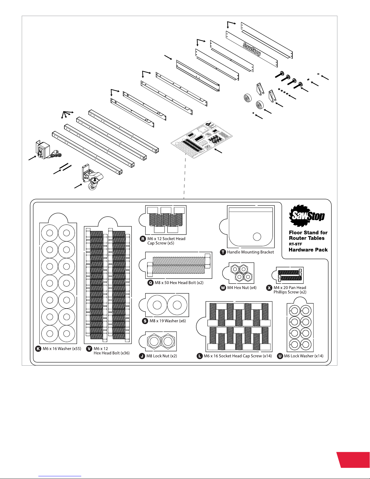
Parts Inventory.....................................................................................
Floor Stand (RT-STF)......................................................................................................
32" x 24" Cast Iron Router Table (RT-C32).....................................................................
32" x 24" Phenolic Router Table (RT-PH32)....................................................................
32" Fence Assembly (RT-F32).........................................................................................
Assembly Options................................................................................
Assembly and Installation.....................................................................
Assembling the Floor Stand ..........................................................................................
Assembling the Cast Iron Table......................................................................................
Installing the Cast Iron Table..........................................................................................
Assembling the Phenolic Table......................................................................................
Installing the Phenolic Table...........................................................................................
Assembling the Fence....................................................................................................
Reference............................................................................................
Warranty.........................................................................................................................
Safety.............................................................................................................................
Warnings........................................................................................................................
Exploded View 1: Floor Stand for Router Tables (RT-STF) ..............................................
Parts List 1: Floor Stand for Router Tables (RT-STF) .....................................................
Exploded View 2: 32" x 24" Cast Iron Router Table (RT-C32) ...........................................
Parts List 2: 32" x 24" Cast Iron Router Table (RT-C32) ...................................................
Exploded View 3: 32" x 24" Phenolic Router Table (RT-PH32) ........................................
Parts List 3: 32" x 24" Phenolic Router Table (RT-PH32) .................................................
Exploded View 4: 32" Fence Assembly for Router Tables (RT-F32) ...............................
Parts List 4: 32" Fence Assembly for Router Tables (RT-F32) .......................................
Available Accessories..........................................................................
1
3
3
5
6
7
9
11
11
17
19
20
22
23
30
30
31
31
33
34
35
36
37
38
39
40
41

1RT-FS/RT-PHFS OWNER’S MANUAL
PRODUCT SPECIFICATIONS
Floor Stand for Router Tables
Height Above Floor 34 ½" - 36 ½"
32" Fence Assembly for Router Tables
Length 35 ¾"
Height 3 ½"
Width 4"
32" x 24" Cast Iron Router Table
Cast Iron Table 32" x 24"
Maximum Fence Travel 5 ½"
Front T-slot to Arbor Center 6 ½"
Width of Front T-slot ½” at top,
3⁄8" at bottom
Rear T-slot to Arbor Center 5"
Width of Rear T-slot 1” at top,
¾" at bottom
32" x 24" Phenolic Router Table
Phenolic Table 32" x 24"
Maximum Fence Travel 30"
Front T-slot to Arbor Center 7"
Width of Front T-slot ½” at top,
3⁄8" at bottom
Rear T-slot to Arbor Center 5 ¾"
Width of Rear T-slot 1” at top,
¾" at bottom

2
RT-FS/RT-PHFS OWNER’S MANUAL
This page is intentionally blank.

3RT-FS/RT-PHFS OWNER’S MANUAL
PARTS INVENTORY PAGES:
3-8
IF YOU CANNOT FIND AN ITEM ON THIS LIST, CHECK THE MOUNTING
LOCATIONS OR EXAMINE THE PACKAGING MATERIALS VERY CAREFULLY.
CERTAIN COMPONENTS MAY HAVE BEEN PRE-INSTALLED FOR SHIPPING
PURPOSES.
Floor Stand for Router Tables (RT-STF)
Lower Front/Rear Bracket (2)
Lower Side Bracket (2)
Caster Mounting Bracket (1)
Upper Front/Rear Bracket (2)
Upper Side Bracket (2)
Stand Leg (4)
Floor Stand Switchbox Mounting
Bracket Assembly with Power Cord (1)
Caster Assembly with Table Bracket
Support Plate (1)
Leveling Foot (4)
Wheel Housing (2)
3" Wheel (2)
Pre-Installed:
M5 x 0.8 x 45 Pan Head
Phillips Screw (2)
M6 x 16 x 2 Washer (1)
M6 x 1.0 x 16 Socket Head
Cap Screw (1)
M10 x 1.5 Hex Nut (4)
M6 x 1.0 Hex Nut (1)
A.
B.
C.
D.
E.
F.
G.
I.
M.
O.
P.
H.
K.
L.
N.
Y.
Hardware Pack:
M8 x 1.25 Lock Nut (2)
M6 x 16 x 2 Washer (55)
M6 x 1.0 x 16 Socket Head
Cap Screw (14)
M8 x 1.25 x 50 Hex Head Bolt (2)
M6 x 1.0 x 12 Socket Head
Cap Screw (5)
M8 x 19 x 1.5 Washer (6)
Handle Mounting Bracket (1)
M6 Lock Washer (14)
M6 x 1.0 x 12 Hex Head Bolt (36)
M4 x 0.7 Hex Nut (4)
M4 x 0.7 x 20 Pan Head
Phillips Screw (2)
J.
K.
L.
Q.
R.
S.
T.
U.
V.
W.
X.
Some products are shipped partially assembled. Please unpack the parts carefully and
conrm you have received each item on the lists below.

4
RT-FS/RT-PHFS OWNER’S MANUAL
A
B
D
F
H
G
C
E
I
K
L
M
N
O
P
Y
HARDWARE PACK
You will also need the following tools to complete the Floor Stand Assembly:
• Phillips Head Screwdriver
• 8mm Wrench (x2)
• 10mm Wrench
• 13mm Wrench (x2)
See Exploded View #1 on page 33 for more information.
• 14mm Wrench
• 5mm Hex Wrench
• Level

5RT-FS/RT-PHFS OWNER’S MANUAL
32" x 24" Cast Iron Router Table (RT-C32)
32" x 24" Cast Iron Table (1)
M6 x 1.0 Hex Nut (10)
M6 x 1.0 x 40 Flat Head Phillips Screw (10)
A.
B.
C.
A
B
C
You will also need the following tools to complete the Cast Iron Router Table assembly:
• Phillips Head Screwdriver
See Exploded View #2 on page 35 for more information.

6
RT-FS/RT-PHFS OWNER’S MANUAL
32" x 24" Phenolic Router Table (RT-PH32)
A
B
C
32" x 24" Phenolic Router Table (1)
M6 x 1.0 Hex Nut (10)
M6 x 1.0 x 40 Flat Head Phillips Screw (10)
A.
B.
C.
You will also need the following tools to complete the Phenolic Router Table assembly:
• Phillips Head Screwdriver
See Exploded View #3 on page 37 for more information.

7RT-FS/RT-PHFS OWNER’S MANUAL
32" Fence Assembly for Router Tables (RT-F32)
32" Router Table Fence (1)
Fence Lock Knob (2)
M8 x 23 x 2 Washer (2)
23mm Wide Lock Knob Nut (2)
Fence Face Plate Lock Knob (8)
M6 x 16 x 2 Washer (14)
M6 x 1.0 x 35 T-Bolt (8)
2 ½" Dust Port (1)
1/4"-20 x 3/4" Pan Head Phillips Screw (2)
1/4"-20 Square Nut (8)
Face Plate Space Bar (2)
Router Fence Face Plate (2)
Router Fence Guard (1)
Router Fence Guard Spacer (2)
32" Table Rail with Ruler and Lock Knob (2)
Rail Mounting Bracket (2)
1/4" x 20 x 5/8" Hex Head Bolt (6)
M6 x 1.0 x 12 Socket Head Cap Screw (8)
19mm Wide Lock Knob Nut (2)
A.
B.
C.
D.
E.
F.
G.
H.
I.
J.
K.
L.
M.
N.
O.
P.
Q.
R.
S.
A
B
E
F
I
O
H
G
D
C
J
L
M
N
K
P
Q
R
S
You will also need the following tools to complete the 32" Fence Assembly:
• Phillips Head Screwdriver
• 10mm Wrench
See Exploded View #4 on page 39 for more information.
• 5mm Hex Wrench

8
RT-FS/RT-PHFS OWNER’S MANUAL
Throughout the manual, the exploded views are referenced to clarify the location and
name of each part. There are multiple exploded views in this manual, so a
decimal point system is used. The number before the decimal point refers to the
exploded view number (in this case, 1 through 4). The number after the decimal point
refers to the part number (as indicated by the number in the balloon in the exploded
view). For example, a part referenced as “1.1” would be the part labeled with a “1”
balloon in the exploded view #1.
• Exploded View #1: Floor Stand for Router Tables – See page 33
• Exploded View #2: 32" x 24" Cast Iron Router Table – See page 35
• Exploded View #3: 32" x 24" Phenolic Router Table – See page 37
• Exploded View #4: 32" Fence Assembly for Router Tables – See page 39
iImportant Part Identification Note:

9RT-FS/RT-PHFS OWNER’S MANUAL
ASSEMBLY OPTIONS PAGES:
9-10
32" x 24" Cast Iron Router Table Option 1 of 2
Either the 32" x 24" Cast Iron Router Table or the 32" x 24" Phenolic Router Table can be
mounted to your Floor Stand for Router Tables.
The 32" Fence Assembly for Router Tables can be installed on either table.
This huge cast iron table provides the
weight, stability and smoothness of cast
iron in a large, freestanding application.

10
RT-FS/RT-PHFS OWNER’S MANUAL
32" x 24" Phenolic Router Table Option 2 of 2
This huge phenolic table provides the
lightweight precision of phenolic surfaces
in a large, freestanding application.

11 RT-FS/RT-PHFS OWNER’S MANUAL
Requires: Floor Stand Components and Hardware
5mm Hex Wrench 14mm Wrench
8mm Wrench (x2) Phillips Head Screwdriver
10mm Wrench Level
13mm Wrench (x2) Floor Stand for Router Tables Hardware Pack
1
2
3
Remove the socket head cap screw (L),
washer (K) and hex nut (Y) at the top
of the caster assembly (I) as shown by
the blue arrows and set them aside for
a later step. Detach the table bracket
support plate (1.14) from the caster
assembly (I, comprised of 1.10-1.13,
1.15-1.19, 1.35-1.36) using a 5mm hex
wrench to remove the four socket head
cap screws (L) and washers (K) shown
by the red arrows – keep these for the
following step.
Attach the table bracket support plate
(1.14) to the caster mounting bracket (C)
and caster assembly (I) using the four
socket head cap screws (L) and four
washers (K) from the previous step
that were shown with red arrows.
Use a 5mm hex wrench to tighten
the screws. The cutouts in the caster
assembly should t over the bent edges
of the caster mounting bracket.
Thread the leveling foot (M) into the
bottom of a stand leg (F). Repeat this
process for the remaining three stand legs. x4
ASSEMBLY AND INSTALLATION PAGES:
11-29
Assembling the Floor Stand for Router Tables
L
C
1.14
1.14
L
F
M
K
K
K
I
I
L
Y

12
RT-FS/RT-PHFS OWNER’S MANUAL
5Refer to the hole pattern reference gure
from step 4 and align the mounting
holes in an upper side bracket (E) with
the mounting holes in the stand legs (F)
marked “aa,” align the mounting holes
in a lower side bracket (B) with the holes
marked “cc,” and align the mounting
holes in the caster mounting bracket
(C) with the holes marked “dd.” Mount
the brackets to the stand legs (F) using
twelve hex head bolts (V) and twelve
washers (K). Set this assembly aside.
4Place two stand legs (F) on a at
surface and position them so the top
surface of each tube and the outward-
facing surface of each tube have the
holes marked as “aa,” “bb,” “cc,” and
“dd” in the hole pattern reference gure.
Only nger tighten the hex head bolts during assembly of the oor stand. You will tighten all
the bolts after the stand is assembled.
i
The upper and lower side brackets are shorter than the upper and lower front/rear brackets.
Make sure you are using the correct brackets for each step.
i
6Attach the top of the table bracket support
plate (1.14) to the bent, bottom edge of the
lower side bracket (B) using the hardware
you saved from step 1 shown by the blue
arrows. Insert the socket head cap screw
(L) up through the holes in the table bracket
support plate (1.14) and lower side bracket (B)
and secure it with the washer (K) and the hex
nut (Y). Use a 5mm hex wrench and a 10 mm
wrench to tighten the nut.
aa
bb
cc
dd
ee
Hole Pattern
Reference
1.14
L
K
Y
B
E
B
C
F
V
K
F

13 RT-FS/RT-PHFS OWNER’S MANUAL
7
8
9
Place the other two stand legs (F) on
a at surface, and position them so
the top surface of each tube and the
outward-facing surface of each tube
have the holes marked as “aa,” “bb,”
“cc,” and “dd.”
Refer to the hole pattern reference
gure from step 7 and align the
mounting holes in the other upper side
bracket (E) with the stand leg (F) holes
marked “aa” and align the mounting
holes in the other lower side bracket
(B) with the holes marked “cc.” Mount
the brackets to the stand legs using
eight hex head bolts (V) and eight
washers (K).
Refer to the hole pattern reference
gure from step 7 and align the
mounting holes in the at edges of the
two wheel housings (O) with the bottom
two holes in the stand legs (F) marked
“dd.” Mount the wheel housings (O)
to the stand legs (F) using four socket
head cap screws (R) and four washers
(K). Use a 5mm hex wrench to tighten
the screws.
aa
bb
cc
dd
ee
Hole Pattern
Reference
E
F
F
B
O
R
F
K
V
K

14
RT-FS/RT-PHFS OWNER’S MANUAL
10
11
12
Next, mount the 3” wheels (P) to the
wheel housings (O). Insert a hex head
bolt (Q) through one side of a wheel
housing (O), then through a washer (S),
a 3” wheel (P), a third washer (S), the
other side of the wheel housing (O), and
another washer (S). Secure the bolt with
a lock nut (J). Use two 13mm wrenches
to tighten the nut, but do not over-
tighten the nut, or the wheel will not be
able to rotate. Repeat this process for
the other wheel assembly.
Rotate the stand legs (F) upright so
the leveling feet (M) are on the ground.
Refer to the hole pattern reference
gure from step 7 and align the
mounting holes in an upper front/rear
bracket (D) with the remaining top holes
in two stand legs (F) (marked as holes
“aa”) and align the mounting holes in
a lower front/rear bracket (A) with the
holes in the stand legs (F) marked “cc.”
Mount the brackets (D and A) to the two
stand legs (F) using eight hex head bolts
(V) and eight washers (K).
Repeat step 11 with the other upper
front/rear bracket (D) and lower front/
rear bracket (A), then use a 10mm
wrench to tighten all of the hex head
bolts (V) used to assemble the stand.
P
O
QS
S
J
D
D
V
V
K
A
F
M
A

15 RT-FS/RT-PHFS OWNER’S MANUAL
The switchbox assembly (G) can be installed on
either the front left or right stand leg (F). The handle
mounting bracket (T) can also be installed on
either stand leg (F).
13
14
Place a level on one of the upper
brackets and adjust the leveling feet (M)
to make sure the bracket is level. Check
the corners between the brackets and
the remaining three brackets, as shown
by the red arrows. Recheck all four
brackets, then use a 14 mm wrench to
tighten the hex nut (N) on each leveling
foot (M) up against the bottoms of the
stand legs (F). Make sure the feet are
adjusted so the wheels (P) just contact
the ground, but can still spin relatively
freely. If the wheels (P) are not close
enough to the ground, the stand will not
roll properly.
Insert a socket head cap screw (R) through a
washer (K), then through the square hole in
the handle mounting bracket (T). Then thread
the screw into one of the single holes in the
front of either front stand leg (F) (marked
as holes “bb” in the hole pattern reference
gure in step 7). Use a 5mm hex wrench
to tighten the screw. (The handle mounting
bracket (T) is adjustable and can be aligned
any way the user desires to hold the router
lift elevation handle.)
i
ROUTER LIFT
ELEVATION
HANDLE
N
R
T
F
K
P
F
M
M
T
G
F
This manual suits for next models
1
Table of contents
Other SawStop Indoor Furnishing manuals