SawStop TSA-SA70 User manual

OWNER’S MANUAL
LARGE SLIDING TABLE
MODEL TSA-SA70
Note: A typical assembly takes 5-10 hours.
Please set aside sufcient time to complete
the assembly process in 1-2 sessions.

The saw shown on the front cover is the Industrial Cabinet Saw, Model ICS.
Your saw may look different.
Copyright SawStop, LLC
All Rights Reserved
Updates of this manual may be
available at www.sawstop.com
3rd printing, August 2018
SawStop, the SawStop blade logo, and the conguration of this product are either
registered trademarks or trademarks of SawStop, LLC. Software copyright by
SawStop, LLC. All rights reserved.

TO OUR CUSTOMERS
Thank you for purchasing the SawStop Large Sliding Table. We are condent you will be
pleased with its quality and performance.
This manual tells you more about your large sliding table and how to operate and maintain
it. Please read the manual carefully. The manual also includes our warranty and important
safety information.
If you ever have any questions or comments, feel free to contact us at the address below.
SawStop, LLC
11555 SW Myslony Street | Tualatin, Oregon 97062 USA
Phone: (503) 570-3200
Fax: (503) 570-3303
Email: [email protected]
www.sawstop.com

HOW TO GET HELP
Missing Parts? Have Questions?
Our technical support team is standing by
M-F, 6:30am-5pm PST
to help with whatever you need.
503.582.9934
Give us a call at
SERVICE@SAWSTOP.COM
Email us at

TABLE OF CONTENTS
Product Specs.................................................................................
Parts Inventory.................................................................................
Parts & Hardware Lists.............................................................................................
Tools Needed...........................................................................................................
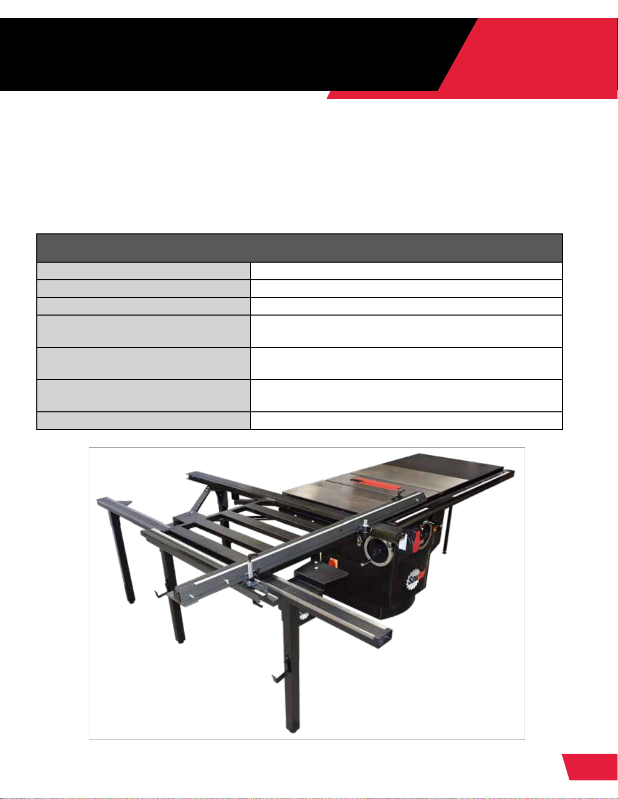
Getting to Know Your Large Sliding Table........................................
Components............................................................................................................
Mounting Options.....................................................................................................
Front Mounting WITHOUT Left Wing............................................................
Center Mounting WITHOUT Left Wing..........................................................
Rear Mounting WITHOUT Left Wing.............................................................
Front Mounting WITH Left Wing...................................................................
Center Mounting WITH Left Wing.................................................................
Rear Mounting WITH Left Wing....................................................................
Modifying Your Table Saw................................................................
Installing your Large Sliding Table...................................................
Shortening the Rails WITH the Extension Wing.......................................................
Shortening the Rails WITHOUT the Extension Wing...............................................
Assembling the Support Legs.................................................................................
Attaching the Mounting Bracket..............................................................................
Attaching the Positioning Plate................................................................................
Attaching the Inner Guide Tube...............................................................................
Installing the Sliding Table Support Assembly.........................................................
Installing the Lateral Brackets..................................................................................
Installing the Support Legs......................................................................................
Installing the Outer Guide Tube...............................................................................
Installing the Sliding Table & Sliding Table Stops....................................................
Adjusting the Sliding Table.......................................................................................
Adjusting the Ball Bearings............................................................................
Adjusting the Table Lock Handle...................................................................
Adjusting the Spacing....................................................................................
1
2
2
6
7
7
8
9
9
10
10
11
11
12
13
13
15
17
19
23
25
29
32
33
36
37
39
39
41
42

Installing the Guide Bearing Assembly....................................................................
Setting the Bearing Tension.....................................................................................
Installing the Angle Guide Rail.................................................................................
Installing the Crosscut Fence Assembly..................................................................
Traditional Conguration...............................................................................
Crosscut Fence Assembly Congurations...............................................................
Euro Conguration........................................................................................
Storage..........................................................................................................
Installing the Logo Plate...........................................................................................
Adjustments....................................................................................
Leveling....................................................................................................................
Installing the Remaining Support Leg......................................................................
Aligning to the Blade................................................................................................
Setting the Miter Angle Ruler (Traditional)..................................................................
Setting the Miter Angle Ruler (Euro)..........................................................................
Setting the Crosscut Fence Ruler............................................................................
Operations.......................................................................................
Reference........................................................................................
Warranty...................................................................................................................
Safety.......................................................................................................................
Warnings..................................................................................................................
Support System Exploded View..............................................................................
Support System Parts List.......................................................................................
Table Assembly Exploded View...............................................................................
Table Assembly Parts List........................................................................................
Crosscut Fence Exploded View...............................................................................
Crosscut Fence Parts List........................................................................................
44
47
51
54
54
60
60
65
66
67
67
70
72
77
80
82
85
87
87
88
88
90
91
94
95
96
97
TABLE OF CONTENTS

1
TSA-SA70 OWNER’S MANUAL
PRODUCT SPECIFICATIONS
Product Specications
Net Weight 173 lbs
Sliding Table Dimensions 30” x 30.75”
Maximum Table Travel 71.25”
Maximum Crosscutting Length 118” (On Professional Cabinet Saw without extension
wing)
Maximum Rip Capacity (Front Mount-
ing) 49”
Maximum Rip Capacity (Rear Mount-
ing) 70”
Weight Capacity Fully Extended 350 lbs
The SawStop Large Sliding Table is engineered for the demands of the Industrial
woodshop and ensures precise, repeatable operation. This Sliding Table makes cutting
sheet goods and larger stock easy, with maximum control and sure measurement. A rigid
steel frame and 14 sealed, steel bearings ensure a reliable, smooth glide, and adjustability
affords both traditional and Euro congurations for a maximum crosscut of 70”.

2TSA-SA70 OWNER’S MANUAL
PARTS INVENTORY
Parts and Hardware Lists
PAGES:
2-6
Inner Guide Tube (Qty. 1)
Outer Guide Tube (Qty. 1)
Crosscut Fence (Qty. 1)
Guide Rail (Qty. 1)
Mounting Bracket (Qty. 1)
A.
B.
C.
D.
E.
Parts Box (Labeled 2 of 2)
e
a
b
c
d
The Large Sliding Table is shipped partially assembled. Please unpack the parts carefully
and conrm you have received each item on both Parts Box lists and all Hardware bags.
If you cannot nd an item on the lists, check the mounting locations or examine the
packaging materials very carefully. Certain components may have been pre-installed for
shipping purposes.

3
TSA-SA70 OWNER’S MANUAL
Support Leg (Qty. 4)
Leg Bracket (Qty. 2)
Stepped Leg Bracket (Qty. 2)
Positioning Plate (Qty. 1)
Front Guide Bracket (Qty. 1)
Support Tube (Qty. 1)
Cross Brace (Qty. 3)
Sliding Table (Qty. 1)
Guide Bearing Assembly (Qty. 2)
Fence Pivot Assembly (Qty. 1)
Flip Stop (Qty. 1)
Miter Lock Assembly (Qty. 1)
Fence Extension (Qty. 1)
Logo Plate (Qty. 1)
F.
G.
H.
I.
J.
K.
L.
M.
N.
O.
P.
Q.
R.
S.
Parts Box (Labeled 1 of 2)
p
no
q
r
s
l
h
k m if
g
j

4TSA-SA70 OWNER’S MANUAL
Hardware Pack

5
TSA-SA70 OWNER’S MANUAL
M8 x 19 Washer (x4)
M8 x 5.5 Hex Nut (x4)
M8 x 16 Hex Head Bolt (x10)
M8 x 19 Washer (x10)
M8 x 16 Hex Head Bolt (x4)
M8 x 19 Washer (x4)
M4 x 12 Phillips Screw (x2)
Spacer (x2)
M4 x 10 Washer (x2)
M6 Lock Handle (x3)
T-nut (x1)
M6 x 25 Thumb Screw (x2)
M8 x 16 Shoulder Bolt (x2)
M8 x 16 Washer (x2)
M8 Hex Cap Nut (x2)
M8 x 50 Hex Head Bolt (x2)
M8 x 19 Washer (x2)
M8 x 30 Hex Head Bolt (x4)
M8 x 16 Washer (x8)
M8 Lock Nut (x4)
M8 x 12 Socket Head Cap Screw (x4)
M8 x 19 Washer (x4)
M8 x 16 Hex Head Bolt (x8)
M8 x 19 Washer (x8)
M5 x 20 Hex Head Bolt (x3)
M5 x 16 Washer (x3)
M5 Lock Nut (x3)
M8 x 16 Hex Head Bolt (x2)
M8 x 19 Washer (x2)
M8 x 50 Hex Head Bolt (x2)
M8 x 19 Washer (x4)
M8 Lock Nut (x2)
Self-tapping Screw (x2)
M5 x 16 Washer (x2)
M8 x 16 Shoulder Bolt (x12)
M8 Hex Cap Nut (x12)
M8 x 16 Washer (x12)
a.
b.
c.
d.
y.
z.
aa.
bb.
cc.
dd.
ee.
ff.
gg.
hh.
ii.
jj.
kk.
e.
f.
g.
h.
i.
j.
k.
l.
m.
n.
o.
p.
q.
r.
s.
t.
u.
v.
w.
x.
Pack 1: Assembling the Support Legs Pack 7: Installing the Outer Guide Tube
Pack 8: Installing the Sliding Table and
Sliding Table Stops
Pack 9: Installing the Angle Guide Rail
Pack 10: Installing the Crosscut
Fence Assembly
Pack 11: Installing the Logo Plate
Pack 12: Installing the Remaining
Support Leg
Pack 2: Attaching the Mounting Bracket
Pack 3: Attaching the Positioning Plate
Pack 4: Attaching the Inner Guide Tube
Pack 5: Installing the Support Assembly
Pack 6: Installing the Cross Braces/
Installing the Support Legs

6TSA-SA70 OWNER’S MANUAL
Tools Needed
•
•
•
•
•
•
•
•
•
•
•
•
•
•
•
•
•
•
•
Wrenches or combination wrenches
3/4” ratchet
Metal cutting band saw or hacksaw with metal
cutting blade
Rip fence or straight edge at least 30” long
Level
Square
Tape measure or calipers
Phillips head screwdriver
Needle nose pliers
Drill with Phillips bit
10mm wrench
10mm socket
5mm hex wrench
8mm wrench
3/4” socket
13mm wrench (x2)
12mm wrench
Small socket extension
Flashlight
Hardware Bag 1
Hardware Bag 2
6mm Hex T-wrench (x1)
5mm Hex T-wrench (x1)
Leveling Foot (x4)
Fence Storage Bracket (x2)
Frame Support Bracket (x1)
Cabinet Mounting Bracket (x1)
ll.
mm.
nn.
oo.
pp.
qq.
ll
pp
qq
mm
nn oo

7
TSA-SA70 OWNER’S MANUAL
GETTING TO KNOW YOUR LARGE
SLIDING TABLE
Components
PAGES:
7-11
Inner Guide Tube
Outer Guide Tube
Crosscut Fence
Guide Rail
Mounting Bracket
Support Leg
Leg Bracket
Stepped Leg Bracket
Positioning Plate
Front Guide Bracket
Support Tube
Cross Brace
Sliding Table
Fence Pivot Assembly
Flip Stop
Miter Lock Assembly
Fence Extension
Logo Plate
A.
B.
C.
D.
E.
F.
G.
H.
I.
J.
K.
L.
M.
O.
P.
Q.
R.
S.
A
B
H
J
C
QP
D
N
F
L
E I M
F
O
K
G
H
S

8TSA-SA70 OWNER’S MANUAL
Mounting Options
Fence Positions:
Capacities:
The SawStop Large Sliding Table can be mounted to your SawStop table saw in any of
six different table orientations and three fence positions.
TABLE ORIENTATION FENCE POSITION PCS ICS
Front Mount 90° Traditional 48.50” 49.50”
Front Mount 90° Euro 48.25” 48”
Front Mount WITH Left Wing 45° Traditional 55.25” 55.25”
Front Mount W/O Left Wing 45° Traditional 46.25” 47.75”
Center Mount 90° Traditional 37.50” 37.75”
Center Mount 90° Euro 59.25” 59”
Center Mount WITH Left Wing 45° Traditional 47.50” 47.50”
Center Mount W/O Left Wing 45° Traditional 38.50” 40”
Rear Mount 90° Traditional 26.50” 26.75”
Rear Mount 90° Euro 70.25” 70”
Rear Mount WITH Left Wing 45° Traditional 40” 40”
Rear Mount W/O Left Wing 45° Traditional 30.50” 32.25”
90° Euro:
Provides the Large
Sliding Table’s
maximum ripping
length by installing
crosscut fence at the
rear of the sliding table.
90° Traditional:
Positions the fence at
the front of the sliding
table.
45° Traditional:
Use traditional
mounting for
miter cuts.

9
TSA-SA70 OWNER’S MANUAL
Front Mounting WITHOUT Left Wing Option 1 of 6
Start on Page 15
Center Mounting WITHOUT Left Wing Option 2 of 6
Start on Page 15
This conguration provides
the maximum ripping length
with the crosscut fence in
the traditional conguration.
Since the left wing is not
installed, the crosscut table
is close to the saw blade.
90° Euro
Mounts
Forward of
Saw Cabinet
90° Traditional
45° Traditional
This conguration minimizes
the total footprint of the
table saw and crosscut table
and is the closest position
of the crosscut table to the
saw. The ripping length with
the crosscut fence in the
traditional conguration is
reduced from 49” to 37.5”.
90° Euro
Mounts
Center of
Saw Cabinet
90° Traditional
45° Traditional

10 TSA-SA70 OWNER’S MANUAL
Front Mounting WITH Left Wing Option 4 of 6
Start on Page 13
Rear Mounting WITHOUT Left Wing Option 3 of 6
Start on Page 15
This conguration provides
the maximum ripping length
with the crosscut fence in
the traditional conguration
while also maintaining the
additional support to the left
of the blade provided by the
left extension wing.
90° Euro
90° Traditional
45° Traditional
Mounts
Forward of
Saw Cabinet
This conguration provides
the maximum ripping length
with the crosscut fence in the
Euro conguration. Since the
left wing is not installed, the
crosscut table is close to
the blade.
90° Euro
Mounts
Rear of
Saw Cabinet
90° Traditional
45° Traditional

11
TSA-SA70 OWNER’S MANUAL
Center Mounting WITH Left Wing Option 5 of 6
Start on Page 13
Option 6 of 6
Start on Page 13
Rear Mounting WITH Left Wing
This conguration reduces
the front-to-back footprint
of the saw and crosscut
table while maintaining the
additional support to the left
of the blade provided by the
extension wing.
90° Euro
90° Traditional
45° Traditional
Mounts
Center of
Saw Cabinet
This conguration provides
the maximum ripping length
with the crosscut fence
in the Euro conguration
while also maintaining the
additional support to the left
of the blade provided by the
left extension wing.
90° Euro
90° Traditional
45° Traditional
Mounts
Rear of
Saw Cabinet

12 TSA-SA70 OWNER’S MANUAL
DISCONNECT YOUR TABLE SAW FROM ELECTRICAL POWER BEFORE
BEGINNING ANY MODIFICATIONS.
MODIFYING YOUR TABLE SAW
Before mounting the Large Sliding Table, you may need to modify your table saw.
Some of the steps below involve removing/installing your rails, switchbox, and extension
wing. For those steps, please refer to your table saw manual and fence manual. (You can
download copies of your manuals at www.sawstop.com.)
For Unassembled Saws: If your saw has not yet been assembled, you will rst need to
pre-install the rails to mark them for cutting.
• If you plan to mount the Large Sliding Table with the left extension wing, begin
by installing and aligning the left extension wing as described in the installation
documentation for your table saw.
• If you plan to mount the Large Sliding Table without the left extension wing, then do
not install the wing for this step.
• Next, install your rail assembly to the saw as described in your fence manual. It is not
necessary to install every screw or to fully align and tighten your rails at this time.
• Now proceed to page 13 if you plan to install the Large Sliding Table with the left
extension wing.
• Alternatively, proceed to page 15 if you plan to install the Large Sliding Table without
the left extension wing.

13
TSA-SA70 OWNER’S MANUAL
INSTALLING YOUR LARGE
SLIDING TABLE
Shortening the Rails WITH the Extension Wing
PAGES:
13-66
1
2
Mark the front rail and main tube 1 1/4” to the right of the left edge of the left
extension wing. If shortening the rear rail, mark the rear rail 1/4” to the right of the
left edge of the extension wing.
Use a 13mm wrench to remove the bolts from the underside of the main tube.
Set it aside.
3
4
Use a 13mm wrench and 5mm hex wrench to remove the front rail (and rear rail if
shortening rear rail).
Use a metal cutting band saw or a hack saw with a metal cutting blade to cut off
the front rail and main tube (and rear rail if shortening rear rail) at the marks made in
step 1.
USING OTHER TYPES OF SAWS (SUCH AS A CIRCULAR SAW) CAN
GENERATE ENOUGH HEAT TO BLISTER THE POWDER COATING. IT IS
STRONGLY SUGGESTED THAT YOU USE A METAL CUTTING BAND SAW
OR A HACK SAW WITH A METAL CUTTING BLADE ONLY.
WITH EXTENSION WING
Do You Need to Modify the FRONT Rails on Your Table Saw?
If you are installing your Large Sliding Table on a PCS model table saw, you will need to
shorten the front rails on your saw as described below.
However if you are installing your Large Sliding Table on an ICS model table saw, you only
need to shorten the front rails if they extend past the left edge of the left extension wing.
If you need to shorten the front rails, follow the steps described below. If you do not need
to shorten the front rails, you can skip to page 17.
Do You Need to Modify the REAR Rail on Your Table Saw?
If the left end of the rear rail does not extend past the left edge of the left extension wing,
then you do not need to shorten the rear rail. If you have not fully installed the rear rail,
complete the assembly of the rear rail as described in your fence manual.
If the left end of the rear rail does extend past the left edge of the left extension wing, then
you will need to shorten the rear rail as described below.

14 TSA-SA70 OWNER’S MANUAL
6Remove the plastic end cap from the cut off portion of the main tube and install it
on the new left end of the main tube.
7If necessary, complete the assembly of your saw then re-install the front and rear
rails and the main tube (refer to your saw and fence manuals).
When finished, continue to page 17.
WITH EXTENSION WING
5Remove any burrs or sharp edges with a le.
1 1⁄4”
Other manuals for TSA-SA70
1
Table of contents
Other SawStop Indoor Furnishing manuals