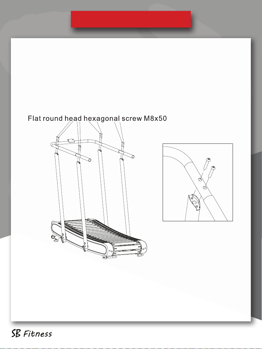
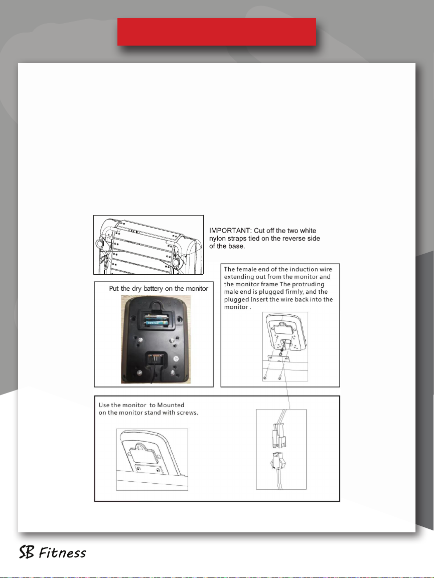
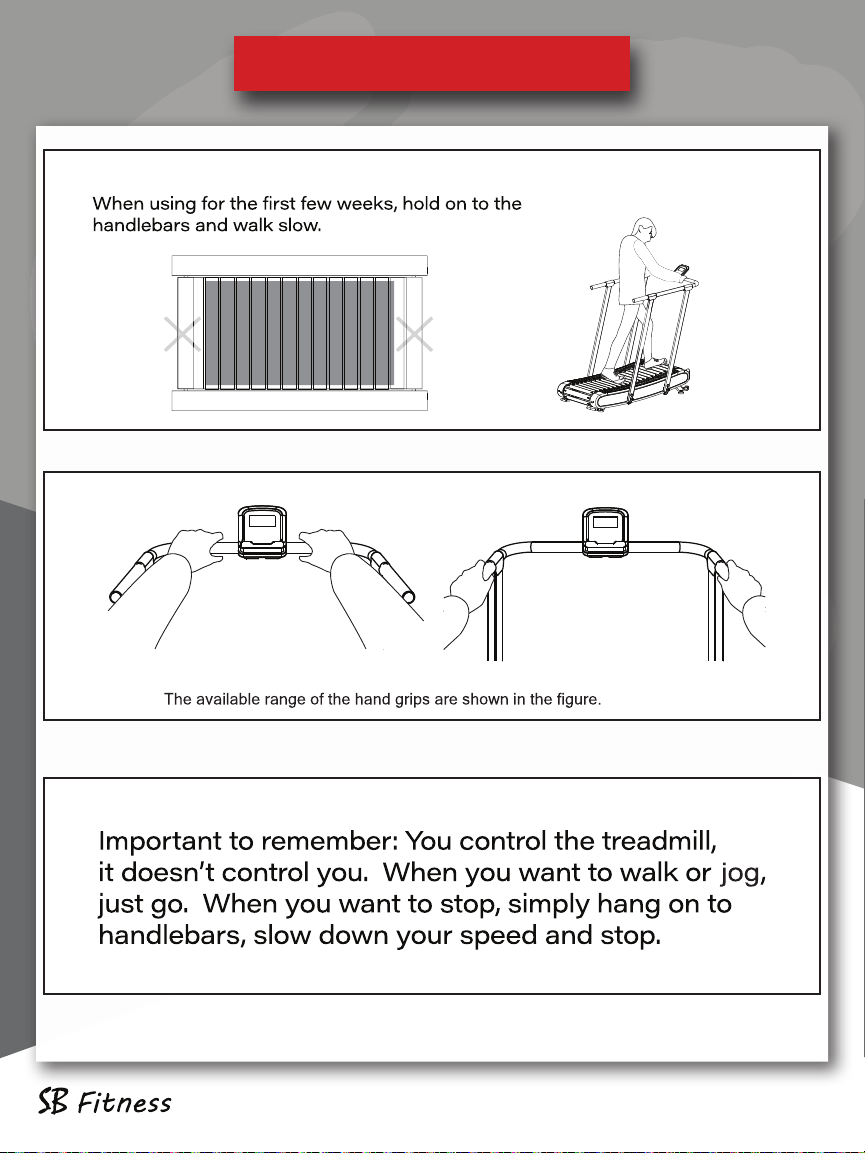
SB Filters CT 2500 User manual

This product has been manufactured with safety in mind. Warranty applies only when used as instructed. Failure to
comply with the warnings and precautions described in this document may cause personal injury and result in
warranty being voided. Please note that SB Fitness assumes no responsibility for any accidents resulting from use.

Table of Contents
Table of Contents
Hardware .............................................................................. 3
Product Overview ............................................................. 4
Assembly .......................................................................... 5-9
Directions for Use ..................................................... 10-12
Adjusting the Running Belt .................................. 13-15
Moving Your Treadmill ............................................ 16-17
How to Use Your Console ...................................... 18-20
Warranty ...................................................................... 21-22

Packing List
Hardware
CT250 pg 3
Packing List

Column
Product Overview
Product Overview CT250 pg 4

First, connect the data cable from the left column to the data cable ex-
tending from the treadmill, and then insert the data cable into the column
and the treadmill. Secondly, use the plug screw M10x16 to connect the
left and right columns to the tread-
mill, tighten, and then cover the
screw cover Ø25 on the column hole
where the plug screw is installed.
Finally, fasten the L-shaped knob on
the treadmill through the left and
right uprights, as shown in the figure.
Step 1:
Product Installation
Product Installation CT250 pg 5

Product Installation
Step 2:
Fasten the rear left and right uprights on the treadmill as
shown in the figure.
Connect the data cable from the front left column to the data
cable coming out of the handlebar.
CT250 pg 6
Product Installation

Step 3:
The handrail is fastened to the column with 8 flat round head
hexagonal screws M8x50,as shown in the figure.
Product Installation
CT250 pg 7
Product Installation

Step 4:
Install the 4 armrest covers using the 8 hexagon flat round head screws
M8x50, as shown in the figure.
Product Installation
CT250 pg 8
Product Installation

Step 5:
The console is connected to the treadmill with the two M5 x 15 screws. Be
sure to feed the data cable through the bottom opening of the console to
the rear part of the crossbar and connect to the data cable coming from
the cross bar/handlebar. Be careful to not let the data cable get pinched.
Place the monitor in the center of the stand and install it with screws.
Once you connect the data cable from the crossbar to the back of the
Console data cable, push all excess wire into the opening, provided in the
back of the console.
Product Installation
CT250 pg 9
Product Installation

Directions for Use
Directions for Use CT250 pg 10

Directions for Use
Directions for Use CT250 pg 11

Directions for Use
CT250 pg 12
Directions for Use

When using your CT250 treadmill, the pressure on the running belt may
not be balanced due to the different forces used by the two feet during
running, which causes the running belt to deviate from the center. This
deviation is not normal, and you need to bring the walking belt back to
the center.
Observe which side the walking belt is skewed while running.
If it is drifting to the left, use a hex wrench to turn the left screw clockwise
or the right screw 1/4 turn counterclockwise.
If it is drifting to the right, use a hex wrench to turn the right screw clock-
wise or the left screw 1/4 turn counterclockwise.
If the walking belt is not in the middle, repeat the above movements until
it is adjusted to the middle
Adjusting the Running Belt
CT250 pg 13
Adjusting the Running Belt

CT250 pg 14
Adjusting the Running Belt

To make adjustments to the running belt, you can access the adjustment bolts
through the holes in each end of the front and rear covers. These are the
access holes that you will insert the correct Allen wrench into to adjust the
bolts by turning either clockwise or counterclockwise as described in prior
instructions.
When the belt is biased to one side -
If you hear a sound other than the normal work-
ing sound, then your belt may be rubbing on
either side.
An adjusment bolt on the side of the belt is
included. Use the included hexagonal wrench,
turn clockwise little by little on the side the belt
is rubbing on. Avoid over tightening.
CT250 pg 15
Adjusting the Running Belt

Moving Your CT250 Treadmill
CT250 pg 16
Moving Your CT250 Treadmill
Transport handle in rear, transport wheels in the front. Bend your
knees,use your legs to pick CT250 up fromrear and moveto de-
siredlocation.

CT250 pg 17
Moving Your CT250 Treadmill

CT250 pg 18
Using Your Console
Using Your Console

CT250 pg 19
Using Your Console
Using Your Console
FUNCTIONAL BUTTON:
MODE:
- Press it to select functions.
- Hold it for 5 seconds to convert KM/H or Mile/H
SET:
- To set value of time, distance, calories and pulse , when not in scan mode.
RESET :
- Press to reset time, distance ,calories and pulse.
- Hold it for 3 seconds to reset time, distance , calories and pulse.
FUNCTION AND OPERATIONS:
1. SCAN:
- Press MODE button until “SCAN” appears, monitor will rotate through
the following functions: time, calories, speed, distance, total distance and
pulse. Each display will be hold 6 seconds.
2. TIME(TMR):
- Count the total time from exercise start to end.
3. SPEED(SPD):
- Display current steed.
4. DISTANCE(DST):
- Count the distance from exercise start to end.
5. CALORIES(CAL):
- Count the total calories from exercise start to end.
6. TOTAL DISTANCE(ODO):
- Count the total distance after installing the batteries.
7. PULSE RATE:
- Press MODE button until appears. Before measuring your pulse
rate, please place both your palms on the contact pads and the monitor
will show your current heart beat rate in beats per minute(BPM) on the
LCD after 3~4 seconds.

CT250 pg 20
Using Your Console
Remark: During the process of pulse measurement, because of the
contact jamming, the measurement value may be higher than the virtual
pulse rate during the first 2~3 seconds, then it will return to normal level.
The measurement value can not be regarded as the basis of medical treat-
ment.
8. AUTO ON/OFF & AUTO START/STOP:
- Without any signal for 4 minutes, the power will turn off automatically.
When the wheel is in motion or pressing the button, the monitor is in
action.
9. ALARM:
- The functions of time, distance and calorie can be set countdown, any
of above value goes to zero, the computer will alarm for 5 seconds.
After establishing a good target pulse, if the user’s actual pulse
exceed the target pulse, the electronic watch will have been reporting to
the police a hint.
Press MODE to select the function, then press SET to adjust the value.
Using Your Console
Table of contents
Other SB Filters Treadmill manuals