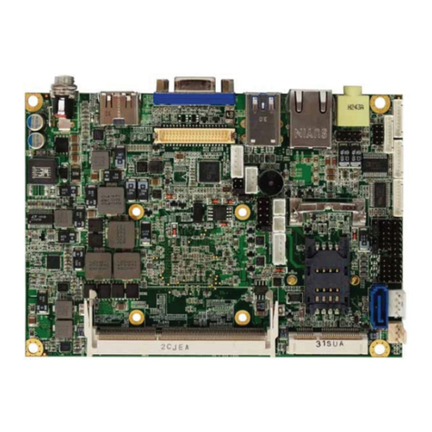
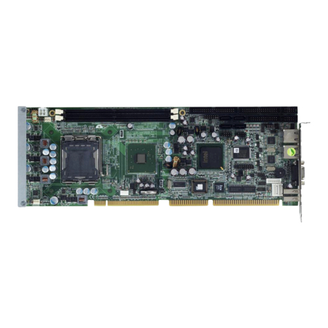
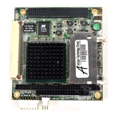
SBC PCM-5894 User manual

PCM-5894
PCM-5894C
All-in-One Single Board Pentium
Computer with SVGA, Ethernet
and 4 serial ports

FCC STATEMENT
THIS DEVICE COMPLIES WITH PART 15 FCC RULES.
OPERATIONISSUBJECT TOTHEFOLLOWING TWO
CONDITIONS:(1) THISDEVICE MAY NOT CAUSE HARM-
FULINTERFERENCE. (2)THIS DEVICEMUST ACCEPT
ANYINTERFERENCE RECEIVED INCLUDINGINTERFER-
ENCETHATMAYCAUSE UNDESIRED OPERATION.
THIS EQUIPMENT HAS BEEN TESTED AND FOUND
TO COMPLY WITH THE LIMITS FOR A CLASS "A"
DIGITAL DEVICE, PURSUANT TO PART 15 OF THE FCC
RULES. THESE LIMITS ARE DESIGNED TO PROVIDE
REASONABLE PROTECTION AGAINTST HARMFUL
INTERFERENCE WHEN THE EQUIPMENT IS OPERATED
IN A COMMERCIAL ENVIRONMENT. THIS EQUIP-
MENT GENERATES,USES, AND CAN RADIATE RADIO
FREQENCY ENERGYAND , IFNOT INSTATLLEDAND
USED IN ACCORDANCE WITH THE INSTRUCTION
MANUAL, MAY CAUSE HARMFUL INTERFERENCE TO
RADIO COMMUNICATIONS.OPERATION OF THIS
EQUIPMENT IN A RESIDENTIAL AREA IS LIKELY TO
CAUSE HARMFUL INTERFERENCE IN WHICH CASE
THE USER WILL BE REQUIRED TO CORRECT THE
INTERFERENCE AT HIS OWN EXPENSE.

Copyright Notice
This document is copyrighted, 1997. All rights are reserved. The
original manufacturer reserves the right to make improvements to
the products described in this manual at any time without notice.
No part of this manual may be reproduced, copied, translated or
transmitted in any form or by any means without the prior written
permission of the original manufacturer. Information provided in
this manual is intended to be accurate and reliable. However, the
original manufacturer assumes no responsibility for its use, nor
for any infringements upon the rights of third parties which may
result from its use.
Acknowledgements
AMD is a trademark of Advanced Micro Devices, Inc.
AMI is a trademark of American Megatrends, Inc.
Award is a trademark of Award Software International, Inc.
Cyrix is a trademark of Cyrix Corporation.
IBM, PC/AT, PS/2 and VGA are trademarks of International
Business Machines Corporation.
Intel and Pentium are trademarks of Intel Corporation.
Microsoft Windows ®is a registered trademark of Microsoft
Corp.
SMC is a trademark of Standard Microsystems Corporation.
RTL is a trademark of Realtek Semi-Conductor Co., Ltd.
C&T is a trademark of Chips and Technologies, Inc.
UMC is a trademark of United Microelectronics Corporation.
ITE is a trademark of Integrated Technology Express, INC.
SIS is a trademark of Slicon Integrated Systems Corp.
VIA is a trademark of VIA Technology, Inc.
All other product names or trademarks are properties of their
respective owners.
Part No. 2006589400 Manual PCM-5894 1st Edition
Printed in Taiwan November 1997

Packing list
Before you begin installing your card, please make sure that the
following materials have been shipped:
• 1 PCM-5894/PCM-5894C All-in-One Single Board Computer
• 1 User's Manual (This book)
• 1 utility disk with Ethernet drivers
• 4 utility disks with PCI SVGA utility programs and drivers for
Windows 3.1, Windows 95, Windows NT 3.51, Windows NT
4.0 and OS/2
The mainboard require several cables for normal operation. You
can make them yourself or purchase an optional cable kit PCM-
10489-1.
If you need revised version manual, Driver and Utility, you may
visit our Internet home page (www.emacinc.com) and download
it.
If any of these items are missing or damaged, contact your
distributor or sales representative immediately.

Contents
Chapter 1: General Information .......................... 1
Introduction .............................................................................. 2
Features .................................................................................... 3
Specifications ............................................................................ 4
Boarddimensions ..................................................................... 7
Chapter 2: Installation ......................................... 9
Jumpersand connectors ...................................................... 10
Locatingjumpers.................................................................. 12
Locating connectors ............................................................. 13
Setting jumpers ..................................................................... 14
CPUinstalling andupgrading ............................................. 15
System clock setting (J2) ........................................................ 16
CPU frequency ratio (J8)........................................................ 17
CPU type select (J10)............................................................. 17
CPU voltage setting (J12) ....................................................... 18
Installing DRAM(SIMMs) .................................................. 19
DiskOnChip socket (U16) .................................................... 20
Memory address selection (J13) .......................................... 21
IDEhard driveconnector (CN11) ....................................... 22
IDE hard drive connector (CN11)........................................... 23
Floppy drive connector (CN16) ........................................... 24
Floppy drive connector (CN16) .............................................. 25
Parallelport connector(CN13) ............................................ 26
Keyboard and mouse connector (CN9) .............................. 27
Front panel connector (CN6)............................................... 28
LCD Connector driveing voltage select (J3 and J11) ........ 29
Flat panel display connector (CN3) .................................... 29
Flat panel display connector (CN3)......................................... 30
Power connectors (CN8, CN12, CN2 and CN17)............... 31
Fan power connector (CN2 and CN17).................................. 31

Serialports (CN15)............................................................... 32
Serialport RS-232/422/485 selection...................................... 33
CMOS setup (J7) .................................................................. 34
COM3/COM4 RI pin setting (J20, J21).................................. 34
CMOS setup (J7) .................................................................. 34
VGA interface connections .................................................. 35
CRT display connector (CN1) ................................................ 35
Ethernetconfiguration ......................................................... 36
LAN LED connector (J14, J15, J16)................................... 36
Ethernet 100/10BASE connector (CN14)............................... 36
Network boot.......................................................................... 37
IrDAconnector (CN10)........................................................ 38
USB connector (CN5)........................................................... 38
Chapter 3: AMIBIOS Setup .................................. 39
Generalinformation............................................................. 40
StandardCMOS Setup ........................................................ 41
AdvancedCMOS Setup ....................................................... 43
AdvancedChipset Setup ...................................................... 48
PowerManagement Setup ................................................... 50
PCI/Plug and Play Setup ..................................................... 53
PeripheralSetup ................................................................... 58
Auto-detect hard disk........................................................... 61
ChangeSupervisorPassword .............................................. 61
Auto Configuration with Optimal Settings ........................ 62
Auto Configuration with Fail Safe Settings........................ 62
Save Settings and Exit .......................................................... 62
ExitWithout Saving ............................................................. 62
Chapter 4: Flat Pan el/CRT Controller Display
Drivers and Utilities ........................ 63
SoftwareDrives ..................................................................... 64
Hardwareconfiguration .......................................................... 64
Necessaryprerequisites........................................................... 65
Bofore you begin .................................................................... 65
Windows95 ........................................................................... 66

Driver installation .................................................................... 66
Windows 3.1 .......................................................................... 67
Driver installation .................................................................... 67
OS/2 ....................................................................................... 68
WindowsNT3.51................................................................... 70
WindowsNT 4.0.................................................................... 71
Chapter 5: SiS 5598 VGA Drivers ........................ 73
SystemRequirements ........................................................... 74
DOSUtility............................................................................ 74
NT3.5x ................................................................................... 77
NT 4.0 .................................................................................... 78
Selecting resolution and color depth .................................. 79
Windows95 ........................................................................... 80
Windows 3.x .......................................................................... 82
OS/2 Ver. 2.1.......................................................................... 84
OS.2 Warp 3.0 (Double Byte Character) ............................ 84
OS.2Warp 3.0(Single ByteCharacter) .............................. 86
Chapter 6: Ethernet Software configuration ... 87
Ethernetsoftwareconfiguration .......................................... 88
Appendix A: Programming the Watchdog Timer .
......................................................... 89
Programmingthe watchdog timer....................................... 90
Appendix B: Installing PC/104 Modules ............. 93
InstallingPC/104modules ...................................................... 94
Appendix C: Optional Extras .............................. 97
PCM-10489-1 Cable kit for PCM-5894 .............................. 98
PCM-10589-1PCIinterface risercard................................ 98


Chapter 1 General Information 1
1
General
Information
This chapter gives background informa-
tion on the mainboard.
Sections include:
• Card specifications
• Card layout and dimensions
CHAPTER

2PCM-5894 User'sManual
Introduction
The PCM-5894 is a Pentium single board computer with one on-
board PCI SVGA controller, one PCI Ethernet interface and one
PCI expansion slot. Equipped with 64 bits local bus architecture,
the PCM-5894 releases Pentium's full potential and provides
unprecedented performance compared to current 32-bit proces-
sor boards. The PCM-5894 offers all the functions of industrial
computer on a single board, but fits in the space of a 5¼" floppy
drive (only 5.75" x 8"). For maximum performance, the PCM-
5894 also supports 2nd level cache 512 KB on board. SSD
interface supports one 32-pin DIP socket for M-system DiskOn-
Chip 2000 series, memory capacity from 2 MB to 72MB.
On-board features include four serial ports (three RS-232 and
one RS-232/422/485), one multi-mode parallel (ECP/EPP/SPP)
port, one floppy drive controller and one keyboard/PS/2 mouse
interface. The built-in high speed PCI IDE controller supports
both PIO and bus master modes. Up to two IDE devices can be
connected, including large hard disks, CD-ROM drives, tape
backup drives and other IDE devices.
The PCM-5894 also features power management to minimize
power consumption. It complies with the “Green Function”
standard and supports three types of power saving features: Doze
mode, Standby mode and Suspend mode. In addition, the board’s
watchdog timer can automatically reset the system or generate an
interrupt in case the system stops due to a program bug or EMI.
On-board peripherals with true PCI
performance
The PCM-5894 is a highly integrated, all-in-one single board
computer. All on-board peripherals (including PCI flat panel/VGA
interface, PCI Ethernet and PCI IDE) adopt PCI technology and
operate through internal PCI bus. Integrating a Pentium board with
PCI architecture has unleashed a revolutionary level of perfor-
mance. The PCM-5894 is the smallest and most powerful all-in-
one Pentium board available.
This manual suits for next models
1
Table of contents
