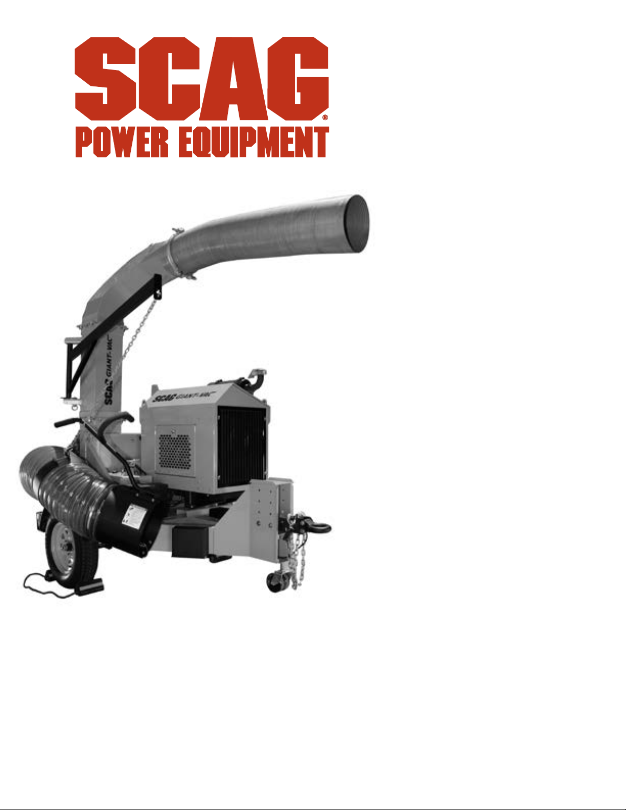
Scag Power Equipment TLB25-49KBD User manual

PART NO. 03559
PRINTED 9/2023
PRINTED IN USA
© 2023
Scag Power Equipment
Division of Metalcraft of Mayville, Inc.
Congratulations on owning a Scag Power Equipment Truck Loader! This manual
contains the operating instructions and safety information for your Scag Power
Equipment Truck Loader. Reading this manual can provide you with assistance
in maintenance and adjustment procedures to keep your Truck Loader
performing to maximum efciency. The specic models that this book covers
are listed on the inside cover. Before operating your Truck Loader, please read
all the information enclosed.
OPERATOR’S
MANUAL
TRUCK LOADER
Industrial Tow Behind
Model: TLB25-49KBD
*Actual product may differ from photo

WARNING
FAILURE TO FOLLOW SAFE OPERATING PRACTICES MAY RESULT
IN SERIOUS INJURY OR DEATH.
• Read this manual completely as well as other manuals that came with your Truck
Loader.
• ALWAYS FOLLOW OSHA APPROVED OPERATION.
• Become familiar with the safe operation of the equipment, operator controls and
safety signs.
• Check operation of brake, tail, marker and license plate lights frequently. Replace
as required.
• Make sure the operator of the tow vehicle has the operator of the Truck Loader in
full view at all times. Also, when operating the unit, instruct the operator to stay to
the side of the machine, never in front or behind.
• Keep all shields and guards securely in place.
• Be sure all safety features are attached, adjusted and functioning properly.
• Before performing any maintenance or service, stop the machine and remove the
spark plug wire.
• If a mechanism becomes clogged, stop the engine and wait for all moving parts to
stop before cleaning.
• Keep hands, feet and clothing away from power-driven parts.
REMEMBER - YOUR TRUCK LOADER IS ONLY AS SAFE AS THE OPERATOR!
HAZARD CONTROL AND ACCIDENT PREVENTION ARE DEPENDENT UPON THE AWARENESS,
CONCERN, PRUDENCE, AND PROPER TRAINING OF THE PERSONNEL INVOLVED IN THE
OPERATION, TRANSPORT, MAINTENANCE, AND STORAGE OF THE EQUIPMENT.
This manual covers the operating instructions and illustrated parts list for:
TLB25-49KBD with a serial number of X8900001 to X8999999
Always use the entire serial number listed on the serial number tag when referring to this product.

I
R
Table of Contents
Table of Contents
SECTION 1 - GENERAL INFORMATION...................................................................................1
1.1 INTRODUCTION.........................................................................................................................................1
1.2 DIRECTION REFERENCE.........................................................................................................................1
1.3 SERVICING THE ENGINE AND DRIVE TRAIN COMPONENTS...........................................................1
1.4 SYMBOLS ...................................................................................................................................................2
SECTION 2 - SAFETY INFORMATION ......................................................................................3
2.1 INTRODUCTION.........................................................................................................................................3
2.2 SIGNAL WORDS ........................................................................................................................................3
2.3 BEFORE OPERATION CONSIDERATIONS............................................................................................3
2.4 OPERATION CONSIDERATIONS.............................................................................................................5
2.5 MAINTENANCE CONSIDERATIONS AND STORAGE ..........................................................................6
2.6 USING A SPARK ARRESTOR...................................................................................................................6
2.7 SAFETY AND INSTRUCTIONAL DECALS..............................................................................................7
SECTION 3 - SPECIFICATIONS ................................................................................................8
3.1 ENGINE .......................................................................................................................................................8
3.2 IMPELLER...................................................................................................................................................8
3.3 WEIGHTS AND DIMENSIONS ..................................................................................................................8
SECTION 4 - OPERATING INSTRUCTIONS ...........................................................................10
4.1 CONTROLS AND INSTRUMENT IDENTIFICATION ............................................................................10
4.2 INITIAL RUN-IN PROCEDURES............................................................................................................. 11
4.3 CONNECTING TO TOW VEHICLE ......................................................................................................... 11
4.4 STARTING THE ENGINE.........................................................................................................................12
4.5 OPERATION..............................................................................................................................................12
4.6 HILLSIDE OPERATION ...........................................................................................................................13
4.7 UNCOUPLING THE UNIT FROM THE TOW VEHICLE ........................................................................13
4.8 AFTER OPERATION ................................................................................................................................14
4.9 REMOVING CLOGGED MATERIAL .......................................................................................................15
SECTION 5 - MAINTENANCE..................................................................................................16
5.1 MAINTENANCE CHART - RECOMMENDED SERVICE INTERVALS ................................................16
5.2 ENGINE OIL ..............................................................................................................................................17
5.3 ENGINE FUEL SYSTEM ..........................................................................................................................17
5.4 ENGINE AIR CLEANER...........................................................................................................................17
5.5 IMPELLER DRIVE BELT ADJUSTMENT...............................................................................................17
5.6 IMPELLER SHAFT BEARINGS AND ENGINE STUB SHAFT............................................................. 18
5.7 WHEELS AND TIRES...............................................................................................................................19
5.8 TRAILER LIGHTS.....................................................................................................................................19
SECTION 6 - ILLUSTRATED PARTS LIST..............................................................................20

II
R
Table of Contents
SCAG APPROVED ATTACHMENTS AND ACCESSORIES. ..................................................................... 20
INTAKE AND DISCHARGE ASSEMBLY......................................................................................................22
IMPELLER HOUSING AND TRAILER ASSEMBLY ....................................................................................24
IMPELLER DRIVE ASSEMBLY.....................................................................................................................26
KUBOTA ENGINE ASSEMBLY .....................................................................................................................28
FUEL AND ELECTRICAL SYSTEM..............................................................................................................30
TLB25 - TRUCK LOADER DECALS.............................................................................................................32
LIMITED WARRANTY .............................................................................INSIDE BACK COVER

1
Section 1 R
1.1 INTRODUCTION
Your Scag Power Equipment product was built to the
highest standards in the industry. However, the prolonged
life and maximum efficiency of your Truck Loader
depends on you following the operating, maintenance
and adjustment instructions in this manual.
If additional information or service is needed, contact your
Authorized Scag Power Equipment Dealer.
We encourage you to contact your Authorized Scag
Power Equipment Dealer for repairs. All Scag Power
Equipment dealers are informed of the latest methods to
service this equipment and provide prompt and efficient
service in the field or at their service shop. They carry a
full line of Scag Power Equipment service parts.
- IMPORTANT -
The replacement of any part on this product
by other than the manufacturer's authorized
replacement part may adversely affect the
performance, durability or safety of this product.
Use of other than original Scag Power Equipment
replacement parts will void the warranty.
When ordering parts, always give the model and serial
number of your product. The serial number plate is
located on the frame next to the engine.
USE ONLY SCAG POWER EQUIPMENT
APPROVED ATTACHMENTS AND ACCESSORIES.
Attachments and accessories manufactured by
companies other than Scag Power Equipment are not
approved for use on this machine. See Section 6-1.
GENERAL INFORMATION
WARNING
For pictorial clarity, some illustrations and gures
in this manual may show shields, guards or plates
open or removed. Under no circumstances should
this product be operated without these devices
in place.
All information is based upon product information
available at the time of approval for printing. Scag Power
Equipment reserves the right to make changes at any
time without notice and without incurring any obligation.
1.2 DIRECTION REFERENCE
The “Right” and “Left”, “Front” and “Rear” of the machine
are referenced from the operator’s right and left when
in the normal operating position and facing the forward
travel direction.
1.3 SERVICING THE ENGINE AND DRIVE
TRAIN COMPONENTS
Details regarding the service and repair of the engine
are not covered in this manual; only routine maintenance
and general service instructions are provided. For service
of these components during the limited warranty period,
it is important to contact your Authorized Scag Power
Equipment Dealer or find a local authorized servicing
agent of the component manufacturer. Any unauthorized
work done on these components during the warranty
period may void your warranty.

2
Section 1
R
1.4 SYMBOLS
SYMBOL DESCRIPTION SYMBOL DESCRIPTION
Choke
Transmission
On/Start
Spring Tension on Idler
Off/Stop
Oil
Spinning Fan Blades
Thrown Object Hazard
Fast
Slow
Continuously Variable - Linear Pinch Point
Keep Bystanders Away
Read Operator's Manual
481039S

3
R
Section 2
2.1 INTRODUCTION
Your Truck Loader is only as safe as the operator.
Carelessness or operator error may result in serious bodily
injury or death. Hazard control and accident prevention are
dependent upon the awareness, concern, prudence, and
proper training of the personnel involved in the operation,
transport, maintenance and storage of the equipment.
Make sure every operator is properly trained and thoroughly
familiar with all of the controls before operating. The owner/
user can prevent and is responsible for accidents or injuries
occurring to themselves, other people or property.
This product is capable of amputating hands and feet and
throwing objects. Always follow all safety instructions on this
product and in the manual to avoid personal injury or death.
READ THIS OPERATOR’S MANUAL AND WATCH
THE TIPS FOR SAFE OPERATION OF YOUR
SCAG ZERO-TURN MOWER VIDEO BEFORE
ATTEMPTING TO START YOUR MOWER. MAKE
SURE THAT EVERYONE KNOWS WHERE THE
MANUAL IS LOCATED AND KEEP A RECORD OF
EACH EMPLOYEE THAT HAS READ THE MANUAL.
A replacement manual is available from your Authorized
Scag Power Equipment Dealer or by contacting Scag
Power Equipment Service Department at P.O. Box 152,
Mayville, WI 53050 or contact us via the Internet at www.
scag.com. The manual for this machine can be downloaded
by using the model and serial number or use the contact
form to make your request. Please indicate the complete
model and serial number of your Scag Power Equipment
product when requesting replacement manuals.
2.2 SIGNAL WORDS
This symbol means “Attention! Become Alert! Your
Safety is Involved!" The symbol is used with the following
signal words to attract your attention to safety messages
found on the decals on the machine and throughout this
manual. The message that follows the symbol contains
important information about safety. To avoid injury and
possible death, carefully read the message! Be sure to
fully understand the causes of possible injury or death.
SIGNAL WORD:
It is a distinctive word found on the safety decals on the
machine and throughout this manual that alerts the viewer
to the existence and relative degree of the hazard.
DANGER
The signal word “DANGER” denotes that an extremely
hazardous situation exists on or near the machine that
could result in high probability of death or irreparable injury
if proper precautions are not taken.
WARNING
The signal word “WARNING” denotes that a hazard exists
on or near the machine that can result in injury or death if
proper precautions are not taken.
CAUTION
The signal word “CAUTION” is a reminder of safety
practices on or near the machine that could result in
personal injury if proper precautions are not taken.
Your safety and the safety of others depends significantly
upon your knowledge and understanding of all correct
operating practices and procedures of this machine.
2.3 BEFORE OPERATION
CONSIDERATIONS
1. Check the engine oil level and add oil as needed
to bring the level up to the FULL mark. See engine
owner's manual for oil specifications.
2. NEVER allow children to operate this machine. Do
not allow adults to operate this machine without
proper instructions.
3. Keep bystanders, children and pets away from the
machine.
SAFETY INFORMATION

4
RSection 2
4. Do not operate when children and/or others are
present. Keep children out of the work area and in
the watchful care of a responsible adult other than
the operator. Be alert and turn machine off if a child
enters the area.
5. DO NOT allow children to ride or play on the
machine, it is not a toy.
6. Keep keys stored in a safe location when the Truck
Loader is not in use; i.e. where they are inaccessible
to children.
7. DO NOT operate the machine under the influence of
alcohol or drugs.
8. Before and during reverse operation, look behind
and down for small children and/or pets.
9. If the operator(s) or mechanic(s) cannot read
English, it is the owner's responsibility to explain this
material to them.
10. DO NOT wear loose fitting clothing. Loose clothing,
jewelry or long hair could get tangled in moving
parts. Do not operate the machine wearing shorts;
always wear adequate protective clothing including
long pants. Wearing safety glasses, safety shoes
and a helmet is advisable and is required by some
local ordinances and insurance regulations.
WARNING
Always wear hearing protection. Operating this
machine over prolonged periods of time can
cause loss of hearing.
11. Keep the machine and attachments in good
operating condition. Keep all shields and safety
devices in place. If a shield, safety device or decal
is defective or damaged, repair or replace it before
operating the machine.
WARNING
Belts, belt guards, hoses, intake nozzles and
discharge tubes are subject to wear, damage and/
or deterioration, which could expose moving parts
or allow objects to be thrown. Frequently check
components and replace with manufacturer's
recommended parts when necessary.
12. Thoroughly inspect the area where the equipment is
to be used and remove all foreign objects.
13. Evaluate the terrain to determine what accessories
and attachments are needed to properly and safely
perform the job. Use only approved attachments and
accessories.
14. See Section 5.3 ENGINE FUEL SYSTEM for fueling
procedure.
15. Use a funnel or spout to prevent spillage.
16. DO NOT start the engine until any spilled fuel has
been cleaned up or has evaporated.
17. Never refuel indoors.
18. Keep flammable objects (cigarettes, matches, etc.),
open flames and sparks away from the fuel tank and
fuel container. Use only approved containers.
WARNING
Fuel is highly flammable. Take the following
precautions:
Store fuel in containers specically designed for
this purpose.
Refuel outdoors only and do not smoke while
refueling.
Add fuel before starting the engine. Never remove
the cap on the fuel tank or add fuel while the
engine is running or when the engine is hot.
If fuel is spilled, do not attempt to start the engine
but move the machine away from the area of
spillage and avoid creating any source of ignition
until fuel vapors have disappeared.
Replace all fuel tank and container caps securely.
19. Check the inlet hose, discharge tube, wear liners,
impellers, debris receiver box and components
frequently for signs of wear or deterioration and
replace as needed to prevent injury from thrown
objects going through weak or torn spots.
20. Never attempt to make any adjustments while the
engine is running unless specifically recommended
by the manufacturer.
21. Check the engine mounting bolts at frequent
intervals for proper tightness.
22. Use care when hooking or unhooking the machine to
a tow vehicle.

5
R
Section 2
23. Check operation of brake, tail, side marker and
license plate lights frequently. Replace failed or
damaged parts as needed.
2.4 OPERATION CONSIDERATIONS
This Truck Loader is designed for use at highway speeds
in normal conditions.
CAUTION
Tow at speeds appropriate for conditions. Reduce
speeds for:
• Rough Roads
• Winding Roads
• Cornering
• Adverse weather including rain, snow, ice and
high winds
1. Know the function of all controls and how to stop
quickly in case of an emergency.
2. Do not carry passengers. Keep bystanders, children
and pets away from the machine.
3. Make sure the hose and boom are secured before
transporting your Truck Loader.
4. Do not operate without the discharge connected to a
debris receiver box.
5. Do not overload the machine by attempting to chip
or shred any material beyond the manufacturer's
recommendation.
6. Do not operate on slopes if you are uneasy or
uncertain. Ultimate responsibility for safe operation
on slopes rests with the operator.
7. Exercise extreme caution when making turns or
changing direction on slopes. Keep all movements
slow and gradual.
8. Slow down and use caution when making turns and
crossing roads and side walks.
9. Be sure of your footing. Poor footing could cause a
slip and fall accident.
10. When using this machine, never direct the material
being collected toward bystanders or allow anyone
near the machine while in operation.
11. Do not operate around cars, windows, or other items
which could be damaged by blown debris.
12. Before attempting to start the engine, inspect the
machine, inlet hose, discharge, debris receiver box,
shields and safety devices for any damage. Correct
any problems before operating.
13. Stop on level ground and shut off the engine before
leaving the operator's position for any reason
including emptying the debris box or clearing an
obstruction in the intake or discharge.
14. If the Truck Loader ever plugs, shut off the engine,
and wait for all movement to stop before removing
the obstruction.
WARNING
DO NOT use your hand to dislodge the clogged
material. Use a stick or other device to remove
clogged material after the engine has stopped
running and the blower fan has stopped turning.
15. If the machine begins to vibrate abnormally, shut the
machine off immediately. Inspect the machine and
have repairs made before restarting.
16. Be alert for holes, rocks, roots and other hidden
hazards in the terrain. Cautiously enter a new area.
Be alert for hidden hazards.
17. Do not operate near drop-offs, ditches or
embankments. You could lose your footing, balance
or drive the machine off the edge.
18. Use only in daylight or good artificial light.
19. Do not leave the machine unattended.
20. The machine and attachments should be stopped
and inspected for damage after striking a foreign
object, and damage should be repaired before
restarting and operating the machine.
21. Keep hands and feet away from blower intake and
discharge. Contact can injure.
CAUTION
Do not touch the engine or the muer while the
engine is running or immediately after stopping.
These areas may be hot enough to cause a burn.

6
RSection 2
DANGER
DO NOT run the engine inside a building or
a confined area without proper ventilation.
Exhaust fumes are hazardous and contain carbon
monoxide which can cause brain injury and death.
22. Keep hands and feet away from all other moving
parts. Contact can injure.
23. Use care when approaching blind corners, shrubs,
trees, or other objects that may obscure vision.
24. NEVER leave the machine running unattended.
2.5 MAINTENANCE CONSIDERATIONS
AND STORAGE
1. Check wear liners and impeller on a regular basis
for bent, worn or cracked blades. Only replace
impellers. Do not straighten or weld the impeller
fan.
2. Never make adjustments to the machine with the
engine running unless specifically instructed to do
so. If the engine is running, keep hands, feet, and
clothing away from moving parts.
3. Never operate the machine when uncoupled from
the tow vehicle.
4. Remove the ignition key to prevent accidental
starting of the engine when servicing or adjusting
the machine. Wait for all movement to stop before
adjusting, cleaning or repairing.
5. Keep all nuts, bolts and screws tight, especially
the impeller bolt, to ensure the machine is in safe
working condition.
6. Do not change the engine governor settings or
overspeed the engine. See the engine operator's
manual for information on engine settings.
7. To reduce fire hazard, keep the muffler and engine
free of grass, leaves, excessive grease, oil and
dirt.
8. Park the machine on level ground.
9. Block the wheels to prevent the machine from
moving.
10. Lower the Support Leg to the ground and secure
with the spring latch when the machine is not
attached to a tow vehicle. See Figure 2-1.
SPRING LATCH
REAR SUPPORT
LEG
Lorem ipsum
Figure 2-1. Lowering the Rear Support Leg
11. NEVER allow untrained personnel to service the
machine.
12. Keep all parts in good working condition. Replace all
worn or damaged decals.
13. Use jack stands to support components when
required.
14. Let the engine cool before storing.
15. Keep the unit locked in a secure location and
disconnect the battery to prevent unauthorized
personnel, especially children, from playing and/or
tampering with the unit.
16. DO NOT store the machine near an open flame.
17. Always follow the engine manufacturer's
recommendation for storing and returning to service.
18. Shut off fuel while storing or transporting.
2.6 USING A SPARK ARRESTOR
The engine on this machine may not be equipped with a
spark arrestor muffler. It is in violation of California Public
Resource Code Section 4442 to use or operate this engine
on or near any forest covered, brush covered or grass
covered land unless the exhaust system is equipped with
a spark arrestor meeting any applicable local or state laws.
Other states or federal areas may have similar laws. Check
with your state or local authorities for regulations pertaining
to these requirements.

7
R
Section 2
2.7 SAFETY AND INSTRUCTIONAL DECALS
484983
485122
485126
485139
Avoid injury from burns
- Shut off engine
- Allow to cool several minutes
- Remove cap slowly
- Do not overfill
DIESEL FUEL ONLY
484292
484292

8
RSection 3
SPECIFICATIONS
3.1 ENGINE
General Type ....................................................................................................Heavy Duty Industrial/Commercial Diesel
Model:
Scag Model TLB25-49KBD .................................................................................................................. Kubota V1803
Displacement:
Kubota V1803.............................................................................................................................1.826 L (111.4 cu. in.)
Type:
Kubota V1803................................................................................................................4-Cycle, Liquid Cooled Diesel
Cylinders.......................................................................................................................................................................... 3
Governor......................................................................Isochronous Type with Variable Speed Control Set At 2700 RPM
Idle Speed:
Kubota......................................................................................................................................................... 1200 RPM
Fuel Pump:
Kubota....................................................................................................................Mechanical with In-Line Fuel Filter
Fuel...............................................................................Ultra Low Sulfur Diesel Fuel with a minimum cetane rating of 40
Oil Pump...........................................................................................................................Full Pressure w/Full-Flow Filter
Starter........................................................................................................................ Electric Starting with Solenoid Shift
3.2 IMPELLER
Impeller Diameter ................................................................................................................................Balanced 25" Steel
Number of Blades.................................................................................................................................. 4 - Blade, 1/2"
CFM (cubic feet / min.) - TLB25-49KBD.................................................................................................................... 7318
Wear Liner ..........................................................................................................................................................1/4" Steel
Intake Hose ........................................................................................................................................................... 7' x 16"
Discharge .............................................................................................................................................................. 6' x 12"
3.3 WEIGHTS AND DIMENSIONS
Hitch Height...................................................................................................................................................... Adjustable
Optional Hitch Ball Diameter ..................................................................................................................................2-5/16"
Hitch Class Required.............................................................................................................................Class III or Larger
Discharge Height..................................................................................................................................................121-1/4"
Weight ..................................................................................................................................................................... 2550#
Tire Size:
(2) Rear .................................................................................................................................................ST205/17 D15
Tire Pressure:
(2) Rear .....................................................................................................................................................50 PSI Max.

9
R
Section 4
CAUTION
Do not attempt to operate this machine unless
you have read this manual. Learn the location and
purpose of all controls and instruments before
you operate.
4.1 CONTROLS AND INSTRUMENT
IDENTIFICATION
Before operating the Truck Loader, familiarize yourself with
all Truck Loader and engine controls. Knowing the location,
function and operation of these controls is important for
safe and efficient operation.
OPERATING INSTRUCTIONS
1. Ignition Switch (Figure 4-1). The ignition switch
is used to start the engine and has three positions;
OFF, ON, and START.
2. Engine Throttle Control (Figure 4-1). Use to
control the engine speed. Push the throttle control
button up (rabbit) to increase engine speed and
push the throttle control button down (turtle) to
decrease engine speed.
3. Hourmeter (Figure 4-1). Indicates the number of
hours the engine has been operated.
4. Tongue Jack (Figure 4-1). Use to raise and lower
the ball hitch receiver or optional pintle hitch onto or
off of the tow vehicle.
REAR SUPPORT
LEG
TONGUE
JACK
INTAKE HOSE
BOOM ASSEMBLY
FUEL TANK
GAUGE
FUEL SHUTOFF
VALVESAFETY CHAINS
ENGINE THROTTLE
CONTROL
ENGINE INDICATOR
LIGHTS
IGNITION
SWITCH
TACHOMETER
HOURMETER
Figure 4-1. Controls and Instruments

10
RSection 4
5. Safety Chains (Figure 4-1). Use to connect to the
tow vehicles cradle draw bar in criss-cross fashion in
case of an accidental disconnect.
6. Rear Support Leg (Figure 4-1). Use to support
the Truck Loader when disconnected from the tow
vehicle.
WARNING
Failure to lower the Rear Support Leg when the
Truck Loader is not connected to a tow vehicle
can result in unit rollover, unit damage and
personal injury.
7. Fuel Tank Gauge (Figure 4-1). Indicates the
amount of fuel in the fuel tank.
8. Fuel Shutoff Valve (Figure 4-1). Located on the
fuel tank. Use to shut off fuel supply to the engine.
Rotate the valve counter clockwise to supply fuel.
Rotate the valve clockwise to shut off fuel supply.
9. Intake Hose Boom Assembly (Figure 4-1). Use to
support the intake hose. The support chain can be
raised or lowered until the intake nozzle floats 2-3
inches from the ground to help make operation easy
and comfortable.
10. Hourmeter (Figure 4-1). Indicates the number of
RPM's the engine has being operated at.
11. Engine Indicator Lights (Figure 4-1). Indicates the
operation of the engine sensors for battery voltage,
oil pressure, water temperature and glow plug
pre-heat. If a problem occurs with a sensor on the
engine, the light will iluminate (excluding the glow
plug pre-heat). See your authorized Scag Power
Equipment Dealer for diagnosis and repair.
4.2 INITIAL RUN-IN PROCEDURES
FIRST DAY OF USE OR APPROXIMATELY 20 HOURS
1. Change the engine oil and oil filter after the first 20
hours of operation. (See Section 5.2).
2. Check for loose hardware. Tighten as needed.
3. Check tire pressure. Adjust pressure if necessary.
(See Section 5.3).
4.3 CONNECTING TO TOW VEHICLE
1. Back the tow vehicle up to the Truck Loader.
2. Raise or lower the tongue jack until the pintle ring on
the Truck Loader is higher than the horn of the pintle
hook on the tow vehicle.
3. With assistance behind, back up slowly, align the
pintle ring and pintle hook.
4. Lower the front of the Truck Loader using the wheel
jack until the pintle ring drops completely onto the
pintle hook and securely lock.
5. Connect the safety chains to the tow vehicle in
criss-cross fashion to the cradle draw bar in case of
accidental disconnect. See Figure 4-2.
Bottom View
Figure 4-2. Safety Chains
6. Connect the trailer wiring plug to the trailer socket on
the tow vehicle and check for proper operation of all
lights and signal indicators.
-NOTE-
The Truck Loader is equipped with a 7-Way flat
spade connector. If the tow vehicle is equipped with
anything other than a 7-Way flat spade connector,
an adapter will be required.
7. Pull and turn the spring latch to unlock the pin
securing the rear support leg in the lowered position.
See Figure 4-3.
SPRING LATCH
REAR SUPPORT
LEG
Figure 4-3. Raising the Rear Support Leg
8. Raise the rear support leg and secure in the
transport position using the spring latch.

11
R
Section 4
4.4 STARTING THE ENGINE
CAUTION
DO NOT USE STARTING FLUIDS. Use of starting
uids in the air intake system may be potentially
explosive or cause a “runaway” engine condition
that could result in engine damage and/or
personal injury.
1. Move the machine to a flat open area.
2. Be sure the fuel shutoff valve, located on the fuel
tank, is completely open. See Figure 4-1.
3. Move the engine throttle control to approximetly one-
fourth engine speed.
4. Turn the ignition key to the on position until the
indicator for the glow plugs goes out. Then turn the
ignition key to the START position and release the
key as soon as the engine starts. Do not hold the
key in the START position for more than 15 seconds
at a time. Allow at least 60 seconds between each
cranking attempt to prevent overheating of the
starter motor. Prolonged cranking can damage the
starter motor and shorten battery life.
5. Allow engine to warm before operating the Truck
Loader.
4.5 OPERATION
This Truck Loader has been designed to pick up dry
organic debris such as leaves, grass clippings, shavings
and small amounts of sand. Vacuuming hard non-
organic material will aect the life of your machine. Sand
is abrasive and will produce wear of items including the
blower housing, wear liners, impeller and nose cone.
WARNING
DO NOT operate the machine without being
attached to a tow vehicle and debris box. Always
wear eye, ear and breathing protection when
operating machine.
1. Read Section 2.3 BEFORE OPERATION
CONSIDERATIONS and Section 2.4 OPERATION
CONSIDERATIONS before operating.
CAUTION
Tow at speeds appropriate for conditions. Reduce
speeds for:
• Rough Roads
• Winding Roads
• Cornering
• Adverse weather including rain, snow, ice and
high winds
2. Adjust the height of the intake nozzle. For maximum
debris pickup, the intake nozzle should be as close
to the debris as possible without blocking airflow and
the engine speed should be set at full throttle.
3. Not all debris pick up will require that the engine
speed be set to "Fast". You can experiment with the
intake nozzle height and engine speed to best suit
your conditions.
4. Operating in dry dusty conditions may require
that the engine speed be set to a slower position
to reduce the amount of small particles of debris
escaping.
5. For peak performance, keep the debris box clean
and do not overfill.
6. Make sure the driver of the tow vehicle has the
operator in full view at all times.
7. When operating, instruct the operator to stay to the
side of the machine, never in front or behind.
WARNING
DO NOT remove the Truck Loader from the tow
vehicle or debris box with the engine running.
STOP the engine and allow all rotation to stop.
8. If the intake nozzle or discharge becomes plugged,
shut off the engine and remove the ignition key.
The engine must come to a complete stop before
attempting to remove obstruction from inlet nozzle
or discharge area. Using a stick or similar item,
dislodge the clogged material. Then resume normal
operation.

12
RSection 4
9. Plan how to clear the area to reduce clearing time.
10. Collecting debris into piles for the machine to
intercept prior to start up will save time and fuel as
well as wear and tear on the unit.
11. Keep the Truck Loader's intake nozzle and
discharge clean.
12. Use a slow travel speed when clearing heavy or
large amounts of material.
4.6 HILLSIDE OPERATION
Slopes are a major factor related to loss-of-control and tip
over accidents which can result in severe injury or death.
All slopes require extra caution.
WARNING
DO NOT operate on steep slopes. Poor footing
could cause a slip and fall accident. ALWAYS
FOLLOW OSHA APPROVED OPERATION.
1. Do not operate on slopes if you are uneasy or
uncertain. Ultimate responsibility for safe operation
on slopes rests with the operator.
2. Be sure of footing on slopes.
3. Caution must be used when operating on slopes,
especially when the grass is wet. Wet grass reduces
traction and control.
4. To prevent tipping or loss of control, keep all
movements on slopes slow and gradual.
5. Do not turn on slopes unless necessary, and then
turn slowly and down hill when possible.
6. Do not start or stop on slopes. If tires lose traction,
stop the unit and proceed slowly straight down the
slope.
7. Be alert for holes, rocks, roots, ruts and other hidden
hazards in the terrain. Uneven terrain could cause a
slip and fall accident.
8. Do not operate near drop-offs, ditches, or
embankments. The operator could lose footing or
balance or unit could suddenly turn over if a wheel is
over the edge of a cliff or ditch, or if the edge caves
in.
4.7 UNCOUPLING THE UNIT FROM THE
TOW VEHICLE
1. Park the machine on a flat, level surface only. Do not
park the machine on an incline.
2. Block the wheels to prevent the machine from
moving. See Figure 4-4.
Figure 4-4. Wheel Chocks
3. Disconnect the trailer wiring plug from the tow
vehicle.
4. Unhook the safety chains from the rear of the tow
vehicle.
5. Unlock the pintle hitch.
6. Crank down the tongue jack until the pintle ring on
the unit clears the pintle hook on the tow vehicle.

13
R
Section 4
7. Pull and turn the spring latch to unlock the pin
securing the rear support leg in the transport
position. See Figure 4-5.
SPRING LATCH
REAR SUPPORT
LEG
Figure 4-5. Lowering the Rear Support Leg
8. Lower the rear support leg to the lowermost position
and secure with the spring latch.
WARNING
Faiure to lower the Rear Support Leg when the
Truck Loader is not connected to a tow vehicle
can result in unit rollover, unit damage and
personal injury.
9. Pull the tow vehicle away.
4.8 AFTER OPERATION
1. When machine is not in operation, in storage or
transporting, lock the hose support boom and secure
hose on the storage pin. Pull and turn the spring
latch to lock the pin securing the hose support boom
in the transport position. See Figure 4-6 & Figure 4-7.
SPRING LATCH
HOSE SUPPORT
BOOM
Figure 4-6. Locking the Hose Support Boom
HOSE STORAGE
PIN
Figure 4-7. Hose Storage Pin
2. After the engine has cooled down, wash the entire
machine after each use. Do not use high pressure
spray or direct the spray onto electrical components.
- IMPORTANT -
Do not wash a hot or running engine. Cold water
will damage the engine. Use compressed air to
clean the engine if it is hot.

14
RSection 4
3. Keep the entire machine clean to inhibit serious heat
damage to the engine.
DANGER
To avoid injury from burns, allow the engine
to cool before removing the fuel tank cap and
refueling.
4. Check the tire pressure. Adjust pressure if
necessary. See Section 5.7.
4.9 REMOVING CLOGGED MATERIAL
DANGER
ROTATING FAN BLADES
NEVER PUT YOUR HANDS INTO THE VACUUM
INTAKE OR DISCHARGE FOR ANY REASON!
Shut o the engine, remove the ignition key and
only then use a stick or similar object to remove
material if plugging has occurred.
1. If the intake nozzle or discharge becomes plugged,
shut off the engine and remove the spark plug wire.
The engine must come to a complete stop before
attempting to remove obstruction from intake nozzle
or discharge area. Using a stick or similar item,
dislodge the clogged material. Then resume normal
operation.

15
Section 5 R
5.1 MAINTENANCE CHART - RECOMMENDED SERVICE INTERVALS
HOURS
PROCEDURE COMMENTS
BREAK-IN
(FIRST 10) 8 20 50 100 200 500
X Check all hardware for tightness
X Check impeller drive belt tension See Section 5.5
X Check engine oil level See engine operator's manual
X*Clean Truck Loader
XCheck trailer lights for proper
operation Check Daily before operating
XCheck condition of impeller blades
and impeller housing
X Check impeller drive belt tension See Section 5.5
X Change engine oil and filter See engine operator's manual
X *Clean air filter element See engine operator's manual
X **Grease Impeller Shaft Bearings See below for grease type
X**Grease Engine Output Shaft
Spline and Bearing See below for grease type
X Check condition of fuel lines
X Check all hardware for tightness
X Change engine oil See engine operator's manual
X *Clean air cleaner element See engine operator's manual
X *Clean Fuel Cup
X *Replace engine air filter See engine operator's manual
X Replace Spark Plug See engine operator's manual
* Perform these maintenance procedures more frequently under extreme dusty or dirty conditions.
** Use Scag Premium Spindle Grease NLGI #2 Grade (P/n 486258).
MAINTENANCE

16
Section 5
R
5. Never fuel the machine indoors or in an enclosed
trailer.
6. Never store the machine or fuel container where
there is an open flame, spark or pilot light such as on
a water heater or other appliances.
7. Never fill containers inside a vehicle or on a truck
or trailer bed with a plastic liner. Always place
containers on the ground away from your vehicle
before filling.
8. Keep the nozzle in contact with the rim of fuel tank
or container opening at all times until fueling is
complete. Do not use a nozzle lock-open device.
9. If fuel is spilled on clothing, change clothing
immediately and wash affected skin.
10. Replace gas cap and tighten securely.
5.4 ENGINE AIR CLEANER
A. CLEANING AND/OR REPLACING AIR
CLEANER ELEMENT
For any air cleaner, the operating environment dictates
the air cleaner service periods. Inspect and clean the
air cleaner element after every 50 hours of operation or
monthly, whichever occurs first and replace the element if
required or every 200 hours. Refer to the Engine Operator’s
Manual furnished with this Truck Loader for instructions.
- NOTE -
In extremely dusty conditions it may be necessary
to check the element once or twice daily to prevent
engine damage.
5.5 IMPELLER DRIVE BELT ADJUSTMENT
WARNING
Before removing any guards, shut the engine o
and remove the ignition key. Wait for all moving
parts to come to a complete stop before beginning
work.
1. Remove the belt cover.
2. Check the belt tension by using a belt tension
gauge. The belt should move 1/2" with 14 pounds of
pressure applied. See Figure 5-1.
5.2 ENGINE OIL
A. CHECKING ENGINE CRANKCASE OIL
LEVEL
The engine oil level should be checked after every 8 hours
of operation or daily as instructed in the Engine Operator’s
Manual furnished with this Truck Loader.
B. CHANGING ENGINE CRANKCASE OIL
After the first 20 hours of operation, change the engine
crankcase oil and replace the oil filter. Thereafter, change
the engine crankcase oil after every 100 hours of operation
or bi-weekly, whichever occurs first. Refer to the Engine
Operator’s Manual furnished with this Truck Loader for
instructions.
5.3 ENGINE FUEL SYSTEM
DANGER
To avoid injury from burns, allow the engine
to cool before removing the fuel tank cap and
refueling.
A. FILLING THE FUEL TANK
Fill the fuel tank at the beginning of each operating day.
Fill to aprroximately 1" below the top of the fuel tank
(approximately 8-1/2 gallons indicating Full (F) on the fuel
gauge) at the beginning of each operating day. Do not
overfill. Use clean, fresh ultra low sulfur diesel fuel with a
minimum cetane rating of 40.
To avoid personal injury or property damage, use extreme
care in handling diesel fuel.
1. Extinguish all cigarettes, cigars, pipes and other
sources of ignition.
2. Use only an approved fuel container.
3. Never remove the fuel cap or add fuel with the
engine running. Allow the engine to completely cool
before fueling.
4. DO NOT start the engine until any spilled fuel has
been cleaned up or has evaporated.
Table of contents
Other Scag Power Equipment Compact Loader manuals