ScaleART OHG Schillerstraße 3 67165 Waldsee
16.02.2012
Benötigtes Werkzeug:
- Kreuzschlitzschraubendreher
- Steckschlüssel 2.5mm
- Steckschlüssel 3mm
- Spitzzange
- Seitenschneider
- kleiner Hammer
- Skalpell
- Pinzette
- kleine Flachfeile
Haftungsausschluß / Schadenersatz:
Die Einhaltung der Montageanleitung sowie Bedienung, Installation, Betrieb und Wartung dieses Modells und aller
damit verwendeten Komponenten können von der Fa. ScaleART nicht überwacht werden. Daher übernimmt die
Fa. ScaleART keinerlei Haftung für Verluste, Schäden oder Kosten, die sich aus der fehlerhaften Verwendung und
Betrieb ergeben oder in irgendeiner Weise damit zusammenhängen.
Soweit gesetzlich zulässig, ist die Verpflichtung der Fa. ScaleART zur Leistung von Schadenersatz, gleich aus
welchem Rechtsgrund, begrenzt auf den Rechnungswert der an dem Schaden stiftenden Ereignis unmittelbar
beteiligten Produkte der Fa. ScaleART. Dies gilt nicht, soweit die Fa. ScaleART nach zwingenden gesetzlichen
Vorschriften wegen Vorsatz oder grober Fahrlässigkeit unbeschränkt haftet.
Ersatzteile:
Ersatzteile können unter Angabe der Artikelnummer des
Baukastens und der Stücklistennummer bei uns bestellt
werden.
Dieses Modell entstand mit der freundlichen Unterstützung und Genehmigung der MAN Nutzfahrzeug AG in München
Dieses Modell ist kein Spielzeug und für Jugendliche unter 14 Jahren nicht geeignet. Jegliche technische Änderung und
Modifikation behalten wir uns vor. Für Irrtümer und Druckfehler übernehmen wir keine Haftung. Nachdruck und
Vervielfältigung nur mit unserer ausdrücklichen, schriftlichen Genehmigung gestattet.
Benötigtes Material:
- Zweikomponentenkleber glasklar
- Sekundenkleber dickflüssig
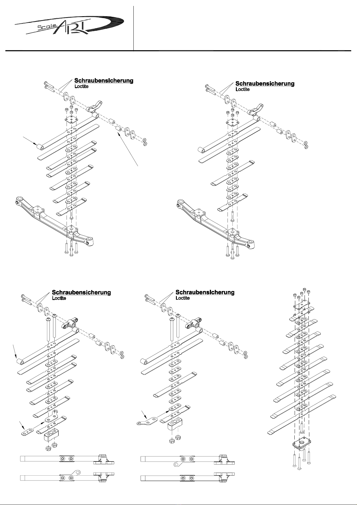
- Schraubensicherungsmittel
- Kreppklebeband
Allgemeine Anmerkungen zur Monage:
Lesen Sie die Bauanleitung vor der Montage durch und
verschaffen Sie sich einen Überblick über die benötigten
Bauteile und Werkzeuge
Die Modellbauschrauben M1,6 und M2 nicht zu fest
anziehen, da diese sonst abbrechen können.
Ebenso alle Schrauben in Kunststoffteilen nicht
überdrehen!
Klare Glasteile (Scheiben) werden mit Zweikomponen-
tenkleber eingeklebt.
Niemals Sekundenkleber mit Glasteilen in Verbindung
bringen. Glasteile können beim Verkleben mit
Kreppband fixiert werden.
Bei Bauteilen, die mit Sekundenkleber zu verkleben
sind, den Kleber nie direkt aus der Tube auftragen.
Besser ist es, den Sekundenkleber auf ein Stück Blech
oder Kunststoff aufzutragen und mit Hilfe einer
Stecknadel oder eines Papierstreifens auf das Bauteil
zu übertragen.
Inhalt des Montagekastens:
- Fahrerhaus MAN TGS M im Maßstab 1:14,5
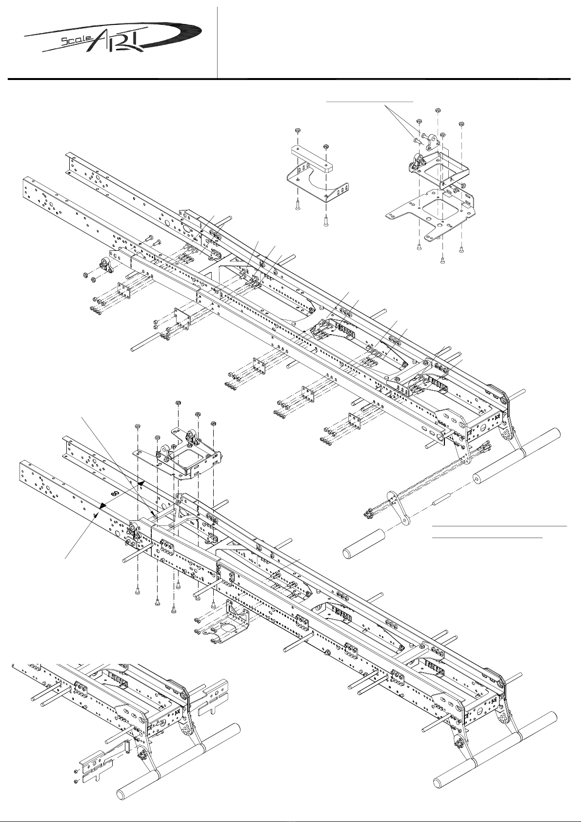
- Edelstahlrahmen
- Vorderachsaufhängung mit Blattfeder
- Hinterachsaufhängung mit Pendelaufhängung
- Metallvorderachsen
- Kippaufbau
- Aluminiumfelgen und Reifen
1:14,5
ca. 660mm
ca. 172mm
ca. 230mm
60mm
Sonderzubehör:
Ausbauteile für ferngesteuertes Funktionsmodell
Die Bestellnummern für das Sonderzubehör entnehmen
Sie der Stückliste
Technische Daten:
Maßstab:
Länge:
Breite:
Höhe:
Rahmenbreite:
four axle halfpipe tipper
4-Achs Halfpipe Kipper
MAN TGS