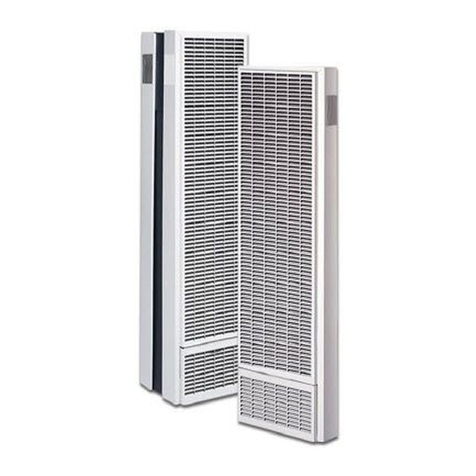
Ultra Gas Sauna Heaters
Installation Instructions
Note: Your Scandia/Vico gas sauna heater should be installed only by a licensed electrician and HVAC profes-
sional. Improper and unofficial installation will void warranty.
Roughing In
1. Set galvanized back-up wall in place on face of studs.
Centerline of the flue hole must be a minimum of 17 1/ 2
from side wall for 40,000 BTU models and 26 1/2 for
80,000 BTU models. The metal tabs at the bottom are
“spacers” and must rest on the finished floor. Nail to
studs.
2. The sides and top of galvanized back-up wall are used
as plaster grounds. If materials other than cement plaster
are used, fit material to edge of galvanized panel. If
wall is to be more than 3/4” thick, spacers must be used
between stud and back-up wall.
3. Adjust vent and air intake collars on back-up wall to wall
thickness. Each has plaster ground.
4. The rough-in portion of control box should be nailed on
stud facing outside the room and as far from the heater
as possible.
5. Place a nail 6” down from the ceiling on stud facing in-
side the sauna room. String a pull wire from the nail to
the control box. Use this wire to bull thermo-bulb through
the wall when the sauna room is finished. Do not bend
the capillary tubing more than 90 deg at any point.
6. Run the supplied low voltage wire from the control box
to the heater burner assembly brining it through the air
intake vent. An access hole has been provided on the
vent. This is a three wire assembly, two are used one is a
spare.
7. Run the gas line with shut off valve into the air intake
vent through the hole provided. Connect the gas line into
the base of the gas valve.
Finish
1. Place 1” fiberglass insulation into galvanized
back-up wall.
2. Remove paper from stainless flashing and start
screws to galvanized (do not tighten)
3. Slide heater into place, guide metal covered
high-limit wires through the hole on the intake
bracket. Secure heater to stainless steel flashing
with two screws.
4. Tighten screws on the corners of the flashing.
5. Slip burner inside heater allowing the burner lip
to fit under the burner bracket. Then bolt near
end of burner to the intake channel.
6. Place caution sign on flashing above heater.
7. Hook up low voltage wires on gas valve (see at-
tached illustration .
8. Install flue cap (outside wall) : or draft hood
(inside wall).
9. Pull thermo-bulb through wall and attach six
inches below ceiling as far away from heater as
possible.
10. Install heater guard rail.
40,000 BTU 80,000 BTU
A 18.5" 29"
B8" 12"
C7" 11"
D 2 1/2" 4"
0.515625" x 0.515625"
0.41129032258065" x 0.41129032258065"
0.20564516129032" x 0.20564516129032"
Cedar wall
lining
Gas Line
B
D
C
A
