SCE SCE-HE18W120V User manual

B
1
SAGINAW CONTROL & ENGINEERING • A/C USER MANUAL
1. User Manual ............................................................................................ p. 2
2. Legal Regulations................................................................................... p. 2
3. Safety Instructions ................................................................................. p. 3
4. Technical Information............................................................................. p. 4
5. Functional Principle ............................................................................... p. 4
6. Technical Data......................................................................................... p. 5
7. Performance Graph ................................................................................ p. 6
8. Mounting.................................................................................................. p. 7
9. Mounting Principle ................................................................................. p. 7
10. Cutout Dimensions................................................................................. p. 8
11. Dimensions (H x W x D) ......................................................................... p. 8
12. Electrical Connection ............................................................................. p. 9
13. Controller Programming ........................................................................ p. 9
14. Wiring Diagram ....................................................................................... p. 12
15. Taking Into Operation ............................................................................. p. 14
16. Repair....................................................................................................... p. 14
17. Maintenance & Cleaning ........................................................................ p. 15
18. Transportation & Storage....................................................................... p. 16
19. Parts Supplied......................................................................................... p. 16
20. Warranty / Limits of Liability ................................................................. p. 17
User Manual SCE-HE18W120V

B
2
SAGINAW CONTROL & ENGINEERING • A/C USER MANUAL
back to top
1. User Manual
This instruction manual contains information and instructions to enable the user to work safely, correctly and economically
on the unit. Understanding and adhering to the manual can help one:
• Avoid any dangers
• Reduce repair costs and stoppages
• Extend and improve the reliability and working life of the unit
PLEASE ENSURE TO USE THE RIGHT VERSION OF THE INSTRUCTION MANUAL SUITABLE FOR YOUR UNIT
Conditions of Use
The unit is to be used exclusively for the dissipation of heat from control cabinets and enclosures in order to protect
temperature sensitive components in an industrial environment. To meet the conditions of use, all the information and
instructions in the instruction manual must be adhered to.
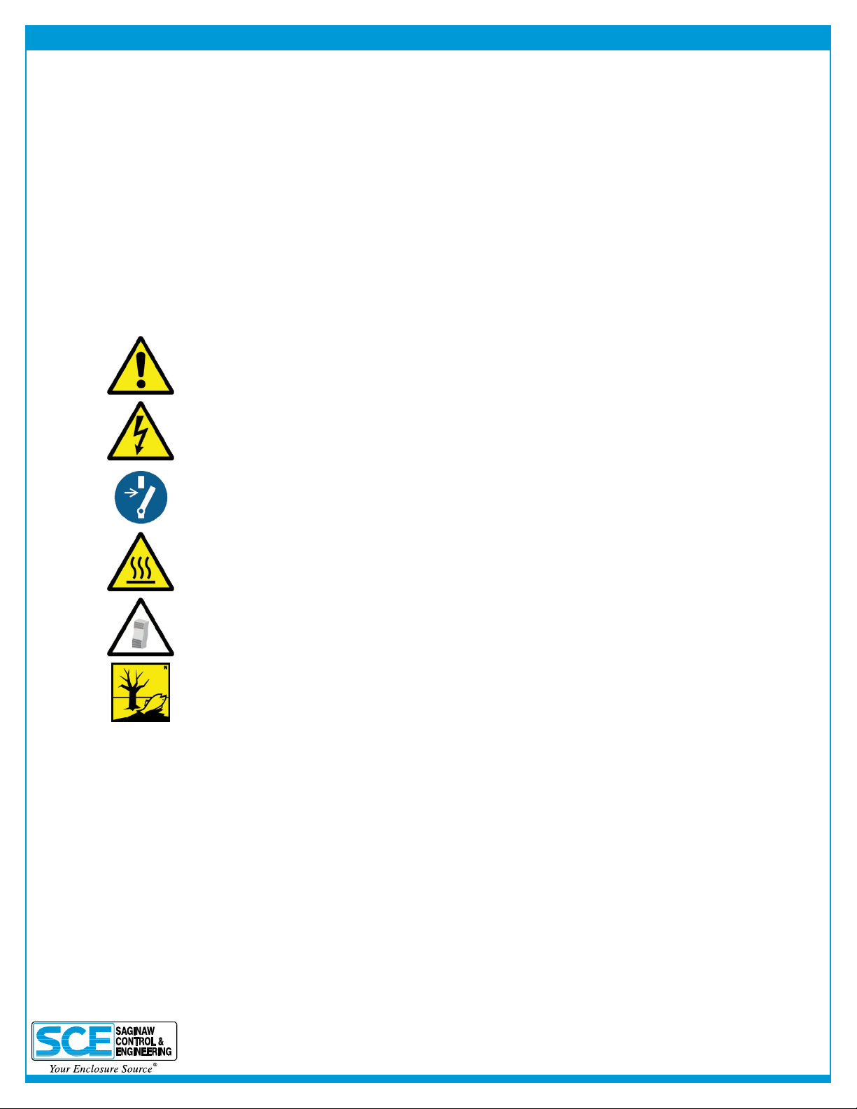
General Danger
Indicates compulsory safety regulations which are not covered by a specic pictogram such
as one of the following.
High Electric Voltage
Indicates electric shock danger.
Important Safety Instruction
Indicates instructions for safe maintenance and operation of the unit.
Attention
Indicates possible burns from hot components.
Attention
Indicates possible damage to the unit.
Instruction
Indicates possible danger to the environment.
2. Legal Regulations
Liability
The information, data and instructions contained in this instruction manual are current at the time of going to press. We
reserve the right to make technical changes to the unit in the course of its development. Therefore, no claims can be
accepted for previously delivered units based on the information, diagrams or descriptions contained in this manual. No
liability can be accepted for damage and production caused by:
• Disregarding the instruction manual
• Operation error
• Inappropriate work on or with the unit
• The use of non-specied spare parts and accessories
• Unauthorized modications or changes to the unit by the user or his personnel
Saginaw Control & Engineering is only liable for errors and omissions as outlined in the guarantee conditions contained in
the main contractual agreement. Claims for damages on any grounds are excluded.

B
3
SAGINAW CONTROL & ENGINEERING • A/C USER MANUAL
back to top
3. Safety Instructions
Upon delivery the unit is already meeting current technical standards, therefore it can be safely taken into operation. Only
trained specialists are allowed to work on the unit. Unauthorized personnel must be prohibited from working on the unit.
Operating personnel must inform their superiors immediately if any malfunction of the unit becomes apparent.
Please note that before starting to work on or with the unit, a procedure must be carried out inside the cabinet on which the
unit is to be mounted.
Before commencing work inside the cabinet, the control cabinet manufacturer’s instruction must be read with regards to:
• Safety instructions
• Instructions on taking the cabinet out of operation
• Instructions on the prevention of unauthorized cabinet reconnection
The electric equipment meets the valid safety regulations. One can nd dangerous voltage (above 50V AC or above 100V
DC):
• Behind the control cabinet doors
• On the power supply in the unit housing
The units have to be fused according to the type plate and the wiring diagram. Switch the unit off immediately if the electric
power supply is interrupted.
Danger Through Incorrect Work on the Unit
Only specialized personnel are allowed to maintain and clean the unit. Regular maintenance
and cleaning must be kept in order to ensure that the unit remains in perfect working condition
and has a long working life.
Danger from Electric Voltage
Only specialized personnel are allowed to maintain and clean the unit. The personnel must
ensure that for the duration of the maintenance and cleaning, the unit is disconnected from
the electrical supply.
Attention
Damage to the unit through the use of inappropriate cleaning materials. Please do not use
aggressive cleaning material.
Instruction
Damage to the environment through unauthorized disposal. All spare parts and associated
material must be disposed of according to the environmental laws.

B
4
SAGINAW CONTROL & ENGINEERING • A/C USER MANUAL
back to top
4. Technical Information
Concise Unit Description
Heat Exchangers are used where the heat generated by energy losses in control cabinets must be conducted away to
protect temperature-sensitive components. The characteristics graph shown in the “Performance Characteristics” section
applies to external (ambient) air as the coolant
In Air-to-Air Heat Exchangers, the internal temperature of the control cabinet cannot be cooler than the ambient temperature.
There are natural limits to the cooling performance, dependent on the air supply temperature and the requirement for a
temperature difference of at least 9° F. Unlike systems in which the heat generated is allowed to escape by air convection
through ventilation slots, with the Heat Exchanger, the clean air inside the control cabinet is prevented from mixing with the
air outside, which may well be unclean.
5. Functional Principle
Functional Principle
The Heat Exchanger is a cooling device that creates a heat-transfer through a large area of thin aluminum sheet metal
folded up in the Heat Exchanger core by means of forced convection. Used within an enclosure, it uses the ambient air as
the cooling medium, thus avoiding the utilization of refrigerant.
The cooling performance of the Heat Exchanger is dependant on the ambient (external) air temperature. The internal fan
is set to be always on. The external fan is controlled via a controller. When the cabinet temperature increases beyond the
pre-set thermostat temperature, the external fan is switched on and the Heat Exchanger starts cooling. Cooling stops when
the cabinet temperature cools below the pre-set temperature. Switching difference is 5.4° F.

B
5
SAGINAW CONTROL & ENGINEERING • A/C USER MANUAL
back to top
6. Technical Data
Part Number SCE-HE18W120V
SpecicPerformance 18W/F
Operating Temperature Range 23°F - 131°F
Mounting External
Housing Material Mild Steel, Powder Coated
Dimensions (H x W x D) 29.66 x 10.24 x 5.95 inch
Weight 26.5 lbs
Rated Operating Voltage / Frequency 120 V - 50/60 Hz
Rated Current 1.40 A
Starting Current 1.60 A
Power Consumption 150 W
Fuse Rating 3A (T) - Time Delayed [Slow Acting]
Circuit Breaker - MCB Type D or K Slow Acting 3A Slow Acting
Connection Cage Clamp Terminal Connector
NEMA Protection Class NEMA 3, 3R & 12
Approvals CE / cURus
Industry Standards IS22
Max Voltage at Door Switch 5 A DC

B
6
SAGINAW CONTROL & ENGINEERING • A/C USER MANUAL
back to top
7. Performance Graph
Enviro-Therm®Heat Exchangers 18 W/F
Performance Curve
ΔT (°C)
P (BTU/hr)
SCE-HE18W120V
ΔT (°F)
0 10 20 30 40 50 60 70 80
5000
4500
4000
3500
3000
2500
2000
1500
1000
500
0
T = Temperature difference between ambient and internal temperature
P = Heat Exchanger performance
-18 -12 -7 -1 4 10 16 21 27

B
7
SAGINAW CONTROL & ENGINEERING • A/C USER MANUAL
back to top
8. Mounting
Danger from Electrical Voltage
The unit must be mounted by specialized personnel (qualied electricians). The
personnel must ensure that the cabinet is disconnected from the electrical supply
for the duration of the mounting operation. Therefore, take the cabinet out of
operation, following the relevant instructions before mounting work commences.
Danger Through Incorrect Work on the Unit
Only specialists are allowed to put the unit into operation.
Mounting Preparations
Several points must be checked before the unit can be mounted. These checks must be made to ensure safety and the
trouble-free operation of the unit. These checks must be carried out with absolute thoroughness to ensure that the unit
works perfectly.
Transport Damage Check
Upon delivery, the carton containing the unit must be examined for signs of transport damage. Any transport damage to
the carton could indicate that the unit itself has been damaged in transit, which in the worst case could mean the unit will
not function.
Location and Space Requirements
The location of the cabinet must allow for sufcient air circulation to and from the unit. The unit should be mounted roughly
horizontally. It is therefore advisable to check that the cabinet is in a horizontal position. The max deviation from the vertical
or horizontal should not exceed 20 degrees.
Sealing
To guarantee that the unit works perfectly, ensure that the control cabinet is completely sealed (min NEMA 12) and that a
good seal exists between the control cabinet and the unit. If necessary, the cabinet mounting surface should be reinforced.
9. Mounting Principle
1. Heat Exchanger
2. Mounting Gasket
3. Slotted Stud M6 x 1”
4. Enclosure
5. Washer A6.4
6. M6 Lock Nut

B
9
SAGINAW CONTROL & ENGINEERING • A/C USER MANUAL
back to top
12. Electrical Connection
Door Switch
The unit can be switched on and of via a door contact switch. When delivered the door contact terminals are bridged on the
female connector. To connect the door contact switch, remove the bridge and connect door contact switch. The contact must
be closed when the cabinet door is closed.
13. Controller Programming
The cooling unit is intended to be used as a complementary accessory to larger industrial
equipment. The unit is used where heat needs to be dissipated from electrical control
cabinets or similar enclosures in order to protect heat sensitive components. It is not
intended for household use. The unit has two completely separate air circuits which
ensure that the clean cabinet air does not come into contact with the ambient air which
may well be dirty or polluted. Enclosure cooling units can dissipate large quantities of
heat from sealed enclosures such as electrical enclosures into the ambient air and at
the same time reduce the cabinet internal temperature to below that of the ambient air.
The unit can function without problems in extreme ambient conditions (e.g. dusty
and oily air) with a standard operating temperature ranging between +10°C and
+55°C. Units can be ordered with an additional electrical cabinet heater. For the
cooling capacities and evironmental ratings please refer to the type plate data.
The display shows the temperature in the range of -50°C to +150°C (-58°F to +302°F). The
temperature is displayed with resolution of tenths between -19.9°C and +99.9°C (-3.8°F to +211.8°F).
During programming, it shows the codes and values of the parameters. The display also
shows icons according to occurring events.
Controller

B
10
SAGINAW CONTROL & ENGINEERING • A/C USER MANUAL
back to top
The operating parameters can be modied using the front keypad. Access differs
depending on the type of parameter. Access to conguration parameters is protected
by a password that prevents unwanted modications or access by unauthorised persons.
Display icons
Programming
Icon Function Description
1
2
3
4
Compressor relay active
Alarm relay active
Heater relay active
Ambient blower relay active
Alarm
Heating mode
Cooling mode in progress
Flashes when activation is delayed or inhibited
by protection times, external disabling, or other
procedures in progress
Flashes when alarms are active
Signals operation of unit in heating mode
Activated only by manual procedure
Setting cooling set point, St1:
Setting heating set point, St2 (only for units supplied with internal heater):
1. Press “SET” and display should show St1 and then the pre-set value of St1. (default: +35°C / +95°F)
2. Reach the desired value by using ▲ or ▼.
3. Press “SET” again to save the new value of St1.
1. Press “SET” twice slowly and display should show St2 and then the pre-set value of St2. (default:
+5°C / +41°F)
2. Reach the desired value by using ▲ or ▼.
3. Press “SET” again to save the new value of St2.

B
11
SAGINAW CONTROL & ENGINEERING • A/C USER MANUAL
back to top
Setting temperature units (°C / °F), low temperature alarm and high temperature alarm:
1. Press “PRG” button for 5 seconds to reach the modiable parameter list.
2. Use ▲ or ▼ to reach the desired parameter:
• C18 for temperature unit of measure
• °C = 0
• °F = 1
• P25 for low temperature alarm threshold (default -10°C / +14°F)
• P26 for high temperature alarm threshold (default +55°C / +131°F)
3. Press “SET” on the desired parameter to display the current value.
4. Use ▲ or ▼ to reach the desired value.
5. Pressing “SET” temporarily saves the new value and returns to the parameters list.
6. Repeat steps 2-5 to set other parameters.
7. Press “PRG” for 5 seconds to permanently save the new values.
Test Function
Different test functions can be used depending on the combination of keys pressed. Such tests run for
the duration of 4 minutes.
• “SET+▲” tests Compressor and Ambient Blower relays.
• “SET+▼” tests Alarms and Heater relays

B
12
SAGINAW CONTROL & ENGINEERING • A/C USER MANUAL
back to top
14. Wiring Diagram
IB Internal Blower
EB External Blower
C Controller
T Transformer
CC 7-Core Cable
AR Alarm Relay
X3 Transformer Connector
X4 Electrical Supply Connections
1 L1 - 120V
2 Neutral/N - 120V
3 Earth/Ground
4 —
5 P1 High Temp Alarm Contact
6 P2 High Temp Alarm Contact
7 T1 Door Switch Contact
8 T2 Door Switch Contact
1
2
3
4
5
6
7
8
9
10
11
CONTROLLER
PK DOOR T2
RD DOOR T1
BK LIVE L
BU NEUTRAL N
GNYE EARTH E
GY ALARM P2
BN ALARM P1
BU
BK
BN
INTERNAL BLOWER
BU
BK
GNYE
GNYE
BU
BK
BU
BK
BN
EXTERNAL BLOWER
BU
GNYE
GNYE
230V
N
115V
TRANSFORMER
BN
GY
VL
BU
RD
PK
BK YE
BK
BK
CONNECTOR 8 -POLE
8
7
1
2
3
6
5
/
4

B
14
SAGINAW CONTROL & ENGINEERING • A/C USER MANUAL
back to top
15. Taking Into Operation
As described in the “Technical Information” section, the unit is controlled in relation to the cabinet internal temperature.
The required cabinet temperature can be set on the potentiometer on the controller. The temperature adjustment range is
between 32°F (left-hand stop) and 140°F (right-hand stop). The thermostat is pre-set at 95°F.
To adjust the cabinet internal temperature, proceed as follows:
• Remove the MCB access plate on the front of the unit
• Using a screw driver, turn the adjustment wheel on the potentiometer “TEMP” slightly to the right (higher) or to the
left (lower)
• Please note that the setting for the alarm signal should be at least 41 - 50°F higher than the setting for the cabinet
internal temperature
Check that the new adjustment meets the necessary requirements. If necessary, repeat the procedure. Inspect and, if
necessary, replace the MCB Access plate sealing tape.
16. Repair
Failure Condition Cause Solution
Unit Does
Not Cool
Internal fan does not work Power not connected. Verify power supply
Internal fan works, external fan
does not work
Enclosure temperature is
below setting temperature (St) Verify values of parameter "St"
Door switch contact is open Verify door switch
Controller does not work Replace controller
Internal fan works, external
fan does not work. Display
shows alternating "OFF" and
temperature
The sequence of the phases
inside the power supply
connector is incorrect
Change phases inside power
supply connector
External fan does not work External fan needs to be
replaced Replace external fan
Enclosure
Overheating
Fans (external and internal)
work all the time Unit cooling undersized Enclosure needs a bigger
cooling unit
Excessive
Condensate
Door enclosure open Ambient air gets into the
enclosure
Ensure door is closed, add a
door switch and connect it to
controller
Door enclosure closed
Enclosure IP degree minimum
IP54 Seal openings on enclosure
Damaged/misplaced sealing
strip Repair strip accordingly

B
15
SAGINAW CONTROL & ENGINEERING • A/C USER MANUAL
back to top
17. Maintenance & Cleaning
Danger from Electrical Voltage
Maintenance and cleaning must be carried out by specialists (electricians). The
personnel must ensure that for the duration of this work, the unit and the cabinet
are disconnected from the electrical supply and protected against unauthorized
reactivation.
Danger Through Incorrect Work on the Unit
The instructions in the cabinet manufacturer’s manual must be adhered to!
Damage to the Unit Through Maintenance and Repair
Maintenance and repair must be carried out by the manufacturer or another specialist.
Fan Replacement
The rated life expectancy of the fan is L10 = 30,000 hours under normal operating conditions.
To replace the internal or external fan, please proceed with the following:
• Remove the internal access panel by unscrewing the 10 xing screws
• Disconnect the blower cables from the connectors
• Unscrew the four screws xing the blower bracket to the cabinet
• Unscrew the fan from the bracket
• Re-assemble with the new blower in reverse order
Make sure that the blower cable length is the same as the one on the fan removed to ensure that the cable does not come
in contact with the blower while in operation. Make sure that the correct polarity is maintained (refer to circuit diagram).
Inspect and, if necessary, replace the internal access panel sealing tape.

B
16
SAGINAW CONTROL & ENGINEERING • A/C USER MANUAL
back to top
18. Transportation & Storage
Malfunction Due to Transport Damage
On delivery the carton containing the unit must be examined for signs of transport
damage. Any transport damage to the carton could indicate that the unit itself has
been damaged in transit, which in the worst case could mean that the unit will not
function.
Storage Conditions
The unit can only be stored in locations which meet the following conditions:
Temperature Range: 104˚F to 158˚F
Relative Humidity (at 77˚F): Max 95%
Returning the Unit
Damage to the Unit Through Incorrect Transport
To avoid transport damage the unit should be returned in the original packaging or in
a packing case and must be strapped to a pallet!
If the unit cannot be returned in the original packaging, please ensure that:
• A space of at least 30 mm. must be maintained at all points between the unit and the external packaging
• The unit must be rmly xed in the packaging
• The unit must be protected sufciently by shock absorbing padding (hard foam corner pieces, strips, or cardboard
corner pieces)
19. Parts Supplied
1 x Heat Exchanger
1 x Instruction Manual with technical information
1 x EC Declaration
1 x Installation pack containing:
6 x Slotted Studs M6 x 25
6 x Washers A6.4 DIN 125
6 x Lock Nuts M6 DIN 985
1 x Tight Tape
1 x Drain Connector
1 x O-ring
Saginaw Control and Engineering
95 Midland Road
Saginaw, MI 48638-5770
Phone: (989) 799-6871
Fax: (989) 799-4524

B
17
SAGINAW CONTROL & ENGINEERING • A/C USER MANUAL
back to top
20. Warranty / Limits of Liability
All goods manufactured by SCE shall be warranted to be free of defects in material or workmanship for a period of two years
from the date of shipment. Should the product be proven to SCE to be defective, we shall option to repair or replace the
product. At no time will SCE reimburse purchaser for unauthorized rework on any product.
Air Conditioners & Heat Exchangers are warranted on parts and service for a period of two years from the date of shipment
by Saginaw Control and subject to the following conditions and exclusions:
All Goods must be installed and operated according to the following specications: Maximum voltage variation no
greater than plus or minus 10% of nominal rating; Maximum frequency variation no greater than plus or minus 3
Hz. from nominal rating; Must not exceed minimum and maximum rated temperatures; Must not exceed (BTU/Hr)
rating; Filters must be cleaned regularly; Must be installed and grounded in accordance with all relevant electrical
and safety codes, as well as the National Electric Code and OSHA rules and regulations; Must be installed in a
stationery application, free of vibration.
Our warranty does not warranty product that has been modied, subjected to abuse, negligence in operation or
maintenance, or if product is used in a manner that exceeds its designed capabilities and rating.
Warranty related claims will be returned to the factory for evaluation and nal disposition of the claim, any replacement parts
will be invoiced at standard pricing and credit issued for the returned product. If the product has been found to have been
modied, subjected to abuse, negligence in operation or maintenance, or if product has been used in a manner that exceeds
its designed capabilities and rating, credit may be reduced, denied or additional cost may be assessed and passed on to the
purchaser, such as return freight.
Table of contents
Other SCE Industrial Equipment manuals
Popular Industrial Equipment manuals by other brands

Haas
Haas SL-20 instruction manual

molgen
molgen PurePrep 96 Operation manual

Eaton
Eaton 912 -IS Series instruction manual

Dorner
Dorner 3200 Series Installation, maintenance & parts manual

IMS
IMS NANO easy operating instructions

Mayr
Mayr EAS-NC Lastic-Backlash-free Installation and operational instructions