Scenex Lightinng PP16 User manual
Scenex Lighting www.scenexlighting.com
PP16
PP16PP16
PP16
Pixel Driver
Pixel DriverPixel Driver
Pixel Driver
Instructions Manual
(Version 1.0)
Scenex Lighting www.scenexlighting.com
Safety Instructions
The
PP16
is a High-Tech Product. To guarantee a smooth operation it
is necessary to respect the following rules.
The manufacturer of this device will not take responsibility for damages
through any disregard of the information provided in this manual.
Warranty claims also will be voided in the case that the fixture housing
is opened.
1. Before powering on the fixture make sure that the PP4 fans and air inlets are clean and not blocked.
2. The PP16 doesn’t contain any user serviceable parts. Opening the fixture will void all warranties.

Scenex Lighting www.scenexlighting.com
Product eatures
•Simplified wiring; each output supplies data and power to pixels over a single cable
•Control of multiple pixel strings simultaneously
•Any output can drive any number of pixels over multiple universes up to the full capacity of the driver
•Control of up to 2 040 individual pixels using Unicast E1.31 or Art-Net and 1 190 pixels using Multicast
E1.31
•Universe assignment up to 12 Universes
•Ethernet connection eliminates need for hardware “dongles” and special data wiring
•Power and Ethernet present indicators
•Multiple pixel types supported
•All configuration and status reporting is done using the built-in web server
•Temporary IP address override for built in web server access
•Advanced configuration options included RGB color order string length pixel grouping pixel type reversed
and zig-zag strings ‘null’ pixels DMX addressing range universe spanning gamma correction and more
•Neutrik Powercon input and thru
•Simultaneous support of up to 4 different LED pixel types
•Data and power outputs are individually fused
•Built-in test patterns
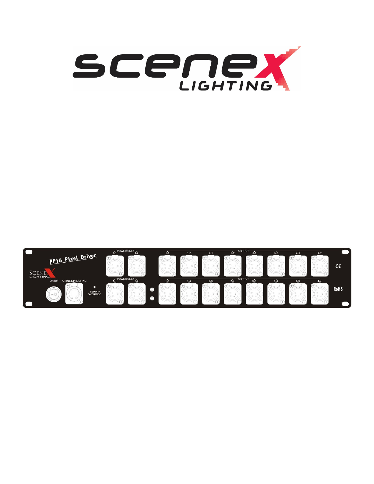
Scenex Lighting PP16 LED Driver
• 16 output ports utilize data and power via standard 4 pin XLR connectors
• Supported pixels include: LPD6803 LPD880X WS2801 WS2811 TLS3001 1903 9813
• Power output: 5V DC / 160 Amp output
• Power input: 100 – 240VAC 50/60 Hz
• 4 additional power injection ports
• Durable steel casing
• IP22 rating
• 2 U Rack Mount
• Dimensions: 3.5 in x 17.25 in x 16 in / 90 mm x 440 mm x 408 mm
• Weight: 22 lbs. / 10 kg
• 4 x 10mm threaded mounting points for clamp attachment for truss
• Forced air cooling
• Operating temperature: 32-104°F / 0-40°C
Scenex Lighting www.scenexlighting.com
XLR PIN OUT for PP16 Driver
XLR Pin # Function
1 Ground
2 Clock
3 Data
4 5 Volts DC
XLR Pin Out for PP16 Driver to Scenex Lighting Pixel Tape
XLR Pin # Tape Wire Function Tape Type
1 Yellow Ground WS2801/WS2811
2 Blue Clock WS2801 only
3 Green Data WS2801/WS2811
4 Red 5 Volts DC WS2801/WS2811
The next test will allow you to access the PP16’s web page. This is essential in order to be able to configure
the many options of the PP16.
The PP16 is a network device. It needs to be attached in one of 2 ways. If you have a ‘wired’ Ethernet network the
PP16 is usually attached to an unused Ethernet port on a network router or switch. If your PC uses wireless networking
(nothing plugged into the PC’s Ethernet jack) you will probably use a direct Ethernet connection from the PP16 to the
Ethernet jack on your PC. In either case any standard CAT5 or CAT6 Ethernet cable will work it does not have to be a
‘crossover’ cable.
Every Ethernet device has an IP address which is used to enable communication between the various devices on the
network. IP addresses are usually assigned automatically almost always by your router. IP addresses may also be set
manually this is known as a STATIC IP address. The PP16 ALWAYS uses a static IP address.
Each network encompasses a range of IP addresses. IP addresses are ALWAYS shown in the format a.b.c.d where a b c
and d are numbers ranging from 0 to 255.
In order for your PC to be able to access the web page of the PP16 the PP16 must have an IP address that lies within the
range of addresses used by your network.
Most small network have IP addresses of the form 192.168.X.Y. X will be the same for all devices on the network but Y
will be different. The most common value for X is ‘1’. In some cases it can be another value with ‘0’ and ‘2’ being the
next most common.
Since ‘1’ is the most common X value in small networks the PP16 ships with a default IP address of 192.168.1.206. For
many small networks this address will work “out of the box” and need not be changed.
One exception is if your PC uses a wireless network connection. In this case the wired Ethernet jack on the PC will
typically have an address such as 169.254.X.Y.

Scenex Lighting www.scenexlighting.com
You will need to follow the procedure below that applies to your network.
#1) You use a WIRED network, and the Ethernet jack on your PC connects to your router or to an Ethernet switch.
In this case the PP16 should connect to an unused port on your router and will need to have an IP address that matches
the address range of your network. Since the 192.168.1.X network is so common it’s often easiest just to try it and see
if it works:
Plug an Ethernet cable from the PP16 to an unused router LAN port.
Apply power to the PP16 (no pixels needed for this). After a few seconds all 5 LEDs should be lit green may be
flickering.
Open your web browser and type 192.168.1.206 into the address bar (where you see the http://www-type entries) then
press ENTER.
If you see a web page pop up that says SanDevices PP16 at the top you are in business and can move ahead to the
“configuration” section. If not the most likely cause is that your network uses something other than 192.168.1.X
addresses.
The first step is to determine which IP address range your network uses then we will use the Over-Ride function to force
the PP16 to use an address in that range.
To determine the IP address range of your network do the following:
Press the WINDOWS key to bring up the START menu.
In the command box (may say search programs and files) type CMD then press ENTER.
This should cause a black window to open. Type this into the black window:
Ipconfig /all (that’s i-p-c-o-n-f-i-g (one word) SPACE then forward slash(/) then the word all) then press ENTER.
This will display a bunch of text in the black window. Use the right-side scroll bar to scroll up to the top. Look for a
section called “Ethernet adapter Local Area Connection”. A few lines below that look for a line labelled IP Address or
Ipv4 Address. To the right you will see a number of the form (usually): 192.168. (then 2 more numbers). The first of
those “2 more numbers” is the one we are interested in. For example if you see 192.168.0.101 the number we’re
looking for is the 0.
Now we are going to force the PP16’s IP address to be in the range of your network. Take the number from above
(usually 0 or 2 thru 10 if it was a 1 the first method we tried should have worked) and add 5 to it. This is the override
number that we will use. Do an Override (described a few pages ahead as Using the Override unction) using that
override number (should be 5, or 7 to 15).
After you do this the PP16 will (temporarily) have an IP address that is within the range of your network and has a last
number of 206. (note: replace the X in this example with your network number that you got from the black screen
above ie 0 2 etc). Open the web browser and type in an address of 192.168.X.206 where X is the 3
rd
portion of your
PC’s IP address as determined above. For example if the “ipconfig” procedure showed that your PC had an address of
192.168.0.101 then the 3
rd
digit is 0 you would have used override 5 and you would now type in 192.168.0.206 in your
browser’s address bar then press ENTER.
Now do you see the PP16’s web page? If so success please jump ahead to Configuring if not please re-read and repeat
the instructions in this section.

Scenex Lighting www.scenexlighting.com
#2) You use a wireless network for your internet connection, and the Ethernet jack on your PC is not used.
In this case you will connect the PP16 directly to your PC’s Ethernet jack using an Ethernet cable. Typically an unused
PC Ethernet port will be given an IP address of 169.254.X.Y when Windows starts. Therefore we will use an Override to
force the PP16’s IP address to be within this range. Perform the OVERRIDE function (described below) using an override
code of 4.
Now go back to the browser address bar and type this in: 169.254.74.73 and press ENTER.
Do you see the PP16’s web page? If so success please jump ahead to Configuring if not please re-read and repeat the
instructions in this section.
Using the OVERRIDE function
Read this procedure through completely before doing it. You will need to know the OVERRIDE NUMBER that you want
to perform generally 1 thru 15:
1) Press and hold the TEMP IP OVERRIDE Button on the front of PP16.
2) After a few seconds the red and green LEDs will begin flashing on and off together at the rate of about 1 flash
per second. Wait until the LEDs flash the number of times equal to your override number then release the
TEMP IP OVERRIDE Button.
Example: If your override number is 5 press and hold PROG and count the flashes. When the LEDs come on for the 5
th
time release PROG.
This is a list of all override numbers and their purposes:
1Display the PP16’s currently stored IP address on the LEDs repeat until powered off.
2Force a temporary IP address of 2.2.2.2.
3Force a temporary IP address of 10.10.10.10
4Force a temporary IP address of 169.254.74.73
5Force a temporary IP address of 192.168.0.206
6Force a temporary IP address of 192.168.1.206…..
Overrides 7 through 15 operate similarly to 5 and 6 in that they force an IP address of 192.168.X.206 where X is the
override number-5.
Note: The IP address created by the over-ride is temporary. Once you are able to access the controller’s web page
change the IP address to an address that is within the range of your LAN and save it by clicking Update System
Information then restart the controller.
Use over-ride code 1 to determine the IP address of the controller when it is not known. Press and hold the TEMP IP
OVERRIDE Button until the red and green LEDs come on together for the first time then release (over-ride 1). The LEDs
will now display the current IP address. For each digit the green LED will come on then the red LED will flash a number
of times corresponding to the value of that digit. Then the green LED will go off. This process repeats until all 12 digits
of the IP address have been displayed and the entire process repeats continuously until the controller is restarted by
pressing the TEMP IP OVERRIDE again by pressing the RESET buttons (for boards that have a RESET button) or by
interrupting power to the controller. For the factory default IP address of 192.168.1.206 you would see the following
pattern on the LEDs:

Scenex Lighting www.scenexlighting.com
Brief pause with both LEDs off then green ON then red flashes 1 time then green off (1)
Brief pause with both LEDs off then green on then red flashes 9 times then green off (9)
Brief pause with both LEDs off then green on then red flashes 2 times then green off (2)
(slightly longer pause then next group begins)
Once the current IP address is known (factory default is 192.168.1.206) if it is within the address range of your LAN just
enter that IP address in your browser’s address bar. If it is outside of the range of your LAN use the override procedure
described above.

Scenex Lighting www.scenexlighting.com
Configuring the PP16 to operate with your pixels:
Once you have successfully connected to the PP16’s web page (possibly using an override) you should see a web page
similar to this:
In general you will make configuration changes by entering the desired value(s) using entry boxes checkboxes buttons
and drop-down lists. Then you will click the corresponding UPDATE button for the changes to take effect. Please note
that there are several UPDATE buttons; when you make changes in one area of the screen, you must press the proper
UPDATE button, before moving on to make changes in another area. In particular each pixel output group has its own
configuration line and its own UPDATE button. So when configuring outputs you would make all changes to output
group 1 then click that line’s UPDATE button. Then move on to output group 2 and repeat the procedure.
The web page is divided into 3 main sections: System Information Universe Selection and Output Configuration.
System Information
The System Information section allows the user to view and/or change the following system settings:
IP Address: This is the IP address that the controller will have when it is not over-ridden at startup. This IP address is
used to access this web page and is also used as the destination address if using E1.31 Unicast mode or Art-Net
(described later). The IP address is entered as 4 separate numeric values. The controllers are shipped with a default
address of 192.168.1.206. If you LAN uses 192.168.1.x addressing you should be able to access the controller simply by
entering that IP address into the URL bar of your browser. If your LAN uses a different address range there is an over-
Scenex Lighting www.scenexlighting.com
ride mechanism described earlier in this manual that allows you to use the Temp IP Overide Button on the controller to
force a different IP address at startup. Typically this is used to force an IP address in the range of your LAN then you can
access the web page and change the IP address so that is within the address range of your LAN. To change the IP
address simply click on all of the 4 IP address boxes and enter the desired values. When finished you must click the
Update System Information button to save your changes. In order for the new IP address to take effect you must then
restart the controller by pressing the RESTART CONTROLLER button at the lower left. Note that ONLY an IP address
change requires a restart all other changes take effect immediately when the corresponding UPDATE button is pressed.
If you used the override procedure to access the controller’s web page
you should change the IP
address now to one that is compatible with your network so that you can access the controller in the future without
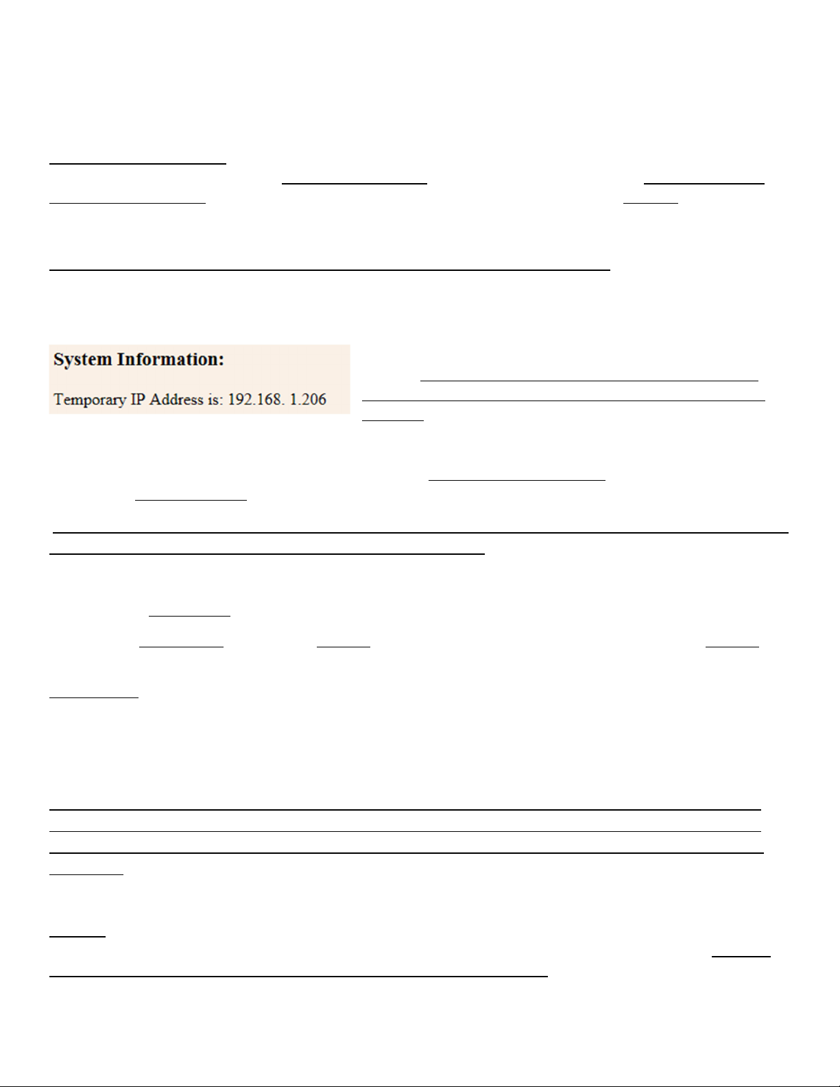
using the override. If an override was used you will see a line at the top of the screen that shows the temporary IP
address that is in use because of the override:
In many cases this will be a good choice for the permanent IP
address. You would want to use a different address if your LAN
already has another device at this address, such as another pixel
controller. In general if that is the case just use the next
consecutive address. If you have 3 PP16s for example the first one can be 192.168.1.206 the 2
nd
can be 192.168.1.207
etc. Enter the 4 parts of the desired IP address into the 4 IP Address boxes. Verify that all parts of the IP address have
been entered correctly. Once they are all correct click on the Update System Information button. Wait a few seconds
then click the Restart Controller button.
Wait a few more seconds until both LEDs come back on, then you should be able to type the new IP address
into your browser to regain access to the controller’s web page.
Once the IP has been set or if you don’t need to change the IP address continue here:
The controller’s Subnet Mask is shown next. This is set automatically by the controller based on the IP address in use.
The controller MAC Address and controller Up-Time items are display only items and cannot be changed. Up-Time
simply shows the elapsed time since the controller was last restarted.
Receive Mode Receive Mode is an item that can be changed by clicking on the appropriate button to change the
receive mode from Unicast E1.31 to Multicast E1.31 or Art-Net. At this time Art-Net support is limited to reception of
ArtDMX packets directed on the controller’s IP address. ArtPollReplys and broadcast Art-Net packets are not
supported. In general it is suggested to use Multicast E1.31 as your first choice. The other modes are more specialized
and will be described later.
IMPORTANT NOTE RE IRMWARE VERSION 4.026: There are known bugs in the Art-Net implementation
with firmware versions prior to 4.033. If you are running version 4.026 please do NOT select the Art-Net
Mode. If you need Art-Net and have a firmware version earlier than 4.033 please contact SanDevices for
assistance.
Timeout may be set to any value in the range of 0 or 2-99. If non-zero and if incoming data stops all of the controller
outputs will be turned off after the selected number of seconds of delay. If set to 0 this feature is disabled. There is a
known issue with 4.033 firmware that will cause pixel flicker if timeout is set to 1.

Scenex Lighting www.scenexlighting.com
Test A test pattern may be enabled by setting a value greater than 0. A value of 0 disables test patterns a non-zero
value enables a test pattern.
When test patterns are enabled the controller will not display any
received data.
When test patterns are enabled the web page will take longer (in some cases several seconds longer) to render, so it
is suggested to keep test pattern turned off while working with the web page.
Test Patterns: 1-3 All pixels lit RED GREEN or BLUE respectively
4-6 A bright pixel chases from start to end leaving dim pixels behind RED GREEN and BLUE
7-10 Not presently used
11-29 A pattern of n RED pixels followed by n GREEN pixels followed by n BLUE pixels that chases
through the entire range of pixels where n is the test pattern number – 10. or example, test pattern
15 is a group of 5 pixels of each color (15-10=5).
(Please note that the colors you observe may be different than those listed, this simply means that your pixels don’t
use the standard R->G->B color order. Not to worry, this can be fixed later.)
Gamma Value may be set to any value in the range of 1.0 (no correction) to 3.0 (maximum correction) in increments of
0.2. Gamma correction is used to improve the dimming characteristics of some pixel types to make them have a more
natural-looking dimming characteristic more gradual at the low end similar to the dimming characteristics of
incandescent bulbs. Gamma correction is ALWAYS applied to pixel type TLS3001 and will also be applied to 8-bit pixels
if the string length is 55 or less. To disable gamma correction set the value to 1.0.
After making any changes to any items in the System Information area you must click the Update System Information
button for the changes to take effect. With the exception of a change to the IP address, all changes become effective
immediately and do not require a restart of the controller.
Universe Selection and Packet Statistics
This area is where you define the list of universes that the controller will respond to. The set of universes needed will
depend on how your pixels or other devices are defined in the software package that sends out the E1.31 packets. This
could be LOR LightShowPro Madrix etc. Later in this manual there will be a discussion that explains many of these
terms, and talks about the design of a pixel system. If you’re new to pixels, you can skip over the information here
that you’re not familiar with, and then after reading the material later in the manual you will have a better
understanding of how these configuration settings work.
Based on the settings that you use to address your pixels in your sequencing software you will know how many
universes and which universes need to be received by this controller. Typically the universe numbers are entered in
order from lowest to highest. Unused universes should be set to a value other than 0 that does not duplicate any other
universe number. Valid universe numbers are 1-63998. There should be no duplications in the universe numbers used
in other words don’t enter any one universe number into more than one box. Universe numbers are entered simply by
clicking on the appropriate entry box and entering the desired value. When finished click the Update Universe
Numbers button to save the changes. Universe number changes become effective immediately. Note that the
selections here simply determine which set of incoming universes the controller will receive. In the next section we
will assign those universes to control specific pixel strings.
Scenex Lighting www.scenexlighting.com
This section of the page contains 3 additional items of information for each universe: Packets Received, Sequence
Errors and Invalid Packets. These are display-only items. Packets Received lists the total number of packets received
for this universe since the controller was restarted. Sequence Errors shows the number of packets that were missed or
skipped over. Typically this value will be rather small but not necessarily 0. For example the controller will tend to miss
some incoming packets when the web page is being updated although this is typically not visible because the packets
come in so quickly. Invalid Packets indicates the count of packets that were not proper E1.31/SACN packets. This
should rarely have a non-zero value.
Important: The first 7 universes can be used for pixel control data of any type: Multicast E1.31, Unicast E1.31, or Art-
Net. The last 5 universes cannot be used for Multicast E1.31. If you use Multicast E1.31 you must only assign the 1
st
seven universes to your pixel strings (see Output Configuration, below).
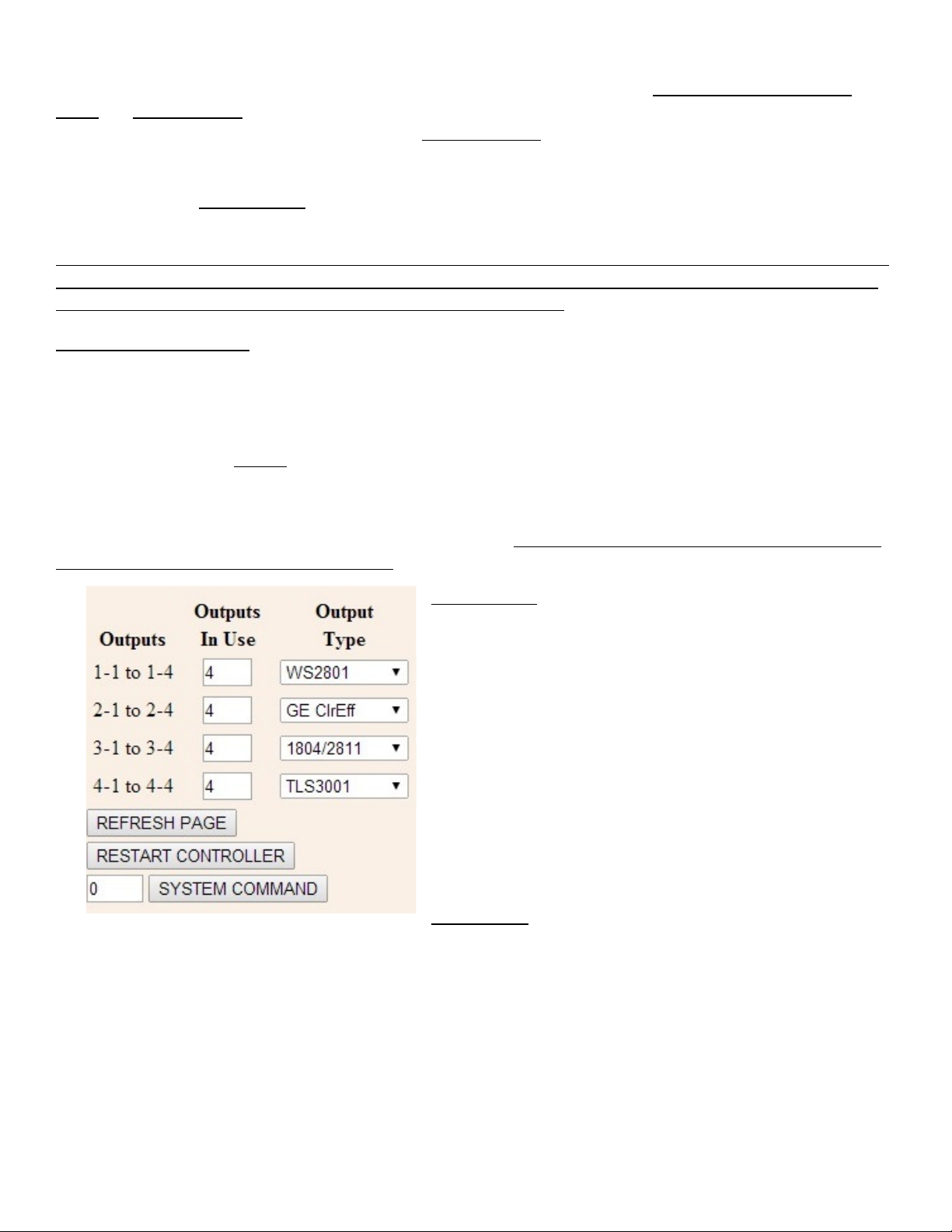
Output Configuration
Many of the pixel configuration options of the PP16 are configured in groups of 4 outputs, or “output groups”.
This is where the individual controller output groups are configured. Output groups are labeled 1 through 4 matching
the numbers on the PP16 itself. In other words Output Group 1 consists of the 4 outputs labelled 1-1 thru 1-4. Each
output group has its own Update button which must be clicked for the changes to be saved and to take effect. Changes
take effect immediately when the Update button is clicked no controller restart is needed.
Remember that changes will not take effect until the appropriate Update button is clicked and will not be saved if a
different Update button is clicked. So when configuring outputs configure all of the items for one output group then
click that Update button to save those changes. Then move on to the next output group and repeat the procedure.
Outputs In Use This is the number of outputs (0 thru 4) that is in
use in this output group. Outputs that are marked as in use will
be assigned a range of DMX addresses if the specified Length in
Pixels is greater than 0. This value should reflect the actual
number of pixel outputs in this group that will be used and
outputs must be used beginning with the first output in the group.
In other words if outputs in use is set to 2 for output group 3 it
means that outputs 3-1 and 3-2 will be used but 3-3 and 3-4 will
not.
Output Type is a drop-down selection list that allows you to
choose the type of pixel (or other device) attached to this output group (all outputs within an output group will have the
same pixel type). As of this time the following pixel types are supported: 6803 2801 GE Color Effects 1804/2811
16716 880x 981x and 3001. Non-pixel output types supported are Renard (57.6kbps) and DMX.
Scenex Lighting www.scenexlighting.com
Length in Pixels is where you enter the number of pixels that make up the pixel string or strip connected to this output
group. For output types Renard or DMX, the value entered here would be the number of channels of output desired
divided by 3 since each ‘pixel’ uses three channels. As an example for a full universe of DMX output (actually 510
channels) you would specify a length of 170. This is because 170 pixels would use 510 channels.
If you connect strings of different lengths to an output group set the Length in Pixels based on the size of the longest
string. In general it is most efficient to keep the strings in an output group as similarly-sized as possible.
Group Size allows pixels to be controlled in groups rather than individually. This feature would typically be used either
to reduce the number of channels needed or to simplify programming of the pixels. When the group size is other than 1
instead of pixels being controlled individually groups of pixels are controlled. For example with a string length of 50
pixels and a group size of 5 the string would be controlled as 10 groups of 5 pixels and would use only 30 channels
(10x3) instead of 150 channels (50x3).
Color Order is a drop-down that allows the specific color order of the pixels connected to this output to be specified.
This can be helpful if the particular pixel string or strip does not use the standard R->G->B color order. If the pixels do
not light with the expected colors because they use a color order other than RGB changing the color order to the proper
sequence (often by trial and error) will correct the problem.
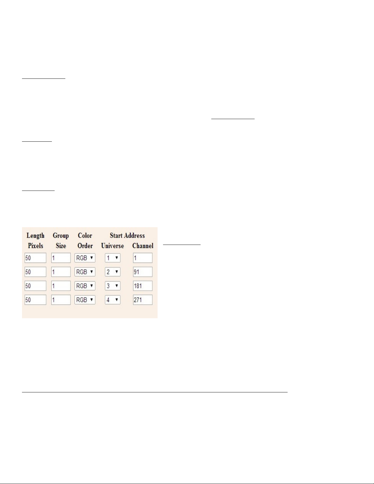
Start Address Each output group that is marked as in use and has a
length greater than 0 is assigned a sequential block of DMX
addresses. The length of this address block is (Length in Pixels) X 3 X
(Number of Outputs In Use) because each pixel requires 3 channels
one for each of its primary colors; red green and blue. Note that if
pixel grouping is used the number of channels needed will be
reduced accordingly.
The operator can configure the starting address for each output
group. All pixels on that output group are then assigned consecutive
addresses beginning with the specified start address. The necessary channels may span across one or more universe
boundaries depending on the start address and the number of channels needed. When the end of a universe is reached
(channel 510 is the last channel used in each universe) channels will be assigned from the next selected universe based
on the order of universe selection (see Universe Selection and packet Statistics).
In most cases the selected universes will be assigned sequentially. For the first controller the starting universe will often
be Universe 1. If using Multicast for example the first controller would typically be configured for universes 1 through 7.
If a different group of universes is selected, this will affect how channel addresses are assigned. For example assume
that the first 5 selected universes (from left to right) are 1 3 5 7 and 9 (not typical but possible to do). If we define
output group 1 as having 200 pixels with 2 outputs in use then this output needs 1200 total channels (200X2X3).
Assume that we start this output at Universe 1 Channel 1. Since there are only 510 useable channels per universe the
next 510 channels will be assigned from Universe 3 since Universe 3 follows Universe 1 in the universe selection list and
the last 180 channels will be assigned to universe 5 since it follows universe 3 in the universe list.
Scenex Lighting www.scenexlighting.com
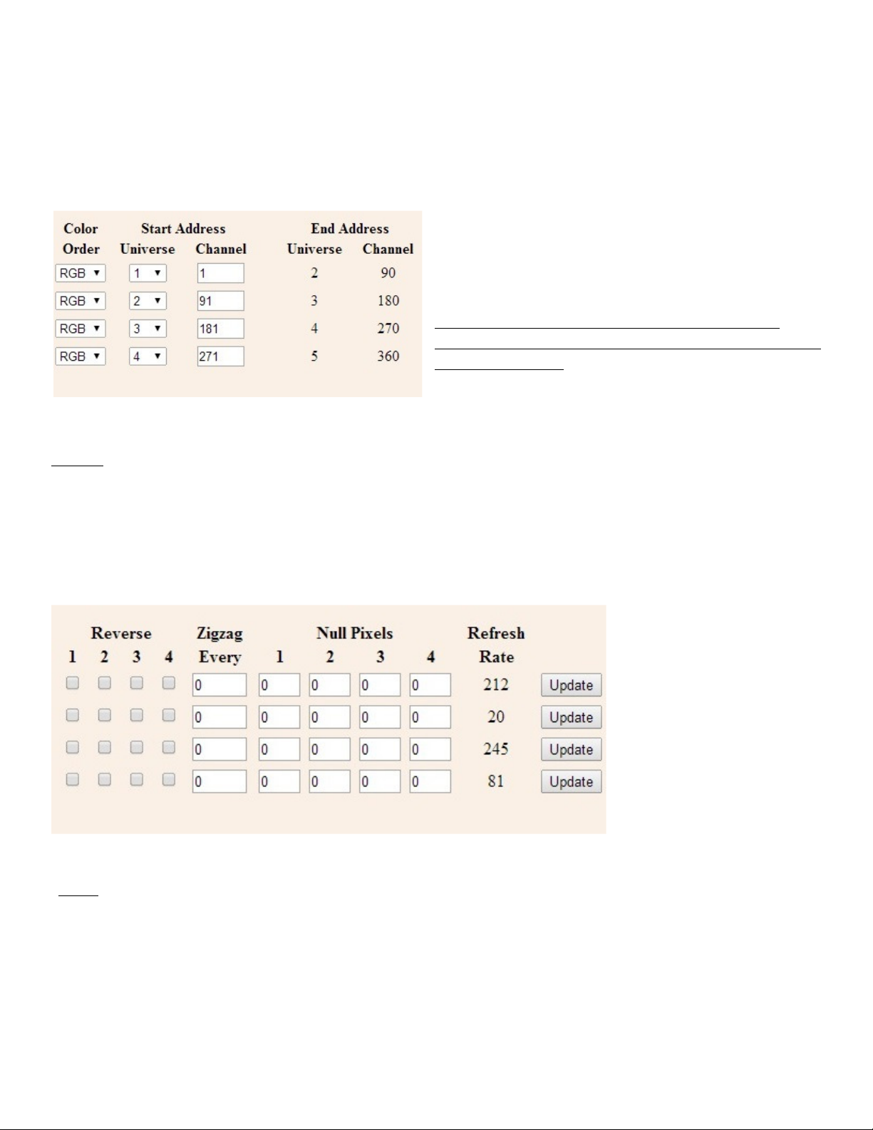
The selection of the start address for an output is done by entering the starting Universe (from a drop down list which
will only show the list of available universes) and a starting channel a numeric entry from 1 through 508.
Although not specifically required it’s best to start every output on a channel number of 1 or 1 plus a multiple of 3 (4 7
10…508). The example below reflects the selected universe group consisting of universes 5 through 16.
You can see in this example that a starting address of Universe 5 Channel 1 produced an ending address of Universe 6
(the next universe in line) channel 90. This is because the
output needs 600 total channels 510 from Universe 5 and
90 from Universe 6. The ending channel is calculated
automatically by the controller only the starting address
can be entered.
Note: Start Address and End Address values are NOT
displayed for any output group that has no outputs in use ,
or has a length of 0.
Reverse The Reverse check-boxes allow you to indicate that the associated string is ‘backwards’ in other words the first
pixel to light will actually be the last pixel of the string. An example where this feature would be useful is a roofline
where the controller is mounted at the mid-point with one pixel string (say #1) running to the left and another (say #2)
to the right. Without the reverse feature if you began lighting pixels in order you would actually be lighting pixels
beginning at the center of the roof working left to the left end then jumping back to the center and then working to the
right. By selecting the check-box to indicate that the first string is reversed the pixel sequence will be as it should be
from left to right with no jumps.
Zigzag The Zigzag feature is another feature that can simplify the pixel programming by allowing the pixel addresses to
flow in a more logical order. As an example say you have a matrix of 200 pixels arranged in 20 columns of 10 pixels. If
you start at the bottom left you would string pixels 1-10 from bottom to top in the first column and then pixels 11-20
from top to bottom in the 2
nd
column and so on basically zig-zagging up and down. When done if you lit pixels in order
from the lowest address to the highest you would see a pattern that started at the lower left and zig-zagged up and
down across the matrix. When programming the pixels it’s often easier if the pixels light in a more natural order. In this
example we would use the zigzag feature to tell the controller that the pixels reverse direction every 10 pixels. Now

Scenex Lighting www.scenexlighting.com
lighting sequential pixels produces the desired effect the first column lights from bottom to top then the 2
nd
column
from bottom to top etc.
Null Pixels Null pixels are pixels which are ignored by the controller and never lit. The most common use of null pixels is
to allow a longer length of wiring between the controller and the start of as pixel string. Because the pixel control
signals aren’t designed to travel over long distances it may not be possible to use wire runs longer than about 20 feet. If
the particular installation requires a longer wire run than normal this can often be accomplished by inserting one or
more extra pixels in the wire run between the controller and the pixel string. Each of these pixels will regenerate the
control signals enabling them to be run for another 20 feet or so. As an example if we needed to have a 100 foot wire
run between the controller and a pixel string we might use 4 null pixels one at 20 feet 40 feet 60 feet and 80 feet.
Even though the total run was 100 feet the maximum distance between pixels is only 20 feet because of the null pixels.
Another use for null pixels is when you don’t need the full length of your string. Say you have a 50-pixel string but only
need 48 pixels lit. If it’s more convenient to have the unused pixels at the start of the string rather than at the end set
the string length to 48 at set null pixels to 2.
Refresh Rate This is a displayed value that shows the approximate refresh rate of the pixels connected to this output. It
is affected by pixel type and string length.
Special Purpose Buttons
There are 3 special buttons at the bottom of the page and one number entry box.
Refresh Page simply refreshes the page without changing any configuration. Since the web page never updates by itself
you would use the Refresh Page button for example to see updated packet statistics or updated system up-time.
Restart Controller simply does a reset of the controller the same as would happen if you removed then reapplied
power. It would most commonly be used after a change of the IP address since an IP address change does not become
effective until the controller restarts.
The System Command button is used to perform some infrequently used functions based on a numeric value that is
entered into the number box to its left. There are 3 system commands presently defined:
10 Erase system configuration memory. This will wipe out all configuration data with the exception of the IP
address.
20 Set test default configuration. This function sets all outputs for type 2801 pixels 50 pixels per string.
30 Set as-shipped defaults. This sets 4 different pixel types on the 4 outputs.
As an example to return a board to the factory default configuration (other than IP address) you would enter 10 in the
system command box and click System Command. Then enter 20 and click System Command. Then enter 30 and click
System Command.
Note: The PP16s web page is ALWAYS static, in other words it NEVER updates by itself. It will stay as-is until
you either hit refresh type in a command or hit “refresh” which is the same as re-typing the previous command.
The times and statistics shown on the page are as of the last time the page was displayed.

Scenex Lighting www.scenexlighting.com
What exactly is a Pixel, and some Pixel System Design Considerations
A pixel system is just that a system. As a minimum it consists of some sequencing software. If you’re background
includes experience with non-pixel displays you’re probably familiar with sequencing software. It’s a program usually
running on a PC where you design your “show”. Often a combination of lights and music but sometimes lights alone.
This is where you define what lights (or pixels) will be lit during different segments of your show.
If you’re familiar with sequencing software then you’re also familiar with the concept of channels. For non-pixel
displays a channel is assigned to each display element; perhaps a string of lights or a flood light or a lighted fixture such
as a star or mini-tree. The goal of every serious display designer is to have individual control over smaller and smaller
pieces of the display.
Pixels takes that concept to its ultimate level. We are no longer limited to say turning on a string of red LEDs. Now we
can not only turn each LED in the string on and off independently of the others we can set its intensity and set its color.
A pixel is in fact a multi-color LED (actually 3 tiny LEDs placed very close together one red one green and one blue).
along with some circuitry that gives it some smarts. The circuitry that makes up each pixel is able to look at a string of 1s
and 0s coming down the data wire determine which 1s and 0s belong to it and translate those 1s and 0s into any color
and any brightness level.
OK let’s back up. We discussed the sequencing software. When we add pixels we are adding a whole bunch of
channels because each and every pixel requires 3 channels one for each of its primary colors. Before pixels our
sequencing software would send out our lighting commands in several possible ways. The Light-O-Rama software is
designed primarily to control LOR controllers over an LOR network using an LOR ‘dongle’ that plugs into your show PC.
Other software might output channels in the DMX format or the Renard format again using a dongle in the PC. While
the approaches are different they are similar in many respects. In every case they use serial data a fast stream of
sequential 1s and 0s to control many output channels over a single wire. By many we are talking typically up to
hundreds of channels. DMX for example is an industry standard that allows control of up to 512 channels over a single
wire. That sounds like a lot but in terms of pixels it will only let us control up to 170 individual pixels. It’s easy to see
that a large pixel display using DMX would be a wiring nightmare.
Coming to the rescue the lighting industry defined ways to get many more channels on a single wire by using Ethernet.
Ethernet is the network standard used by all PCs it’s the familiar oversize-phone-plug cables that we call CAT5 or CAT6.
(Please note that LOR uses the same type of cable but it is NOT ethernet).
So how many channels can we send over an Ethernet cable? How about a few hundred thousand? OK so that solves
the wiring problem in two ways. Not only do we no longer need a dongle (or multiple dongles) because our PCs already
have Ethernet we also only need one Ethernet cable regardless of the number of channels we need.
What we do need though is a controller. The sequencing software has the responsibility to convert out channels to a
form that can be sent out over the Ethernet. There are 2 standards. The most common is known as SACN for Streaming
ACN and it’s also known as E1.31. The second is called Art-Net. E1.31 is the newer of the two and in general it’s easy to
implement. While Art-Net has some additional capabilities it has additional complications as well.
So our PC and our sequencing software are going to be shooting out our lighting commands as Ethernet data in the
form of packets using either E1.31 or Art-net. The concept of a packet really isn’t all that important but in simple terms
one packet carries up to 512 channels of lighting information. This by the way equates to what could be sent over one
traditional wired DMX circuit. In order to keep everything sorted out each group of up to 512 channels is called a
Scenex Lighting www.scenexlighting.com
universe. Depending on the total channel count your PC will be sending out packets for one or more universes. One
universe of E1.31 or Art-Net has the same capacity as that of a single traditional wired DMX network.
This is where the pixel controller comes in. The pixel controller’s job is to look at all of the 1s and 0s coming down the
Ethernet cable sort out which ones are lighting data sort out which universes of lighting data it needs to keep and
eventually to rearrange those 1s and 0s into several different streams to send out to the pixels. And do some crunching
along the way so that whatever pixel type is attached to the controller sees its data in the format that it needs to see it
in.
Finally we need a power supply to power the pixels and we need the pixels themselves. So the complete pixel
“system” looks like this:
Sequencing Software Ethernet Port on PC Ethernet Cable to ControllerPixel Controller-------- Pixels
Pixel Power Supply
Pixel System Design
Often it’s best to start small get your feet wet so to speak then expand your system. As a minimum you will need (in
addition to the sequencing software and PC that you probably have already) a pixel controller a power supply and at
least one string of pixels. “Playing” with a small configuration is a good way to get to really understand how all of the
pieces work together.
Eventually though you’ll be ready to design a full display. Once you have a feel for the number of pixels you will be
using and where they will be placed you can determine the number and type of pixel controllers that you will need.
For a fairly small display 4 strings or less located fairly close to each other you could use a single E6804 controller. An
PP16 can handle up to 16 strings and is often used for larger display objects such as mega-trees. If you will have multiple
pixel display elements and they are spread out you will probably want to have a pixel controller in each location to keep
the wire length between controllers and pixels as short as possible.
Keep in mind that the capacity of a single controller can be limited in several ways. There’s a limit to how many physical
strings you can plug in there may be a limit as to total power consumed by all of the pixels and there can be limits
based on the total number of pixels vs. available addresses.
You also need to choose a pixel type. There are many variations. Most common are pixel strings much light LED light
strings or pixel strips a flat flexible strip about ½” wide that has pixels embedded along its length. With pixel strips the
pixel spacing is fixed although there are typically several spacings to choose from. With pixel strings you can often have
them custom built with the spacing that you need.
In general you will need one pixel power supply per pixel controller in a voltage that matches the voltage needs of the
pixels that will be connected to that controller (almost always either 5 volts or 12 volts).
Once you have a general feel for the number and length of pixel strings and the number type and placement of
controllers you can decide how to assign addresses to your pixels.

Scenex Lighting www.scenexlighting.com
Addressing begins in the sequencing software this is where each and every pixel is assigned a group of 3 addresses. This
is of course in addition to the channel needs of your non-pixel display items. For pixels these addresses are expressed
as a universe number and a channel number. Each universe can control up to 170 pixels and to use all of them would
require 510 channels. If you have more than 170 pixels you will be using more than one universe.
The specifics of mapping pixels to channels is dependent on the sequencing software used. In general it’s easiest to
assign them sequentially. Pick a logical starting point in your display and assign the 1
st
string of pixels to begin at
universe 1 channel 1. Usually it’s easiest to just assign everything in order but you may want to leave some gaps at
points in the addressing if you know you will be adding additional pixels in the future and you will want them to have
certain addresses. In general there’s no penalty for skipping over addresses but you don’t want to go crazy and for
example assign a separate universe to every string of pixels. The reason for that is that the pixel controllers have a limit
as to how many different universes they can listen to. If you put every string of 50 pixels on its own universe and you
wanted to put 16 strings of pixels on a controller you would have a problem because a single controller can’t listen to 16
separate universes. On the other hand if you want to assign 3 50-pixel strings per universe then skip ahead to the next
universe for strings 4-6 that would be fine.
Once you have a plan in mind for assigning channels to pixels then you will have the information you need to configure
the controllers. You also need to decide which protocol you’re going to use to send the data from the PC to the pixel
controllers.
In some cases you won’t have a choice. If your sequencing software only supports Art-Net then you obviously have to
choose Art-Net. If you want to use E1.31 but your software only supports Multicast E1 31 then you will have to choose
that.
Let’s talk a bit about the 3 protocols. Art-Net and Unicast E1.31 both send their lighting packets from the PC directly to a
specific controller using the controller’s IP address. The advantage is that traffic on the network is minimized. The
disadvantages are that you have an extra step in the configuration process because the sender needs to know the IP
address to send each universe to. Also it’s usually not possible to send the same universe to more than one controller.
This might be a consideration for example if you wanted all of your pixel addresses to run contiguously without gaps.
Say one controller’s pixels end in the middle of a universe. Well to be gap-less the next controller would have to start
up in the same place and that’s not possible with a unicast protocol because each universe can only go to one
controller.
Multicast E1 31 on the other hand uses a different approach. Every data packet is sent to the entire network so the
sender doesn’t need to know the IP addresses of the pixel controllers and if necessary several pixel controllers can be
setup to respond to the same universe. The disadvantage is that there is more overall network traffic because every
lighting packet goes to every controller. This is usually not an issue unless you have a partially wireless network. A large
volume of lighting data packets can overwhelm a wi-fi channel. The other potential disadvantage of Multicast is that the
E68X controllers are not able to listen to as many Multicast universes as they are Unicast universes. This only becomes
an issue if you want to go beyond 7 universes (1190 pixels) per controller. If you do you will need Unicast E1.31 or Art-
Net.

Scenex Lighting www.scenexlighting.com
Contact Information
Scenex Lighting
1145 Arroyo Street Unit A
San Fernando
CA 91340
United States of America
www.scenexlighting.com
Tel: +1 818 767 8899
Table of contents


