USER MANUAL
WWW.VARI-LITE.COM
VL5LED WASH
4
CONNECTING POWER
Depending on the application, the luminaire’s AC input cable may require a dierent connector. If required,
install a new connector meeting your requirements using the following wire color code reference:
WIRE* CONNECTION
green Ground (earth)
white AC neutral
black AC line
*International (harmonized) standard
WARNING: DO NOT connect to three-phase service in countries with 240 volt power.
For single-phase power at 240V RMS:
CONNECTION PIN
AC neutral N
AC line L
Ground (earth) G
WARNING: It is not recommended to power any Vari-Lite luminaire from a dimmer - even in ‘NONDIM’ mode.
Dimmer and non-dim modules are not suitable sources of power because their output modifies the AC wave
form. This may work for a short time, but will eventually result in power problems, luminaire mis-operation and/
or failure and may void the luminaire’s warranty.
DMX TERMINATION CONNECTOR
A DMX termination connector is required at the last luminaire (or “far end of the line”) to prevent signal reflec-
tions. Signal reflections may cancel out the signal at certain line lengths, resulting in errors. The terminator is
also necessary for software downloads and running tests on multiple luminaires. To construct your own connec-
tor, you will need a 5-pin, male XLR connector.
NOTE: A DMX termination connector assembly is available as an accessory from Vari-Lite.
INSTALLATION PROCEDURES
HANGING THE LUMINAIRE
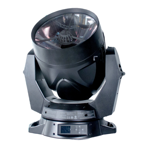
The VL5LED WASH can be hung horizontally or vertically from any structure designed to work with the type
of load created by this moving luminaire. Two mounting truss hooks or other mounting hardware are required.
Many compatible truss hooks are available from dierent manufacturers for your particular needs. A minimum
of two hooks per luminaire is required. If mounting method does not use truss
hooks, two attachment points, per luminaire, are required.
To install mounting hardware and brackets:
Step 1. Install truss hooks on two provided truss hook brackets as required.
Step 2. Determine required configuration of bracket installation. Brackets may
be installed in many dierent orientations.
Step 3. While pulling up on locking mechanism release, fit keyed holes onto
raised mounting buttons at bottom of enclosure. Slide forward and
release locking mechanism to lock in place. Ensure brackets are locked
securely.
WARNING: Ensure that the bracket locking mechanism is fully seated after
the bracket is installed on the luminaire.
FLOOR MOUNTING THE LUMINAIRE
All luminaires included in this manual are designed to sit directly on its base in a floor installation application.
When used in this type of application, be sure to leave enough space around the luminaire to allow proper, unin-
