Schaeff HT 12 User manual

HT 12 Unimog 1.96 1
1 Introduction
1.1 General
You decided to buy a Schaeff backhoe excavator HT 12.
The confidence placed in this model will be rewarded by the efficient and economical
performance of the machine.
These operating instructions contain all information necessary for the correct use of the
machine. Please read them carefully before putting the machine into operation and
make sure that they are kept at hand at all times.
Should you need further explanations or should anything be unclear, please contact
your dealer immediately.
Special equipment and attachments are not included in these operating instructions.
We reserve the right to make improvements on the machine within the scope of
impending technical developments, without incurring any obligation to change these
operating instructions.
Note
Any modifications of Schaeff products and their equipment using extras and work
attachments which are not included in our product range require our written
approval. If our approval is not sought, our warranty expires, as does our product
liability for any resulting consequential damages.
Note
The vehicle identity number of the
backhoe excavator is stamped on the
identification plate located on the slide.
Please state the machine type and the
machine identity number when making
inquiries or orders, and in all written
correspondence.
Our address :
Head Office / Sales Service Spare Parts
Karl Schaeff GmbH & Co. Karl Schaeff GmbH & Co. Schaeff Ersatzteile-Service
Maschinenfabrik Maschinenfabrik GmbH & Co.KG
Postfach 61 • D-74595 Langenburg Postfach 1264 • D-91534 Rothenburg Postfach 12 64 • D-91534 Rothenburg
Schaeffstr.8 • D-74595 Langenburg Erlbacher Str. 113 • D-91541 Rothenburg Erlbacher Straße 113 • 91541 Rothenburg
Tel. +49 7905 58-0 Tel. +49 9861 972-451 Tel. +49 9861 972-0
Fax +49 7905 58-114 Fax +49 9861 972-460 Fax +49 9861 972-410

2HT 12 Unimog 1.96
1.2 Proper use
The backhoe excavator with standard
bucket, grab or loading bucket
equipment is intended solely for work
which is suitable for the function of the
machine and its work implements.
Such work involves loosening, taking up,
transporting and dumping rock or other
materials as well as loading these
materials on conveyor belts or other
means of transport.
Any usage above and beyond that
specified here and any non-compliance
with the manufacturer’s instructions is
regarded as improper use. The
manufacturer shall not be liable for
damages resulting from improper use.
This risk is borne solely by the plant
operator.
Compliance with the operating and
maintenance instructions, the
performance of maintenance work as
specified and adherence to replacement
intervals all form part of the concept of
proper use.
1.3 Warranty and Maintenance
Safe working conditions and good
working order of the machine are
prerequisites for efficient work. Your
Schaeff backhoe excavator fulfils these
requirements when correctly handled
and when serviced and maintained as
specified.
Careful observation of the machine
whilst in function and the use of the
specified lubricants will prevent
malfunction.
Trained specialist personnel are
responsible for any servicing of the
machine which requires expert
knowledge. Inspections and repairs
must therefore be carried out by your
dealer’s customer service.
In respect of possible claims for
damages during the warranty period,
all customer service work specified in
the maintenance and inspection plan
must be carried out at the specified
intervals.
After the warranty period, too, regular
maintenance must be performed in
order to ensure that the machine is
constantly in good working order and
enjoys a reasonable service life.
Insist that only original SCHAEFF
spare parts are used in the event of
any repair work. In this way, you will
have a product of lasting high quality,
thereby ensuring that your machine
maintains its original condition.

HT 12 Unimog 1.96 3
1.4 Delivery and handing-over
instructions
The following checklist is to be
adhered to when handing over the
machine.
Operating instructions
The operating instructions should be
read side by side, and be explained in
detail through practical training on the
machine.
•Regulations for preventing accidents
published by the employer’s liability
insurance associations in the user’s
country
•Technical data
•Operational elements, control and
warning indicators
•Checks before putting the machine
into operation
•Actuation of all functions
•Explanation of maintenance and
inspection intervals according to
Maintenance and Inspection Plan by
demonstrating maintenance points on
machine
•Lubrication intervals and points of
lubrication according to lubrication
chart and demonstration of these
points on the machine
Spare parts list
•Structure of spare parts list, figures
and the respective descriptions
•Instructions for ordering spare parts:
always state the type of machine, the
vehicle identity number (Fz-Id.Nr.),
parts designation, complete spare
part number, piece number, delivery
address, etc.
Warranty
•Explanation of warranty covered by
manufacturer
•Explanation of inspection cards and
note on maintenance and inspection
plan
•Correct filling out of
warranty/handing-over card and
returning the latter to Schaeff
1.5 Notes on using the instruction
book
References to pictures and items
The references to pictures and
items contained in the text, such as
“Figure 2/4“ or (2/4) mean figure 2,
item 4 (Bild = Figure).
The figures shown in this list partly
contain additional equipment.
Attention
This danger symbol is used when
inexact compliance or non-
compliance with operating
instructions, specified work
procedures, etc. may lead to injury
or fatal accidents.
Note
This symbol is employed when
inexact compliance or non-
compliance with operating
instructions, specified work
procedures, etc. may lead to
damage to the machine. This
symbol is also used for information
which is of particular importance to
the user of the machine.

4HT 12 Unimog 1.96
2 Accident prevention
2.1 Before putting the earth-moving
machine into operation, read these
operating instructions carefully and
strictly observe the indicated references.
Note
Some of the following points are
based on the laws and regulations
valid for the Federal Republic of
Germany. This is the case for the
regulations for the prevention of
accidents mentioned in paragraph
2.2, which only apply to Germany.
For all other countries, local
regulations apply.
2.2 National safety regulations, e.g. the
Accident Prevention Regulations (UVV)
published by the employer’s liability
insurance associations in the user’s
country must be strictly observed. One
copy of the Accident Prevention
Regulations applicable for excavators,
loaders, etc. (Earth-moving machines
VBG 40), published by the “Tiefbau-
Berufsgenossenschaft“, is supplied with
the machine or can be obtained from
this organisation. We recommend
reading these regulations carefully. The
site operator and the driver of the
machine are responsible for compliance
with safety regulations.
2.3 If necessary, but at least once a
year, earth-moving machines must be
submitted to a general inspection
according to the existing UVV
regulations (Accident Prevention
Regulations). This inspection has to be
carried out by an expert (e.g. machine
engineer or machine foreman). The
results of this inspection must be
recorded in writing and this record must
be kept until the next inspection takes
place.
2.4 The operation of earth-moving
machines may only be assigned to
suitable and reliable persons of the
minimum legal age, and the site
operator or his deputy must make sure
in advance that these persons are
familiar with the operation of the
machine.
2.5 In case defects cannot be remedied
immediately, the driver of earth-moving
machines has to report any
shortcomings immediately to the
supervisor and his replacement, if there
is a change of operator. Defects which
may lead to dangers must be remedied
immediately.
2.6 Daily before commencing work and
after every change of work attachments,
the correct fastening of the work
attachments must be verified. Work
attachments are to be carefully moved
at low height.
2.7 Prior to and during work, the drivers
of earth-moving machines must ensure
that nobody who may be jeopardised is
in proximity of the machine. If
necessary, warning signals are to be
given.
2.8 Whenever they are stopped, earth-
moving machines must be reliably
secured to avoid any unintentional
movement.
2.9 It is the driver’s responsibility to
ensure that the operator’s stand and
other parts of the machine which have
to be stepped on are free of dirt, grease,
oil, ice and snow.

HT 12 Unimog 1.96 5
2.10 Only carry out maintenance and
repair work on the excavator when the
work equipment is lowered to the
ground, the engine is switched off, and
the hydraulic system is relieved of
pressure.
With the engine off, lower the work
equipment to the ground and actuate all
hydraulic control levers until there is no
pressure in the hydraulic system.
Attention
When working under the raised
work equipment, it is essential to
secure the latter by appropriate
means.
2.11 Never attempt to lift the
machine yourself or leave it in
that position for repairs.
Place pieces of wood between
the jack and the machine when
jacking up the machine. Be aware
that shifts in weight may occur.

6HT 12 Unimog 1.96
3 Technical data
3.1 Working diagram
Fig. 4

HT 12 Unimog 1.96 7
3.2 Dimensions and weights without mounting group
Dipperstick 1,500 mm 1,800 mm
Operating weight in kg
without work attachments approx. 1250 approx. 1300
Digging depth in mm 3,600 3,900
Dumping height in mm 3,200 3,200
Max. reach in mm“ 5,050 5,350
Bucket turning angle in ° 195 195
Boom slewing area in ° 185 185
Lateral parallel adjustment in mm 1,260 1,260
Total width in mm 2,000 2,000
Payload at max. reach in N 8,600 7,500
* Ripping force in N 25,000 22,000
* Breakout force in N 28,550 28,550
* Values are theoretical according to DIN 24086
Dimensions apply for standard bucket 280 - 800 mm.
3.3 Hydraulic system - Technical data
Power required for
hydraulic system 20 - 28 kW
Working pressure 175 bar
Capacity 70 - 80 l/min
Tank filling quantity approx. 54 l
Hydraulic oil temperature max. 90°C ( ΔT 60°C )

8HT 12 Unimog 1.96
3.4 Lubricant specifications
Hydraulic system: Mineral hydraulic oils
The limit values for hydraulic oils which can be used
for Schaeff construction machines and attachments
are approx. 12 mm ²/s (cSt) at 100°C and approx.
1500mm ²/s (cSt) at -10°C. See also hydraulic oil
recommendation chart for Schaeff construction
machines and attachments.
Biodegradable hydraulic oils
As an alternative to mineral oils, we recommend bio-
degradable hydraulic oils of a synthetic ester base.
The same viscosity specifications apply as for
mineral oils.
Note
When changing from mineral to biodegradable
hydraulic oils, the tank and hydraulic system must be
completely drained, cleaned and flushed.
For further details before changing oils, please
consult your Schaeff dealer.
Grease nipples: Multi-purpose grease to DIN 51825-K 2 G-40
Note
The safety data sheets of the mineral oil companies must be observed when dealing with
lubricants.
3.5 Work attachments
Width Capacity
Bucket with ejector 290 mm 0.062 m
3
Bucket with ejector 350 mm 0.072 m
3
Bucket with ejector 450 mm 0.100 m
3
Bucket 600 mm 0.164 m
3
Bucket 800 mm 0.204 m
3
Ditch-cleaning bucket 1,250 mm 0.115 m
3
Ditch-cleaning bucket 1,500 mm 0.160 m
3
Clamshell grab 350-450 mm
- Further work attachments available on request -

HT 12 Unimog 1.96 9
3.6 Other equipment
•Load hook in connection with overload warning device
•Ripper tooth
•Overhead guard
•Cab
•Widened support
- Further optional equipment available on request -
Note
Any modifications of Schaeff products and their equipment using extras and
work attachments which are not included in our product range require our
written approval. If our approval is not sought, our warranty expires, as does
our product liability for any resulting consequential damages.
10 HT 12 Unimog 1.96
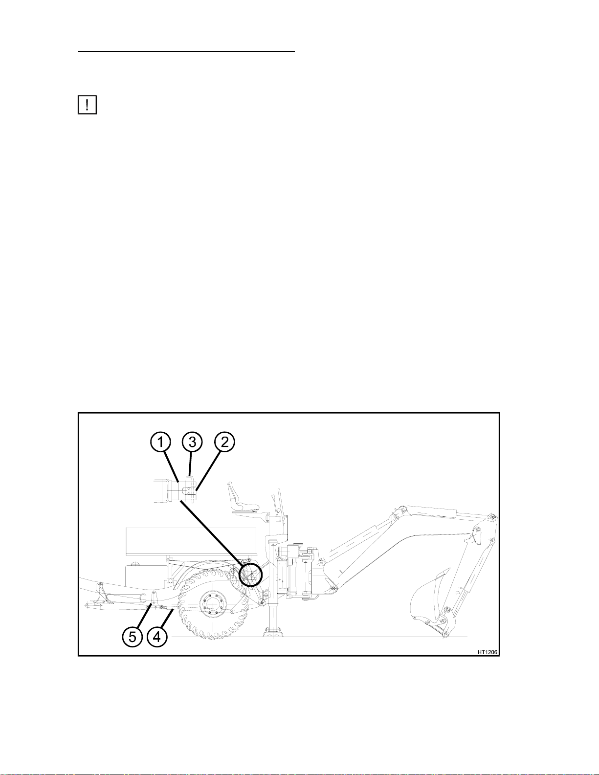
4 Mounting and dismounting instructions
4.1 Mounting
Note
The host vehicle must be equipped with the appropriate mounting group.
• The host vehicle must be driven backwards to the backhoe excavator.
• Establish hydraulic connection for excavator by connecting the hydraulic hoses to the quick
couplings.
• Connect the connection hoses of the tilt cylinder with the Unimog-connecting boxes.
• Switch on power take-off.
• Adjust the excavator with stabilisers and dipperstick to level.
• Drive host vehicle backwards and hook the backhoe excavator in slide (6/1).
• Fasten and secure the excavator using retaining blocks (6/2) and pins (6/3).
• Attach the arm (6/4) in the middle of the vehicle on the „center of the underslung frame“ (6/5).
• Bring the excavator to working position and check functions.
• The backhoe excavator is now ready for operation.
4.2 Dismounting
• Move the slide to the middle of the mounting plate.
• Place the working equipment to the ground.
• Lift the backhoe excavator by actuating the stabilisers to such a degree that the Unimog is no
longer burdened by the excavator.
• Loosen the excavator fastening (retaining blocks and arm ).
• Move the host vehicle forward so that the backhoe excavator stands free.
• Retract the stabilisers, turn off the power take-off and stop the engine.
• Loosen the hydraulic connection for the excavator and the tilt cylinders. Connect the air hose
to the return line hose on the host vehicle.
• Protect the connection hoses of the backhoe excavator from contaminations.
fig. 6
HT 12 Unimog 1.96 11
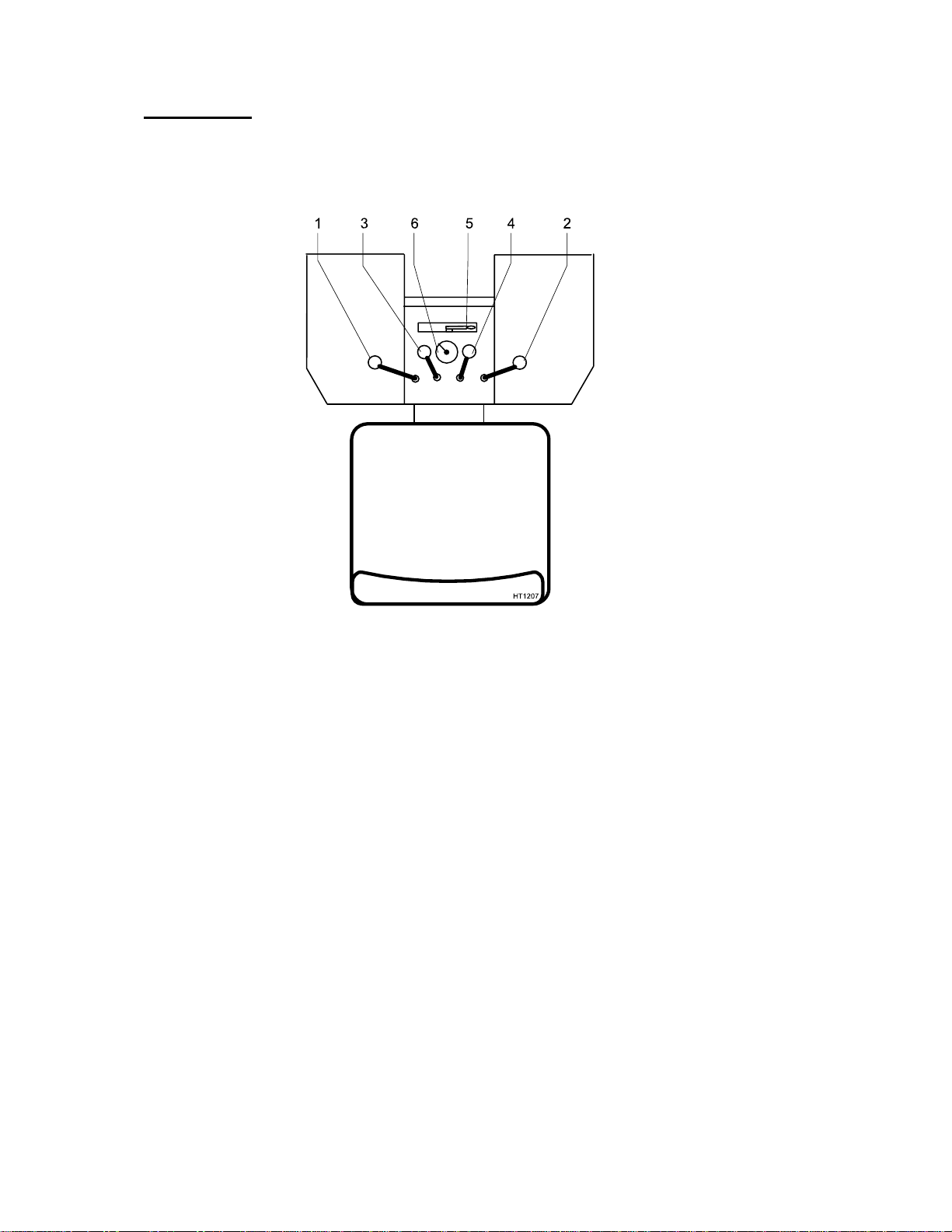
5 Operation
5.1 Operator controls
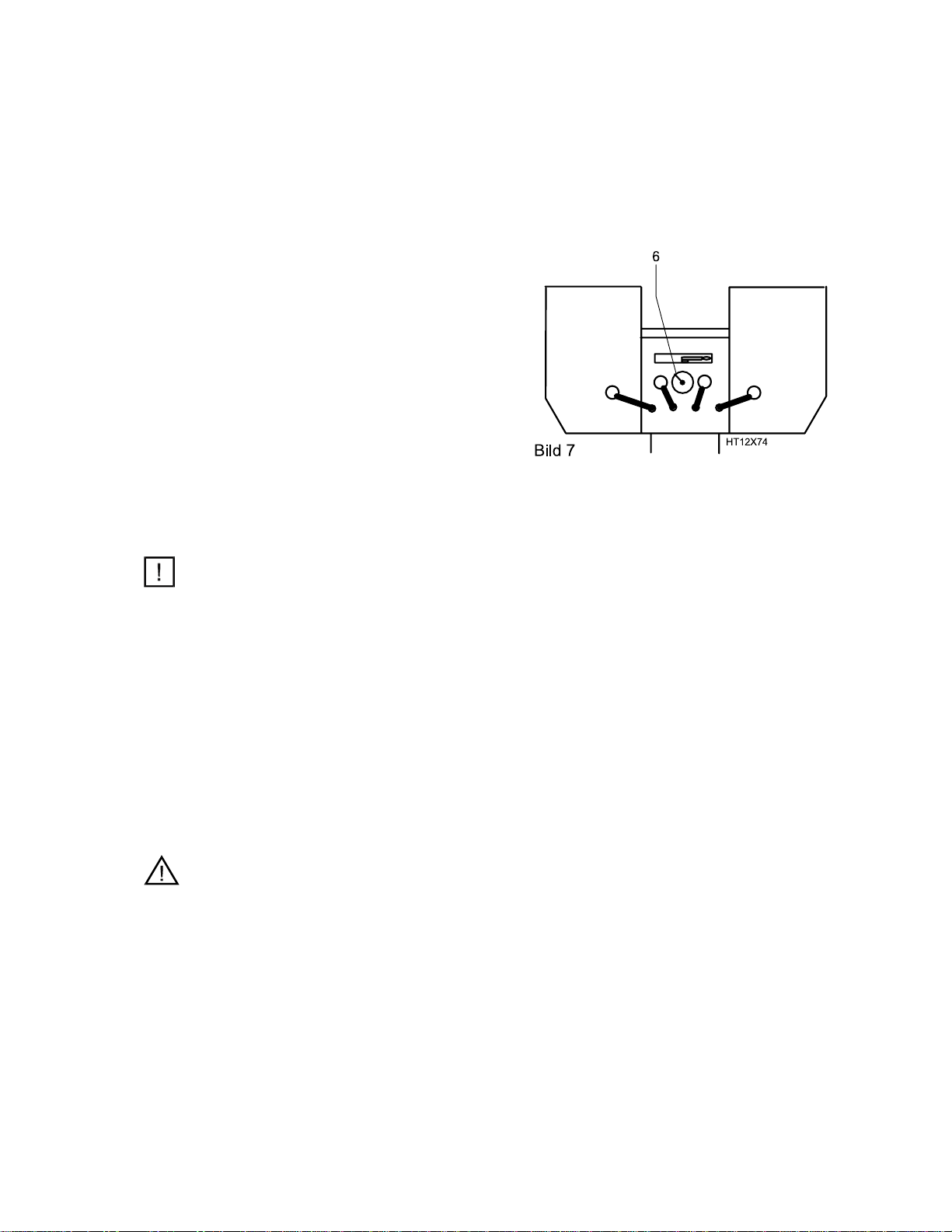
Fig. 7
1 Operator control for excavator equipment
2 Operator control for excavator equipment
3 Operator control for stabiliser, right
4 Operator control for stabiliser, left
5 Slide lock
6 Overload warning device
12 HT 12 Unimog 1.96
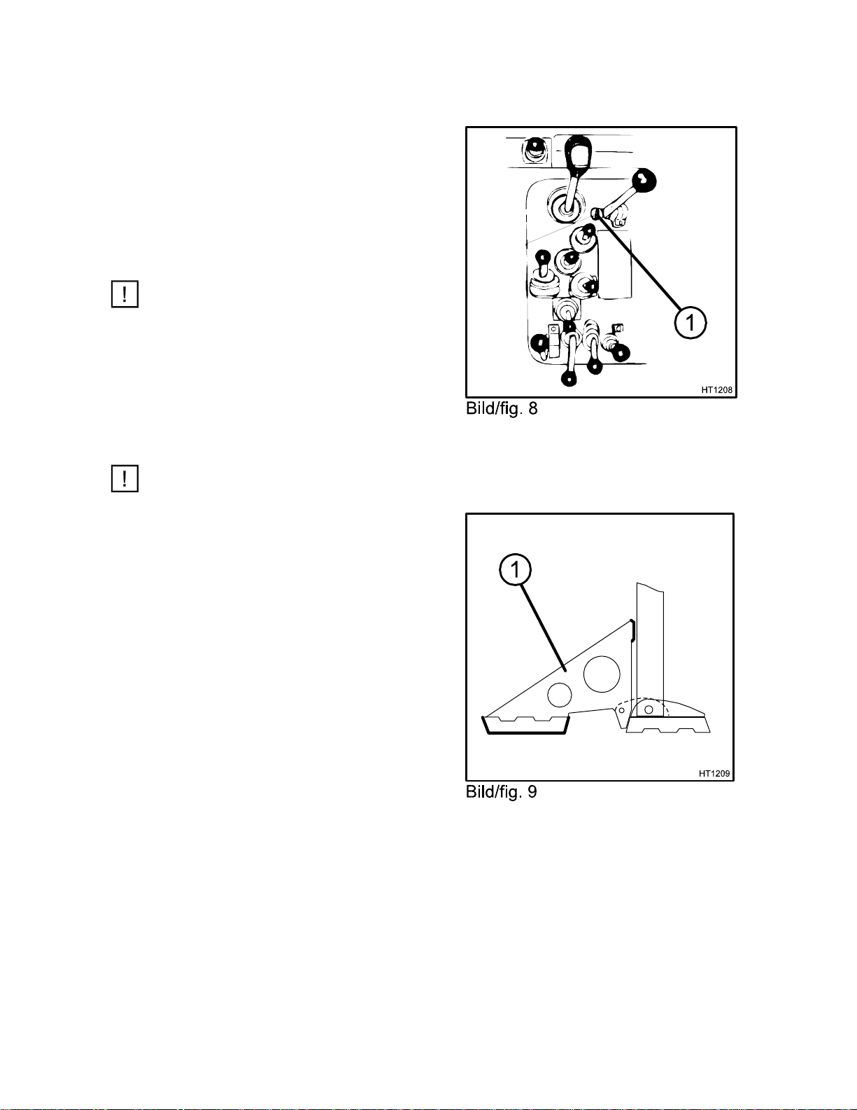
5.2 Making the backhoe excavator ready for
operation
•Start the Unimog according to the Unimog -
operating instructions and let the engine run at
idle speed.
•Lower the excavator from transport to working
position according to chapter 6.
•Switch on the power take-off (8/1) in the
operator’s cab of the Unimog.
•Increase the engine speed through external
hand adjusting lever to nominal speed of 1,550
rpm (approx. ½ gas).
Note
Only switch on power take-off during excavator
operation.
•Stabilising the backhoe excavator
•Release the parking brake of the Unimog.
•Apply the steering lock.
Note
When working with the backhoe excavator
slewed sideways we recommend employing an
additional support in order to improve the
stability of the Unimog with the HT 12 attached.
When the excavator is slewed sideways, the
additional support (9/1) on the supporting foot,
to which the excavator is slewed, must be
employed.
When driving on public roads, the additional
support must be dismounted.

HT 12 Unimog 1.96 13
5.3 Excavator operation
5.3.1 General
The excavator is equipped as standard with ISO control, upon which the following
description is based.
Attention
If the customer so wishes, the excavator may be equipped with a different control.
Your excavator must therefore be checked to see whether or not a different control
is installed. Incorrect operation may endanger persons or objects.
Before commencing work, memorise the lever controls well. Commence at low engine
speed when familiarising yourself with the controls.
5.3.2 Actuation of work equipment
5.3.3 Actuation of stabilisers
14 HT 12 Unimog 1.96
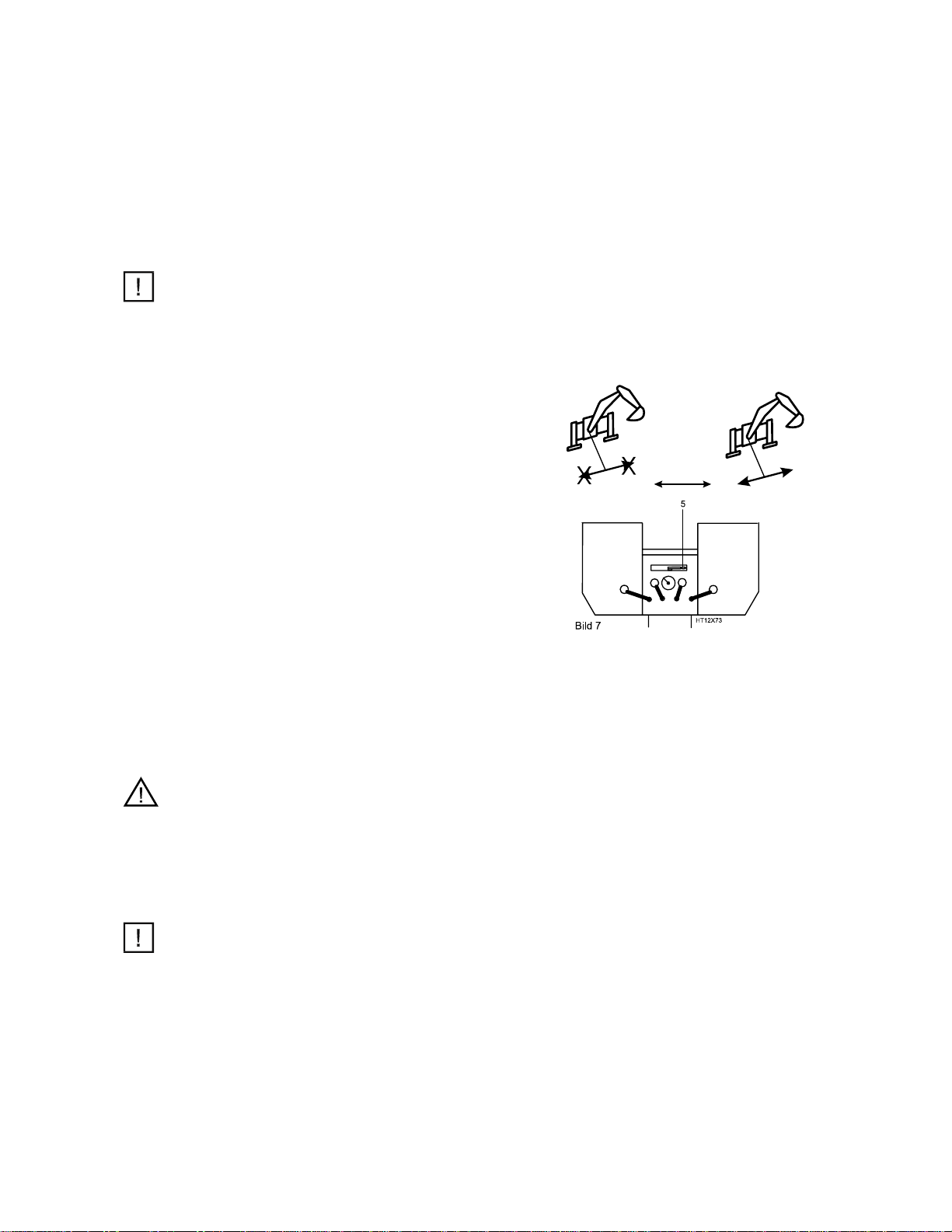
5.4 Lateral adjustment of the work equipment
5.4.1 General
The work equipment can be slewed sideways on the
mounting plate.
This allows accurate and safe work close to walls, e.g.
house walls. Furthermore, the reach of the excavator
can be increased when working across the direction of
travel.
Note
Apply the widened support if necessary.
5.4.2 Loosening and positioning the slide
To do so, the excavator is slewed in the direction of or
against the direction of slewing to the end position and
the ball valve (7/5) is opened.
After the bucket has been lowered to the ground and
the dipperstick actuated, the slide with boom is drawn or
pushed to the desired position.
5.4.3 Clamping the slide
After positioning the slide, the ball valve must be closed
and the actuating lever for „Boom up“ for pressure
build-up in the clamping cylinders must be actuated.
Thus the slide is clamped and the excavator is ready for
operation.
Attention
It is important that the machine is positioned in
exact accordance with these guidelines. Take care
to ensure that the slide is clamped in the proper
manner.
Danger of accident
Note
When working, the ball valve must always be closed
and may only be opened for lateral adjustment.
HT 12 Unimog 1.96 15
5.5 Crane operations
5.5.1 General
Crane operations are the hoisting, transporting and lowering of loads with the aid of a fixing
device (rope, chain, etc.), whereby the assistance of personnel is required to attach and release
the load.
5.5.2 Safety devices
The excavator may only be used for crane
operations when the prescribed safety devices are
present:
- Secure attachment of loading implements
- Table of carrying capacity, see section 5.5.5
- Overload warning device and a hose-rupture
safety valve if the permissible carrying capacity
exceeds 1,000kg.
The load limit is marked on the overload warning
device (7/6)
Danger starting from: 90 bar
5.5.3 Attachment of loads
Note
Loads must be attached in such a way that they cannot slip or fall out.
Possible forms of attachment
•Load hook attached instead of a bucket, etc.
•Hook with safety net welded onto the bucket rod (not possible in the case of quick-mounting
buckets with ejectors).
A suitable, appropriately sized loading implement must be employed for picking up the material
to be lifted.
Always wear protective gloves when working with loading implements.
5.5.4 Attachment and carrying of loads
Attention
Personnel guiding the machine and attaching loads must remain only in the machine
operator’s field of vision.
Personnel attaching loads may only approach the boom from the side and with the machine
operator’s permission. The machine operator may only give his permission if the machine is
standing still and the work equipment is not in motion.
The machine operator must carry loads as close to the ground as possible and prevent them
from swinging.
Machines may only travel with an attached load if the path of travel is fairly even.

16 HT 12 Unimog 1.96
5.5.5 Carrying capacities
with the following equipment:
yWithout bucket, with load hook
yBucket cylinder, rocker arm and bucket rod left on the machine
yMachine supported
Values without brackets :
All values apply for the complete slewing range and include a stability factor of 1.25.
These values are determined according to DIN 15019 page 2 and presented according
to DIN 24083.
Values in brackets :
Values correspond to the hydraulic lifting force and only apply in the longitudinal
direction (vehicle longitudinal axis) with the undercarriage supported.

HT 12 Unimog 1.96 17
5.6 Changing work attachments
5.6.1 General
In order to achieve maximum utilisation of the
machine for a variety of applications, a great
number of work attachments are available.
Attention
When the work attachments have been
removed, they must be secured against tilting
and overturning to avoid possible injuries to
persons.
Note
The hydraulic system must be relieved of
pressure before hydraulic connections are
disconnected.
5.6.2 Assembly of work attachments
Note
The bearings of the work attachment, the
dipperstick and the bucket rod must be free of
dirt.
•Procedure for changing attachments
Lower the work attachment to the ground and
position so that it cannot tilt. Remove the pins
which connect the attachment to the dipperstick
and the bucket rod.
Mount another work attachment.

18 HT 12 Unimog 1.96
6 Transport position when driving on public roads
6.1 Backhoe tilting for transport
Description to be seen in the direction of the backhoe !!
•Move the boom completely to the right and clamp. Fully retract the boom, close the bucket and
retract the dipperstick
•Slew the boom to the inside, secure the dipperstick with a turnbuckle on the mounting plate
•Apply the parking brake, release the steering lock
•Retract the stabilizers
•Fold up the driver’s seat and secure
•Position both lock pins (10/1) between the mounting frame and the mounting device in
position „unlocked“
•Ensure that the bolt (10/2) for transport lock (on the right - in backhoe direction) is in posi-tion
„unlocked“
•Tip the backhoe onto the platform by actuating the tilt cylinder via the valve lever in the Uni-
mog driver’s cab
Attention
People must not remain on the platform.
Danger of injury !
•Position the bolt (10/2) between the mounting frame and the mounting device in position
„locked“ for transport lock.
Note
Some Unimog types are equipped with lock valves for the tilt cylinder. The lock valves are
either to be opened or closed, depending upon the operation.
•Turn off the accessory drive
•Check the vehicle according to the guidelines valid in the user’s country, e.g. Regulations
Authorising the Use of Vehicles for Road Traffic (StVZO) in Germany
•Attach the protection cover for the stabilizer plates
6.2 Changing the backhoe from transport position to working position
The re-positioning is done in reverse order compared to tilting the backhoe for transport:
Attention
The valve for the tilt cylinder (valve lever in the driver’s cab of the Unimog) has to be in neu-tral
position. Ensure that the valve lever is not in floating position
•Remove the protection cover for the stabilizer plates
•Turn on the accessory drive
Note
Some Unimog types are equipped with lock valves for the tilt cylinder. The lock valves are
either to be opened or closed, depending upon the operation
•Position the pin (10/2) between the mounting frame and mounting device in position „unlocked“
•Ensure that both pins (10/1) for the backhoe lock are in position „unlocked“
•Tilt the backhoe to its working position by actuating the tilt cylinder via the valve lever in the
driver’s cab of the Unimog
Attention
People must leave the tilting and slewing area.
Danger of injury !
•Position both lock pins (10/1) between the mounting frame and mounting device in posi-tion
„locked“
•Fold down the driver’s seat and secure
•Extend the stabilizers
•Release the parking brake, apply the steering lock
•Bring the boom to its working position

HT 12 Unimog 1.96 19
fig. 10

20 HT 12 Unimog 1.96
7Care and maintenance
7.1 General notes
The good operating condition and life expectancy of machines are largely influenced by
care and maintenance.
For this reason, it is in every machine owner’s interest to perform the specified
maintenance work and comply with the service intervals. This section deals in detail
with periodic maintenance, inspection and lubricating tasks.
Furthermore, during the warranty period three thorough inspections are stipulated,
which must be carried out by trained specialist personnel.
Type-specific maintenance and inspection plans for this purpose are contained in every
instruction book and every warranty certificate.
Note
Service and wearing parts for inspections should be ordered well in advance!
Inspection intervals
1st inspection - after approx. 100 operating hours
2nd inspection - after approx. 500 operating hours
3rd inspection - after approx.1,000 operating hours
subsequently, every 500 operating hours
Note
The three inspections are obligatory and must be paid for.
If they are omitted, the warranty may be subject to restrictions.
It is essential that the recommendations in chapter 2, “Accident Prevention”, are
observed.
Table of contents
Popular Excavator manuals by other brands


Komatsu
Komatsu PC210-10 DEMOLITION BASE SPEC. Operation & maintenance manual

Hyundai
Hyundai HX140 LC Service manual

Hyundai
Hyundai HX480 L Service manual

RHINOCEROS
RHINOCEROS CTX8010 Operations & parts manual

SUNWARD
SUNWARD SWE90UF-2PB Operation & maintenance manual

Wacker Neuson
Wacker Neuson DW100 Operator's manual