GENERAL
ALPHABETICAL INDEX
A L
Air
cleaner
....................................
17,
33
Leveler,
turntable
..............................
23,
96
Alternator
.....................................
48,57
Lights
........................................
54,
65
Alternator
Belt
Adjustment
.........................
54
Lubricants
.....................................
9,
11
Attachments
....................................
148
M
B
Battery
..........................................
17
Bearing,
turntable
..............................
18,
35
Belts, fan
........................................
32
Boom
.........
,
.............................
39,
148
Brakes
Swing (house)
..............................
36,
132
Track (digging)
.............................
29,
122
Buckets
....................................
152-158
C
Cab
Insulation
....................................
9
Capacities,
Lubricants
and
Fluids
...................
11
Cold Start System
................................
63
Control
Linkages
.................................
41
Maintenance Chart
.............................
12,
13
Main Relief
Adjustment
............................
79
Motors, hydraulic
Swing
.................................
90, 186,192
Track Drive
.............................
84,
175, 178
0
Oil Cooler
.......................................
70
Oil Recommendations
.............................
10
p
Pillow
Blocks
................................
27,
129
PowerSensingValve
..........................
77,174
Pressure
Settings,
hydraulic
........................
10
Pump Drive Plate
................................
130
Pump
............
•
...........................
70,
160
R
Cooler, oil
.......................................
70
Radiator
.........................................
31
Cooling
System, engine
............................
31
Cylinders, hydraulic
..............................
203 Relief Valves
..............................
74, 79,
172
s
D
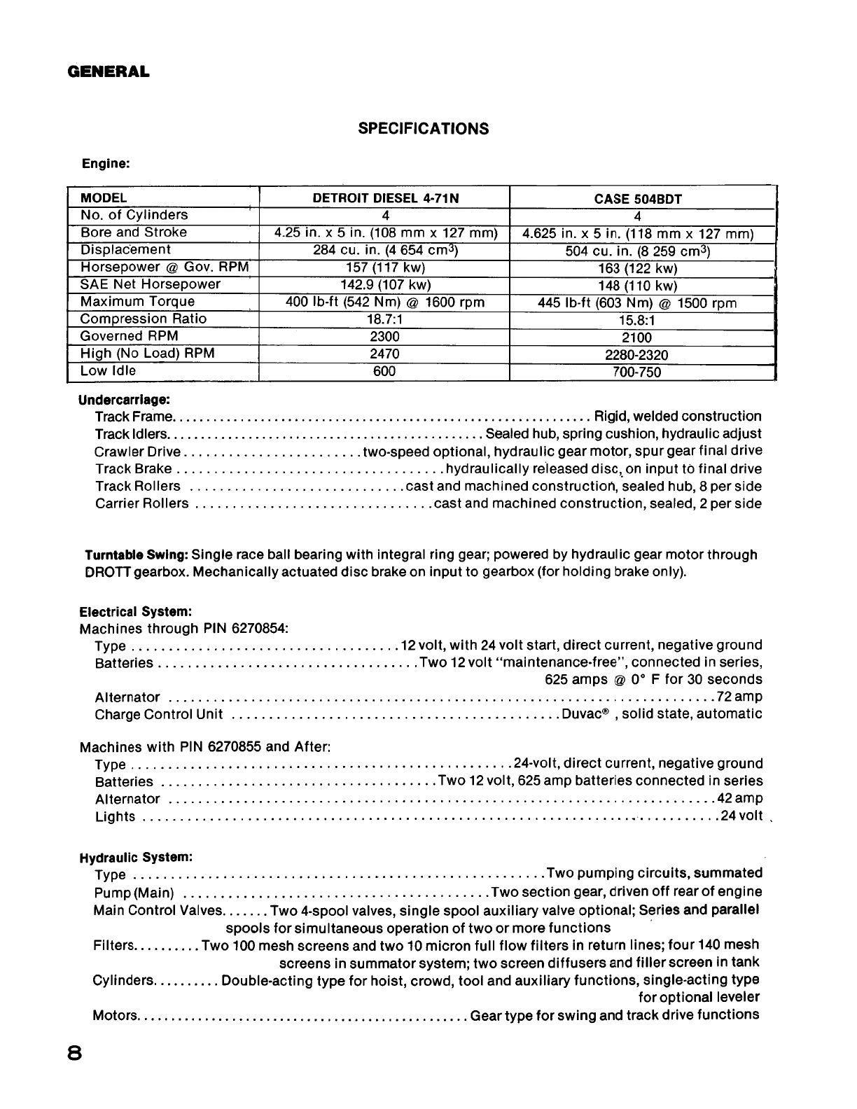
Specifications
....................................
8
Digging
Brake
................................
29,
122 Summated Hydraulics, explanation
....
.'
.............
77
Drive Locks
................................
53,
64,
86
Swing
Brake (House)
..........................
36,
132
Drive Range
................................
53,
64,
83
Swing Gearbox
............................
18,
35,
134
Drive Transmission, Final
...................
21,
27,
124
Swivel, ?-Port
................................
88,
200
E
Electrical System,
24
volt
..........................
55
Electrical System, 12/24 volt
........................
44
Engine
.......................................
16,31
F
Fast
Hoist
.................................
53,
63,
92
Filters
Air
Cleaner
..................................
17,33
Fuel
.......................................
16,
32
Hydraulic
...................................
19,
70
T
Tank, hydraulic
oil
..........................
21,
70,208
Teeth, bucket
................................
40,
156
Track
Adjustment
....................................
25
Chain
.....................................
25,
116
Final Drive
Transmission
..................
21, 28,
124
Frame
........................................
23
ldlerWheel
................................
26,
120
Roilers
....................................
23,
118
Troubleshooting
Charts
........................
97-113
G Turntable Bearing
Gauges
......................................
54,65
Alignment
of
Swing Gearbox
....................
145
Grease
Fittings
...................................
14
Capscrews,
torquing
procedure
...................
36
H
Lubrication
....................................
18
Heater, Cab
......................................
64
Hydraulic
Circuits
Crowd
........................................
94
Replacement
..................................
142
V
Valves
Hoist
.........................................
92
Drive Range
....................................
84
Leveler
........................................
96 Leveler Lock
...............................
96,
198
Main
..........................................
69 Main Control
...............................
72,
169
Swing
.........................................
90
Tool
..........................................
95 Main Relief
................................
79,173
Port Relief
.................................
74,172
Track Drive
....................................
82
PowerSensing
.............................
77,174
Hydraulic Oil Tank
.........................
21,
70,
208
Hydraulic
Swivel, ?-Port
........................
88,
200
Hydraulic System, maintenance
.....................
67
I
InnerSwivel
.....................................
83
Instruments
.....................................
65
Solenoid
Control
(Monoblock)
.................
87,
209
Swing
Cushion
.............................
90,
197
Voltage Regulator
..............................
48,
57
Voltmeter
.......................................
65
w
Wiring
Harness, replacement
......................
160
Wrist-o-Twist
...
~
................................
159
2
Find manuals at https://best-manuals.com