Schako FKF Operating instructions

SCHAKO KG
Steigstraße 25-27
D-78600 Kolbingen
Telephone +49 (0) 74 63 - 980 - 0
Fax +49 (0) 74 63 - 980 - 200
schako.com
Additional operating instructions
according to ATEX 2014/34/EU
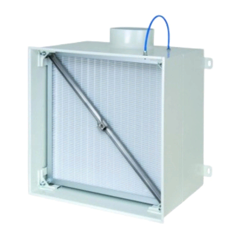
Particle Filter Box Model FKF

Contents
Construction subject to change. No return possible!
Additional operating instructions according to ATEX 2014/34/EU for FKF particle filter box
07/06 - 2 06.12.2021Version:
General conditions ...............................................................................................................................3
General description and instructions .......................................................................................................................................... 3
Personnel qualification and training ........................................................................................................................................... 3
Safety-conscious work ............................................................................................................................................................... 3
Designated use .......................................................................................................................................................................... 3
Delivery and storage .................................................................................................................................................................. 3
Mounting information ................................................................................................................................................................ 3
Maintenance ............................................................................................................................................................................... 3
Hazard caused by non-observance of the safety instructions .................................................................................................... 3
Description ........................................................................................................................................4
Models and dimensions ......................................................................................................................... 5
Dimensions ................................................................................................................................................................................ 5
Dimensions of accessories ...................................................................................................................................................... 10
Installation and maintenance ................................................................................................................. 10
Information regarding assembly and commissioning .............................................................................................................. 12
Information regarding maintenance and inspection ................................................................................................................. 12
Type plate ....................................................................................................................................... 13
Certificate of conformity ....................................................................................................................... 14

Additional operating instructions according to ATEX 2014/34/EU for FKF particle filter box
07/06 - 3
Construction subject to change. No return possible!
06.12.2021Version:
General conditions
General description and instructions
These additional operating instructions must be observed prior
to mounting and commissioning the device.
These additional operating instructions contain basic informa-
tion regarding its use in areas subject to explosion hazards to be
observed during assembly, operation and maintenance.
Prior to mounting and commissioning and during maintenance
work, the present additional operating instructions must be read
by the installer and the responsible skilled personnel/system
operator!
Personnel qualification and training
The personnel for assembly, inspection and maintenance must
have the relevant qualification for this work.
The area of responsibility, competence and monitoring of the
personnel must be exactly regulated by the system operator. If
the personnel does not have the required knowledge, it must be
trained and instructed. Moreover, the system operator must en-
sure that the contents of the additional operating instructions
are understood completely by the personnel.
Safety-conscious work
The safety instructions given in these additional operating in-
structions, the existing national and international regulations on
explosion protection, accident prevention and the system oper-
ator's internal work, operating and safety regulations must be
observed.
Designated use
The devices have been designed for use in ventilation systems
in areas subject to explosion hazards according to ATEX of Cat-
egory II, Zones 1, 2 and Category III, Zones 21, 22.
These devices are not suitable for use in unreleased Ex zones.
The operating safety of the delivered devices is only guaranteed
when used in accordance with their designated use.
Delivery and storage
Upon receipt, the devices must be checked for completeness
and transport damage. If delivered incompletely or damaged,
the forwarding company and the SCHAKO KG have to be in-
formed immediately.
The device must not be exposed directly to weather, solar radi-
ation and moisture.
Mounting information
Mounting, electrical connection work and commissioning must
be carried out by skilled personnel only and in accordance with
the recognised technical rules and the safety and accident pre-
vention regulations.
Maintenance
Only a device subjected to proper maintenance and kept in per-
fect condition can guarantee safe and reliable operation.
When defective parts are replaced with spare parts, only SCHA-
KO original spare parts may be used. The SCHAKO KG cannot
be held liable for any damage caused by using spare parts that
are not original and will not give any warranty.
Hazard caused by non-observance of the safety in-
structions
Non-observance of the safety instructions can result both in
putting persons and the environment and operating units at risk.
Likewise, non-observance of the safety instructions will result in
the loss of any claims for damages.

Additional operating instructions according to ATEX 2014/34/EU for FKF particle filter box
07/06 - 4
Construction subject to change. No return possible!
06.12.2021Version:
Description
The FKF particle filter box with fluid seal on the filter cell has
been specially developed for use in cleanrooms as required by
the pharmaceutical, electronic, precision mechanical and optical
industries in hospitals and laboratories. The integrated particle
filter (to DIN EN 1822) removes particles, radioactive dust,
mist, bacteria, viruses, etc., from the supply or return air.
This ensures that the incoming and outgoing air flows are ex-
tremely clean and germ-free.
The fluid is located at the filter cell and pressed into a sealing
device especially developed for this purpose in the filter box
when the filter cell is installed. Owing to the properties of the
fluid, the filter cell can be mounted and dismounted several
times without having to change the fluid.
The filter box, type FKF-... , consists of electrolytically galva-
nised sheet steel painted to RAL 9010 (white) or stainless steel
V2A (1.4301) with a round connection spigot for hose connec-
tion while the type FKF-Q-... has a rectangular spigot with con-
nection flange. A filter pressure device in the filter box ensures
a safe seal. As a standard feature, a differential pressure and
aerosol monitoring device is integrated in the particle filter
box.
Optionally, the particle filter boxes FKF-H-... are additionally
equipped with a shut-off damper sealing air-tight. This shut-off
damper can be adjusted manually from below after the air dif-
fuser is removed. Leakage at closed shut-off damper according
to DIN EN 1751, class 4, at a duct pressure of up to 1000 Pa. An
electric actuator is not available. As an alternative, a SCHAKO
DKA-L in ATEX version can be used outside the filter box.
Attention!
We would like to point out that we supply the filter boxes with
integrated spacers for fitting the filter clamps and the diffuser
assembly pole brace. This makes it possible to fit the air diffuser
without additional expense, even when the filter has not yet been
inserted into the filter box.
The assembly of the air diffusers is effected via magnetic fasten-
ing. This allows the air diffusers to be easily taken off for filter
replacement and decontamination without requiring tools. The
following ceiling air diffusers in supply and return air models are
suitable to be fitted to the particle filter box type FKF: FDQJ,
FPIL, FDAV. Magnetic fastening is generally not possible for
FPIL and FDAV and for air diffusers made of aluminium and
stainless steel. These air diffusers are mounted via central fas-
tening (-VM).
If required, the suitable particle filters can be included in the de-
livery.
Sealing on the particle filter
The filter boxes in stainless steel design 1.4301 are
delivered together with the air diffuser FDQJ made of stainless
steel. FPIL and FDAV are not available in connection with parti-
cle filter boxes made of stainless steel.
The particle filter box has the following ATEX marking:
This particle filter box meets the regulations of the ATEX direc-
tives and can be used in ventilation systems in areas subject to
explosion hazards.
The particle filter box has been certified for the explosion pro-
tection group II for Zones 1, 2 and 21, 22.
Zones 1 and 2 represent the application range containing gases,
while Zones 21 and 22 represent the application range contain-
ing dusts.
Classification by zone must be established by the system oper-
ator or planner in compliance with current standards.
Note:
In explosion-protected zones, only devices that have an ATEX
approval for this use may be used.
Technical data, information
- The grounding terminals of the particle filter box must be
connected to the equipotential bonding.
- It rests with the operator to ensure that the products are only
used in zones specified by the product marking.
Fluid
(in filter housing)
II 2G Ex h IIB T6 Gb
II 2D Ex h IIC T80°C Db EPS 09 ATEX 2 154 X

Additional operating instructions according to ATEX 2014/34/EU for FKF particle filter box
07/06 - 5
Construction subject to change. No return possible!
06.12.2021Version:
Special conditions
Note on operation
Type of ignition protection
Quality assurance
-It must be ensured that all metal components, in particular
the filter frame, are properly and permanently connected to
the equipotential bonding.
-In the case of a manually operated shut-off damper, care
must be taken to operate the cable slowly.
-The ignition protection type of the filter box is guaranteed by
its safe design.
-The SCHAKO production facilities are certified according to
the QM procedure EN ISO 9001.

Additional operating instructions according to ATEX 2014/34/EU for FKF particle filter box
07/06 - 6
Construction subject to change. No return possible!
06.12.2021Version:
Models and dimensions
Dimensions
FKF-H-...-M000-D1-...
FKF-H-...-M001-D1-...
Available sizes
Air diffusers for NW 650 consist of a 650x650 mm faceplate having a drill pattern of size 600.
For seal leakage monitoring system/differential pressure device/aerosol monitoring device, see page 8
Detail X, see page 10.
Detail Z, see page 11.
Detail W, earthing, see page 11.
NW Filter dimen-
sions
AøDEE1 R FDQJ-Z / FDQJ-A
(Supply air / return air)
FPIL-A / FDAV-A
(return air)
FPIL-Z / FDAV-Z
(supply air)
JFH HGaHGaHGa
400 357 102 398 148 374 344 10 375 200 75 375 200 75 415 240 115
500 457 102 498 158 474 444 10 385 200 75 385 200 75 425 240 115
600 557 102 598 198 574 544 10 425 200 75 425 200 75 465 240 115
625 575 102 623 198 592 562 12 425 200 75 425 200 75 465 240 115
650 610 102 648 248 627 597 10 475 200 75 475 200 75 515 240 115
800 762 102 798 248 779 749 9 475 200 75 - - - - - -
Mounting bracket with long hole ø 10 x 20
approx.
external
external
external
Connection to earth
approx.
external
Connection to earth

Additional operating instructions according to ATEX 2014/34/EU for FKF particle filter box
07/06 - 7
Construction subject to change. No return possible!
06.12.2021Version:
FKF-V-...-M000-D1-...
FKF-V-...-M001-D1-...
Available sizes
Detail X, see page 10. Detail Z, see page 11.
Detail W, earthing, see page 11.
approx.
external
Connection
to earth
external
approx.
Connection
to earth
NW H1
FDQJ-Z / FDQJ-A
(Supply air / return air)
FPIL-A / FDAV-A
(return air)
FPIL-Z / FDAV-Z
(supply air)
400-650 320 320 360
800 320 - -

Additional operating instructions according to ATEX 2014/34/EU for FKF particle filter box
07/06 - 8
Construction subject to change. No return possible!
06.12.2021Version:
FKF-Q-...-D1-...
Detail Y
Available sizes
Detail Z, see page 11.
Detail W, earthing, see page 11.
approx.
Connection to
earth
Connection flange
suitable for Metu systems
HM 20 and HM 30
NW B H2
FDQJ-Z / FDQJ-A
(Supply air / return
air)
FPIL-A / FDAV-A
(return air)
FPIL-Z / FDAV-Z
(supply air)
400 200
375 375 415
500 250
600 300
625 300
650 300
800 500 - -

Additional operating instructions according to ATEX 2014/34/EU for FKF particle filter box
07/06 - 9
Construction subject to change. No return possible!
06.12.2021Version:
Differential pressure device / aerosol monitoring
device
applies to models -H and -V
FKF-...-D1 (standard)
With measuring spigot inside the box, for hose connection with
an outer diameter of 10 mm.
FKF-...-D2 (at an extra charge)
With measuring spigot inside the box, for hose connection with
an outer diameter of 10 mm. Additionally with 2 measuring
spigots on the box outside, for a hose with an inner diameter of
4 mm.
FKF-...-D3 (at an extra charge)
With measuring spigot inside the box, for hose connection with
an outer diameter of 10 mm. Additionally with 2 measuring
spigots on the box outside, for a hose with an inner diameter of
4 mm and aerosol feeding device in the spigot of the box inside.
1.) Earthing (Detail W, see page 11).
FKF-...-D4 (at an extra charge)
With measuring spigot inside the box, for hose connection with
an outer diameter of 10 mm. Additionally with aerosol feeding
device in the spigot of the box inside.
FKF-...-D5 (at an extra charge)
With measuring spigot inside the box, for hose connection with
an outer diameter of 10 mm. Additionally with aerosol feeding
device in the spigot on the outside.
Available sizes
1.)
1.)
1.)
NW a
FDQJ-Z / FDQJ-A
(Supply air / re-
turn air)
FPIL-A / FDAV-A
(return air)
FPIL-Z / FDAV-Z
(supply air)
400-650 75 75 115
800 75 - -
NW b c d e f
400 75 90 35 150 80
500
125 140 85 200
130
600 180
625 189
650 206
800 129 144 89 204 282
1.)
1.)

Additional operating instructions according to ATEX 2014/34/EU for FKF particle filter box
07/06 - 10
Construction subject to change. No return possible!
06.12.2021Version:
Differential pressure device / aerosol monitoring
device
applies to model -Q
FKF-...-D1 (standard)
With measuring spigot inside the box, for hose connection with
an outer diameter of 10 mm.
FKF-...-D2 (at an extra charge)
With measuring spigot inside the box, for hose connection with
an outer diameter of 10 mm. Additionally with 2 measuring
spigots on the box outside, for a hose with an inner diameter of
4 mm.
FKF-...-D3 (at an extra charge)
With measuring spigot inside the box, for hose connection with
an outer diameter of 10 mm. Additionally with 2 measuring
spigots on the box outside, for a hose with an inner diameter of
4 mm and aerosol feeding device in the spigot of the box inside.
1.) Earthing (Detail W, see page 11).
FKF-...-D4 (at an extra charge)
With measuring spigot inside the box, for hose connection with
an outer diameter of 10 mm. Additionally with aerosol feeding
device in the spigot of the box inside.
FKF-...-D5 (at an extra charge)
With measuring spigot inside the box, for hose connection with
an outer diameter of 10 mm. Additionally with aerosol feeding
device in the spigot on the outside.
Available sizes
1.)
1.)
1.)
NW a
FDQJ-Z / FDQJ-A
(Supply air / re-
turn air)
FPIL-A / FDAV-A
(return air)
FPIL-Z / FDAV-Z
(supply air)
400-650 75 75 115
800 75 - -
NW b c d e f
400 32 90
40
150 80
500 52
140 200
130
600 72 180
625 71 189
650 69 206
800 55 144 204 282
1.)
1.)

Additional operating instructions according to ATEX 2014/34/EU for FKF particle filter box
07/06 - 11
Construction subject to change. No return possible!
06.12.2021Version:
Accessories - dimensions
(at an extra charge)
Rubber lip seal (-GD1)
Detail X
Not for model FKF-Q-...!
Installation and maintenance
Attention:
Please note that the O-rings (seals) of the bulkhead stuffing box
may dry out over the months. Once the O-rings have dried out,
the hoses can only be inserted, applying higher force. A com-
mon method of reoiling these bulkhead stuffing boxes is to im-
pregnate a cloth with a universal oil, for example from Ballistol,
and wipe it across the hose, before inserting it. This small
amount is sufficient to make the bulkhead stuffing boxes run-
ning smoothly again.
Installation situation
Attention:
In case of installation above the ceiling, you have to specify
the thickness of the ceiling "s".
Attention! Before the particle filter unit can be inserted, the
shipping brace clamped by means of the filter clamps must be
removed!
below ceiling
(standard)
above ceiling
Shipping brace Mounting lever
For filter replacement.

Additional operating instructions according to ATEX 2014/34/EU for FKF particle filter box
07/06 - 12
Construction subject to change. No return possible!
06.12.2021Version:
Installation (filter installation Instructions)
Diffusers with magnetic fastening (-MB)
NW 400-650 (NW 800 not available)
Diffusers with pole brace fastening (-VM)
NW 400-800
With built-in spacers for fixing the filter clamps.
Fastening of grounding connection
Detail W
The grounding connection is fastened on the clean air side of the
filter box. 2 M4 riveting nuts are used for fastening.
(Fastening screw on site)
Installation description
Loosen filter clamp (pos. 4) and re-
move it along with shipping brace.
Press the particle filter unit (pos. 6)
with the fluid seal (see detail Z) point-
ing upwards into the filter housing
(pos. 7). Take care that the filter ma-
terial is not irreparably damaged.
The filter unit can be easily locked us-
ing two diagonal filter clamps (pos. 1
and 3). Next, the VM pole brace (pos.
5) is inserted and fastened using the other two filter clamps
(pos. 2 and 4) Care must be taken that the filter clamps are at
first tightened only slightly cross-wise (e.g. in the sequence fil-
ter clamps 1, 3, 2, 4). After tightening the filter clamps slightly,
they can be tightened properly, again cross-wise and evenly un-
til the filter unit has a tight fit. Care must be taken that the filter
clamps are tightened to 2 Nm maximum. A buffer prevents the
immersing sword from severing the fluid.
Dismounting
In case of concealed mounting (-VM), unscrew the air diffuser
(in case of magnetic fastening (-MB), insert your hands into the
air diffusor slots and remove the unit). Loosen the filter clamps
and take off the VM pole brace. The particle filter cell can easily
be taken off downwards with an assembly lever. The assembly
lever is led sideways from the filter upwards and then hooked on
the filter top edge. Gently pulling on the assembly lever removes
the filter from the box.
Attention!
The particle filter cell may fall out of the filter housing when the
filter clamps are removed!
Maintenance
In addition to keeping machines and equipment clean, the main-
tenance of the filters is especially important. A constant control
of the filters is as essential as changing them when the maxi-
mum allowed particle absorption has been reached. The inspec-
tion must take place at short enough intervals to allow faults that
have occurred or become apparent to be eliminated in time. The
necessary intervals are set depending on the local conditions.
The measured variable for the particle intake of the filter is the
pressure difference. Because of this a differential pressure
measure device is attached at every filter step to monitor the op-
erating condition.
The filter is changed upon reaching the final resistance, which is
set in advance when designing the ventilator capacity of the ven-
tilation system. The final resistance is normally twice the start-
ing resistance.
Fluid
(in filter housing)
Detail Z

Additional operating instructions according to ATEX 2014/34/EU for FKF particle filter box
07/06 - 13
Construction subject to change. No return possible!
06.12.2021Version:
Information regarding assembly and commission-
ing
Prior to being installed in the ventilation system, the particle fil-
ter box must be checked for damage. Damaged fire dampers
must not be installed.
The device may only be used in accordance with its designated
use in air ventilation systems for supply air and return air.
Use only approved fastening material for mounting.
No additional parts must be fastened to the particle filter box.
The particle filter box must be connected to the ventilation duct
network in electrically conducting manner.
In order to avoid the risk of static charges, the particle filter box
must be connected to the on-site equipotential bonding on the
grounding connection provided for this purpose.
Make sure that the ventilation systems are not subjected to any
anomalous operating conditions, such as vibrations, pressure
surges or high proportions of solids in the medium.
If required, the electrical connection diagrams can be found in
the respective Schako additional information.
Electrical wiring and commissioning work must be performed
by skilled personnel only.
Information regarding maintenance and inspection
Proper maintenance increases operational safety and the serv-
ice life of the device. This is why the devices should be subjected
to regular inspection.
If inspection dates are prescribed by law, they must be complied
with.
The operating personnel must be informed, prior to starting
maintenance and inspection work.
The personal safety measures must be looked up in the safety
data sheet. Hazard caused by contact or inhaling hazardous sub-
stances must be excluded by taking appropriate safety meas-
ures.
Prior to maintenance or inspection, all system components up-
and downstream of the device must be switched off and secured
against being switched on again.
The following inspection criteria must be observed:
- Visual inspection of the device
- Check the fastening of the device
- Check the grounding connection for tight fit and good contact
- Functional check
- For additional inspections, please refer to the technical docu-
mentation or additional maintenance instructions

Additional operating instructions according to ATEX 2014/34/EU for FKF particle filter box
07/06 - 14
Construction subject to change. No return possible!
06.12.2021Version:
Type plate

Additional operating instructions according to ATEX 2014/34/EU for FKF particle filter box
07/06 - 15
Construction subject to change. No return possible!
06.12.2021Version:
Certificate of conformity

Additional operating instructions according to ATEX 2014/34/EU for FKF particle filter box
07/06 - 16
Construction subject to change. No return possible!
06.12.2021Version:
Table of contents
Other Schako Water Filtration System manuals
Popular Water Filtration System manuals by other brands

Samlex Europe
Samlex Europe BSWM 160 DUAL owner's manual

stefani
stefani UC2 manual
Acuva
Acuva Wanderer 2.0 user manual

Quincy Compressor
Quincy Compressor EWS 20 Instructions for installation and operation

Schenker
Schenker SMART 80 Installation, use and maintenance manual

Living Water
Living Water ESSENTIAL C7 owner's manual
