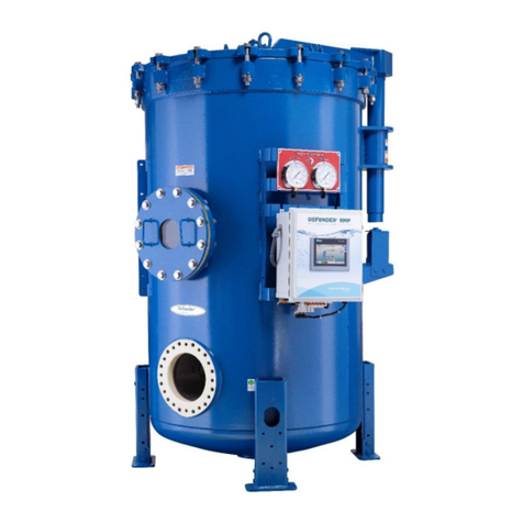
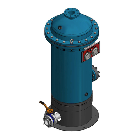
Evoqua CT Series User manual

Page 1 of 25
Evoqua Water Technologies
Industrial Products and Services
725 Wooten Rd
Colorado Springs, CO 80915
Technical Support: 800-875-7873 ext. 5000
Telephone: 978-934-9349
Fax: 978-458-6922
Operation and
Maintenance
Manual
CT Series
Stainless Steel
Carbon Tower
Filtration Systems
Model #CT-150-P (modified)
Serial #2034/000424-01 and -02
#2034/000424_OM S5000-030
Rev. 1 Date: 01 July, 2015


Page 2 of 25
CAUTIONS AND WARNINGS
Prior to operating or servicing this device, this manual must be read and understood. If
something is not clear, call for assistance before proceeding. Keep this and other associated
manuals for future reference and for new operators or qualified service personnel.
All electrical work should be performed by a qualified electrician in accordance with the latest
edition of the National Electrical Code, as well as local codes and regulations.
To avoid electrical shock hazard, do not remove covers or panels when power is supplied to
the device. Do not operate the device when covers or panels are removed.
WARNING A faulty pump motor or wiring can be a serious shock hazard if it or
surrounding water is accessible to human contact. To avoid this danger,
DO NOT remove any grounding wire from the system.
DISCLAIMER STATEMENT
This operation and maintenance manual is intended to be used with the component
manufacturer literature provided in the Appendix. These manuals should provide complete and
accurate information to meet your operating and/or service requirements based on the
information available at the time of publication. However, Evoqua Water Technologies
assumes no responsibility for the technical content of the manufacturer literature.
This manual should be read fully and understood before installation, operation or maintenance
of the system is attempted. The information in this manual may not cover all operating details
or variations or provide for all conditions in connection with installation, operation and
maintenance. Should questions arise which are not answered specifically in this manual,
contact the Evoqua Water Technologies Technical Support Department at the phone number
provided on the cover of this manual.
Evoqua Water Technologies reserves the right to make engineering refinements that may not
be reflected in these manuals. The material in these manuals is for informational purposes and
is subject to change without notice and should not be construed as a commitment by Evoqua
Water Technologies. Evoqua Water Technologies assumes no responsibility for any errors that
may appear in this document. This manual is believed to be complete and accurate at the time
of publication. In no event shall Evoqua Water Technologies be liable for incidental or
consequential damages in connection with or arising from the use of this manual.
© 2006 Evoqua Water Technologies Corp.
Printed in the United States of America. All rights reserved.
THIS BOOK OR PARTS THEREOF MAY NOT BE REPRODUCED IN ANY FORM
WITHOUT THE WRITTEN PERMISSION OF THE PUBLISHERS.

Page 3 of 25
PROPRIETARY RIGHTS STATEMENT
This manual discloses information in which Evoqua Water Technologies has proprietary
rights. Neither receipt nor possession of this manual confers or transfers any right to the client,
and by its retention hereof, the client acknowledges that it will not reproduce or cause to be
reproduced, in whole or in part, any such information except by written permission from
Evoqua Water Technologies. The client shall have the right to use and disclose to its
employees the information contained herein for the purpose of operating and maintaining the
Evoqua Water Technologies equipment, and for no other purpose. In the event the content of
this manual is altered or section/items are omitted during a reproduction, in whole or in part,
and instructions or definitions within the reproduction result in personal injury to those who
follow the altered instructions, the burden of responsibility for personal injury falls solely on
the party who affects the reproduction.
MANUAL USER’S GUIDE
This manual describes the procedures necessary to install, operate, and maintain your Evoqua
Water Technologies Simplex Filter system. Please read this manual carefully before installing
and operating your equipment. The equipment warranty may be voided if installation or
operation instructions are not followed correctly.
Warnings, Cautions, and Notes are used to attract attention to essential or critical information.
Warnings and Cautions w ill appear before the text associated with them, and notes can appear
either before or after associated text.
WARNING Warnings indicate condition, practices, or procedures which must be
observed to avoid personal injury or fatalities.
CAUTION Cautions indicate a situation that may cause damage or destruction of
equipment or may pose a long term health hazard.
NOTE: Notes are used to add information, state exceptions, and point out areas that
may be of greater interest or importance.

Page 4 of 25
EQUIPMENT SUPPORT
Evoqua Water Technologies continually strives to provide safe, efficient, trouble-free
equipment using the optimum technology for your application. If problems should develop,
our worldwide network of technical support will be available to provide assistance. For
service, sales, parts, or additional manual copies call your area representative or Evoqua Water
Technologies Technical Support Department at the number provided on the cover of this
manual.


Page 5 of 25
TABLE OF CONTENTS
SECTION DESCRIPTION PAGE
1.0 Equipment Description ....................………................……............ 6
2.0 System Introduction.........................................…............................. 7
3.0 General Description.........................................................………..... 10
4.0 Installation....................................................................………........ 11
5.0 Start-up....................................................................…...................... 13
6.0 Operation....................................................................…................... 17
7.0 Maintenance ....................................................................………..... 21
8.0 Valve Automation Section................................................……….... 23
9.0 APPENDIX – Engineering Documents.......................………......... 25
Revision History
Rev. Date Description of Revision Author
0 August 2006 Std Carbon Tower Manual S5000-030 n/a
1 01 July 2015 Revised to SST face piping valves, and revised tags to “FV-“ and “HV-“ ,
other general clarifying edits in BLUE D. Rufenacht


Page 6 of 25
EQUIPMENT DESCRIPTION CT Series Carbon Tower O&M Manual Rev. 1, 07/15
1.0 EQUIPMENT DESCRIPTION
CARBON TOWER MODEL #: __CT-150-P (modified with A-B control and SST valves)__
SERIAL NUMBERS #: ___________#2034/000424-01 and -02________________
CONTROL OPTIONS:
Manual .......................................………………….......................................................
Automatic ...................................………………...........................................................


Page 7 of 25
GENERAL DESCRIPTION CT Series Carbon Tower O&M Manual Rev. 1, 07/15
2.0 SYSTEM INTRODUCTION
This manual covers installation, operation and maintenance of the CT Series Stainless Steel
Carbon Tower with either Manual or Automatic valve actuation. Additional manuals are
required for any related equipment (e.g., softeners, and prefilters). If you do not have all the
required manuals, call Technical Support.
Although Evoqua Water Technologies strongly recommends that all users read the entire
contents of the CT Series Stainless Steel Carbon Tower manual, we also recognize that some
experienced technicians may desire a quick start summary of essential information.
Your warranty may be voided if installation or operation instructions contained in the
CT Series Stainless Steel Carbon Tower manual are not followed exactly.
At a minimum, please read these instructions before attempting to install or operate your
equipment.
Installation Precautions
Potentially dangerous electrical power is present inside the control panel (automatic option
only). THEREFORE, BEFORE TOUCHING THE INSIDE OF THE ENCLOSURE,
CONFIRM THAT AC POWER TO THE PANEL HAS FIRST BEEN DISCONNECTED
AND LOCKED OUT ACCORDING TO STANDARD LOCKOUT / TAGOUT
PROCEDURES.
To reduce the possibility of electric shock, confirm that all GROUND WIRES ARE
PROPERLY CONNECTED.
All electrical and plumbing connections should be made by trained qualified personnel and in
accordance with state and local codes.
The Carbon Tower should be lifted or moved by qualified riggers only. Safe lifting practices
should be utilized at all times.
All water used to rinse the filter media must be disposed of according to state and local codes
and must not be consumed by humans or animals.
Equipment handlers should be informed not to lift or pull any of the columns or components
by their piping assemblies.
The inlet water pressure must be within the design range of the Carbon Tower as defined in
the Specifications. If pressure is excessive, install a pressure regulator in the feed water supply
line.

Page 8 of 25
GENERAL DESCRIPTION CT Series Carbon Tower O&M Manual Rev. 1, 07/15
The Carbon Tower must be protected from water hammer. If there is excessive water hammer,
install a properly sized accumulator in the feed water supply line.
Wiring modification changes are not to be made without prior authorization from Evoqua
Water Technologies. If changes are made they must be documented and reported back to
Evoqua Water Technologies.
Installation of the Carbon Tower must be completed in accordance with the procedures
outlined in this manual. If deviations from the prescribed procedures are deemed necessary to
achieve the desired performance, consult Evoqua Water Technologies for assistance before
making any modifications.
Operating & Maintenance Precautions
Never operate the Carbon Tower with the Control Panel door open. Always use Lock-
Out/Tag-Out procedures whenever performing any type of service or maintenance on the
Carbon Tower.
Never remove any components from the Carbon Tower without first relieving pressure from
the column. This includes pressure gauges, plumbing fittings, valves and tubing connections.
Important Safety Information
OXYGEN DEPLETION CAUSED BY ACTIVATED CARBON IN CONFINED VESSELS
It has been reported in the literature* that wet activated carbon preferentially removes oxygen
from the air. When confined in large, closed vessels, the oxygen depletion can be rapid and
can reach hazardous levels. Death can be caused unless proper safety procedures are followed.
Reference was made to a fatal accident, which occurred, on a project in which a granular
activated carbon system was being installed. A carbon filtration tank was filled using water as
the fluid medium for pumping the carbon through the top of each vessel. The water was
drained off through a drain at the bottom. Two workmen were overcome after they entered the
tank to rake the bed level.
To simulate the condition, in investigating the cause of the accident, the tank was re-closed
and opened the following morning. At that time, no toxic gases were found, but the oxygen
content was only 12 %. Several other similar tanks that had been closed for several weeks
were found to have oxygen levels as low as 2 %. Other tests in laboratory sized equipment
revealed that essentially complete depletion of oxygen may occur in 33 minutes.
Recent studies have confirmed that DARCO brand activated carbons also exhibit this
phenomenon. Until more studies are completed, it would be prudent to assume that similar
effects may result with other liquid systems or with dry carbon.

Page 9 of 25
GENERAL DESCRIPTION CT Series Carbon Tower O&M Manual Rev. 1, 07/15
Appropriate safety measures should always be taken before entering and while working in any
confined space. Refer to Safety Guide SG-10 “Recommended Safe Practices and Procedures,
Entering Tanks and Other Enclosed Spaces” available from Manufacturing Chemist
Association, 1825 Connecticut Ave., N.W. Washington D.C. 20009.
* Journal of Occupational Medicine, Vol. XV, No. 10, Pg. 820 October 1973.


Page 10 of 25
GENERAL DESCRIPTION CT Series Carbon Tower O&M Manual Rev. 1, 07/15
3.0 GENERAL DESCRIPTION
The Carbon Tower removes chlorine, chloramine, and total organic compounds from the feed
water. In addition to supplying chlorine/chloramine free water for the plant production needs,
many treatment processes like reverse osmosis and demineralization often must have the
chlorine/chloramine removed from the feed water prior to exposure to the equipment. The use
of activated carbon for dechlorination provides an effective means to protect this equipment
from chlorine. Carbon also reduces the level of some organics in the feed water.
During operation, many various sized particles may become trapped within the carbon bed,
leading to an increase in pressure losses across the unit. These particles are easily removed
during backwashing, thus decreasing the pressure loss across the Carbon vessel.
The unit is pre-assembled and tested. Media is a separate purchase and shipped separately.
Mechanical Description
Pressure vessels (towers) are made of either 304 or 316L Stainless Steel and no external or
internal coatings are utilized.
All piping is Stainless Steel. All valves are either wafer style butterfly valves incorporating
corrosion resistant stainless steel (SST) body and stainless steel disc and shaft (FV-x), or are
stainless steel ball valves (HV-x). Please refer to the system drawings to see which valves are
FV’s and HV’s.
A Stainless Steel inlet manifold is supplied to disperse influent water and to collect backwash
effluent water. The bottom distributor utilizes Stainless Steel V-slot well-screen for maximum
media retention, minimal plugging and reduced pressure drop.
Access port is provided in the top head of the tower for media loading and maintenance.
Pressure gauges are included on inlet and outlet piping to verify proper operation of the
Tower. The media is activated carbon with a minimum 5’ bed depth for increased contact
time.
Operational Modes
The Carbon Tower has three modes of operation. They are Service, Backwash, and Offline.
The Service mode delivers water to equipment downstream. The Backwash mode first
removes trapped particulate, then a settle period reclassifies the bed, then a rinse period sends
loosened particulates to drain by flowing the backwash water out of the bed and assures good
treated water to service. The Offline mode is all vales closed and no water production.
The Service, Backwash and Offline modes of operation can be initiated either by manual or
automated valve orientation. If the automatic option has been selected, the backwash cycle
can be on a scheduled program or operator initiated. See the Controls Write-Up
(2034/000424_CWU.doc) for further details.


Page 11 of 25
INSTALLATION CT Series Carbon Tower O&M Manual Rev. 1, 07/15
4.0 INSTALLATION
CAUTION Equipment handlers should be informed not to lift or pull the Carbon Tower by
its piping assembly.
RECEIVING
Upon receiving the equipment, a thorough inspection should be made for damages that may
have occurred during transit. All damages should be reported to the carrier immediately.
ERECTING
The Carbon Tower should be located, erected, positioned convenient to the following:
An open type waste drain capable of handling a flow rate 20 % greater than the Backwash
flow rate (See Specifications) of the filter, normally one (1) pipe size larger than the
pipeline provided on the equipment.
A power source and air supply must be brought to the Control Panel. The electrical power
source and air source for the Control Panel are to be Customer supplied.
PLUMBING REQUIREMENTS
Install a properly sized, ASME code stamped relief valve (2” class 150 connection) on the
top of the vessel.
Install any required instrumentation. It is highly recommended to install a flow meter on
the inlet line to enable the setting of backwash, rinse, and service flow rates.
If required, install the vacuum breaker and air release valves.
The influent water supply pressure must be within the Design range (See Specifications) of
the filter.
If the pressure is excessive, install a pressure regulator in the influent pipeline.
The filter must be protected from any water hammer that may occur.
If there is excessive water hammer, install a properly sized accumulator in the influent
pipeline.
Manual isolation valves should be installed in the influent, effluent and drain lines.
If the Automatic option has been selected any loss of Plant Air to the Control Panel will
place all valves automatically in the CLOSED position.
a) Install a pipeline from the water source to be treated to the influent connection on the
filter column. Size the pipe to handle the maximum Service or Backwash water flow
rate of the filter.
b) Install a pipeline from the Drain connection on the Carbon Tower to an open type
waste drain.
c) Install a pipeline from the effluent connection on the Carbon Tower to the Service
points of use.
d) Install a pipeline from the Plant Clean Air supply to the air inlet connection on the
Control Panel. Install a manual isolation and check valve in this pipeline.

Page 12 of 25
INSTALLATION CT Series Carbon Tower O&M Manual Rev. 1, 07/15
e) Install a pipeline from the house Steam supply line to either of the steam ports
depending on the whether the client's preference is to steam from the top or bottom of
the tower.
f) Install a condensate line to the Steam Condensate Out connection on the Carbon
Tower.
NOTE: If you wish to steam from the bottom you must purchase and install a steam
trap on the condensate outlet connection.
ELECTRICAL REQUIREMENTS
Electrical service is only required if the Automatic option was selected
a) 120VAC/ 1Ph/ 60HZ Control Power to Panel (Entry Needed on Right Side of
Enclosure)
NOTE: All system flow control and monitoring is presumed to be outside of Evoqua Water
Technologies CT equipment boundaries. However, for your convenience, limit stop
adjustments have been included on the Process Outlet, Rinse Outlet, and Backwash
Outlet valves. The procedure for the adjustment of these stops can be found in the
Manufacturer’s Literature.

Page 13 of 25
START-UP CT Series Carbon Tower O&M Manual Rev. 1, 07/15
5.0 START-UP
NOTE: The Carbon Tower is pressure tested at the factory, but during shipping connections
may loosen. Once the Carbon Tower is installed in your facility, it is recommended
that the Tower be pressure tested again following the procedure described below.
NOTE: All system flow control and monitoring is presumed to be outside of the equipment
boundaries. However, for your convenience, limit stop adjustments have been
included on the Process Outlet, Rinse Outlet, and Backwash Outlet valves. The
procedure for the adjustment of these stops can be found in the Manufacturer’s
Literature.
FOREWORD
Prior to placing the Carbon Tower in service it must be pressure tested and checked for leaks.
The internals must also be checked and the carbon media must be loaded and flushed.
FILL & PRESSURE TEST
WARNING Do not exceed design pressure. Failure to follow this warning can result in serious
injury to personnel and damage to the equipment.
a) Confirm that all manual valves on the Carbon Tower are in the closed position. (If the
automatic option has been chosen with the control panel in the “Off” position and the
compressed air source “off” all automatic valves will be in the closed position)
b) Open “HV-6” [steam outlet] and this will allow the tank to vent as it fills with water.
c) Turn “on” the clean free dry air and set the pressure regulator to 80 psig.
d) Open “FV-3” then open “FV-1”, this will allow the inlet feed water to fill the tower. (If the
automatic option has been chosen, you will need to disconnect the instrument tubing from
“FV-4” & “ FV-5” and use a cap on the end of the tubes, this will eliminate these valves
being actuated.
e) Once water flows out of the vent valve “HV-6” close this valve and the entire system will
pressurize to whatever the feed pressure is.
f) At the conclusion of the pressure test return all valves to the closed position. (If the
automatic option has been chosen you will need to turn the control panel and the
compressed air “off” to perform the “DRAIN TOWER” procedure (next section) then
reconnect the air supply lines to “FV-4” & “ FV-5”.
WARNING Do not exceed design pressure. Failure to follow this caution can result in
serious injury to personnel and damage to the equipment.
If leaks occur, relieve pressure, drain column, if necessary, make repairs, then refill and re-
pressure test. After the Carbon Tower has been checked for leaks, drain the tower in
preparation for loading media.

Page 14 of 25
START-UP CT Series Carbon Tower O&M Manual Rev. 1, 07/15
BACKWASH AND RINSE VALVE SETTINGS
It is necessary to set the backwash outlet and rinse outlet flow rates via the travel stops located
on the valves (FV-2 and FV-4, respectively). It is highly recommended that these valves are
adjusted under flowing conditions and prior to media being installed in the tank. This will
minimize the risk of dumping excessive media to drain.
a) Please note the default times for each wash step, the set the times on the HMI for a
minute or two for each of these steps (backwash, settle, and rinse). This should be
sufficient to set the flows.
b) Place the Carbon Tower in wash mode.
c) Adjust FV-2 during the backwash cycle to the appropriate flow as listed in the
specifications.
d) Adjust FV-4 during the rinse cycle to the appropriate flow as listed in the
specifications.
DRAIN TOWER
a) Confirm that all manual valves on the Carbon Tower are in the closed position. (If the
automatic option has been chosen with the control panel in the “Off” position and the
compressed air source “off” all automatic valves will be in the closed position)
b) Open the vent valve “HV-6”
c) Open the drain valve “HV-7”
INSPECT COLUMN INTERNALS
a) Remove the top manway of the tower, inspect column internals for any shipping damage
and make repairs if required.
b) After inspecting column internals, proceed to load media.
LOADING MEDIA
CAUTION Be careful not to damage the internal distributors of the Carbon Tower. Do not
allow any foreign objects to fall into the column while loading media. Presence of
foreign objects can cause damage.
There are two ways that media can be loaded, either manually through the “Man-way” or
using the “Media Sluice Inlet” and “Media Sluice Outlet” connections on the vessel.
Manual Media Loading
This requires several individuals and is accomplished by lifting the bags of carbon
(supersacks) up to the Man-way at the top of the tower and pouring the carbon into the tower.
Please note that it is critical to have the tower full of water enough to be 1-foot over the lateral
system so that the internals are not damaged during the media loading process.
This manual suits for next models
1
Table of contents
Other Evoqua Water Filtration System manuals
Popular Water Filtration System manuals by other brands

Del ozone
Del ozone aquaclipse ZO-400 Owner's manual and usage guide
Klarstein
Klarstein PURELINE manual

Camfil
Camfil FB Series Installation, operation and maintenance manual
HydroCare
HydroCare DUALPLEXX Installation, use & care manual
emaux
emaux CLL Series manual
Topper
Topper WOW RO 50 Installation & user manual

Ultimaker
Ultimaker S5 Air Manager quick start guide
ACO
ACO Lipumax-P installation guide

Blagdon
Blagdon MIDIPOND 10000 Guide

Blanco
Blanco BLANCO EVOL-S Pro Filter user manual

Zen Water
Zen Water 4G-MP Assembly & maintenance guide
Drinking Fountain Doctor
Drinking Fountain Doctor EHOA8 1G Installation use and care manual

