Schaudt SDTBUS 630 User manual
Date:14.12.2018
ESchaudt GmbH, Elektrotechnik und Apparatebau, Planckstraße 8, 88677 Markdorf, Germany, Tel. +49 7544 9577-0, Fax +49 7544 9577-29, www.schaudt--gmbh.de
8110605 BA / EN
Instruction Manual
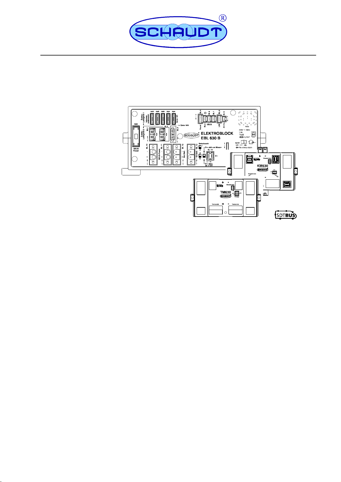
SDTBUS 630 with
Electroblock EBL 630 B
Bus modules XM 630 B/631 B/632 B
Table of contents
1 Safety information 2......................................
1.1 Meaning of safety symbols 2...............................
1.2 General safety information 2...............................
2 Purpose 3...............................................
3 Layout 5................................................
3.1 Electroblock EBL 630 B 5..................................
3.2 Bus modules in the 630 family 6............................
4 Operation 9..............................................
4.1 Switching on and off the 12V supply for the leisure area 9......
4.2 Shutting down 10..........................................
4.3 Changing the battery 11....................................
5 Battery charge functions 12.................................
6 Faults 12.................................................
7 Technical details 14........................................
7.1 EBL 630 B 14.............................................
7.2 Bus modules 14...........................................
7.3 Charging curve 15.........................................
8 Maintenance 15...........................................
Operating instructions Bus System SDTBUS 630 mit EBL 630 B
2Date:14.12.2018 8110605 BA / EN
1 Safety information
1.1 Meaning of safety symbols
DANGER!
Failure to comply with this sign may result in danger to life or physical condition.
WARNING!
Failure to comply with this sign may result in injury.
ATTENTION!
Failure to comply with the sign may result in damage to equipment or other connected
loads.
1.2 General safety instructions
The design of the device is state-of-the-art and complies with approved safety regula-
tions. Failure to observe the safety instructions may nonetheless lead to injury or damage
to the device.
Only use the device when it is in perfect technical condition.
Any faults affecting the safety of individuals or the proper functioning of the device must
be repaired immediately by specialists.
DANGER!
The device contains live parts carrying 230V. These present a danger of death due to
electric shock or fire so So therefore:
FDo not carry out maintenance or repair work on the device
FIf cables or the device housing are damaged, no longer use the device and isolate
it from the power supply
FEnsure that no liquids enter the device
WARNING!
Hot components can cause burns. So therefore:
FOnly change blown fuses when the device is fully de-energised
FBlown fuses may only be replaced once the cause of the fault is known and has
been rectified
FNever bypass or repair fuses
FOnly use original fuses rated as specified on the device
FDevice parts can become hot during operation. Do not touch them.
FNever store heat sensitive objects close to the device (e.g. temperature sensitive
clothes if the device has been installed in a wardrobe)
ATTENTION!
The electroblock, 12V consumers and connected devices can be damaged if the thres-
holds for the 230V supply are exceeded. So therefore:
FEnsure that a generator complies with the mains connected load values.
FDo not connect the generator until it is running smoothly
FDo not connect the electroblock to the mains supply on board passenger vehicle
ferries (a correct mains supply is not always guaranteed on board these ferries)
Generator
operation
and
passenger
vehicle
ferries
Operating instructions Bus System SDTBUS 630 mit EBL 630 B
3
Date:14.12.2018
8110605 BA / EN
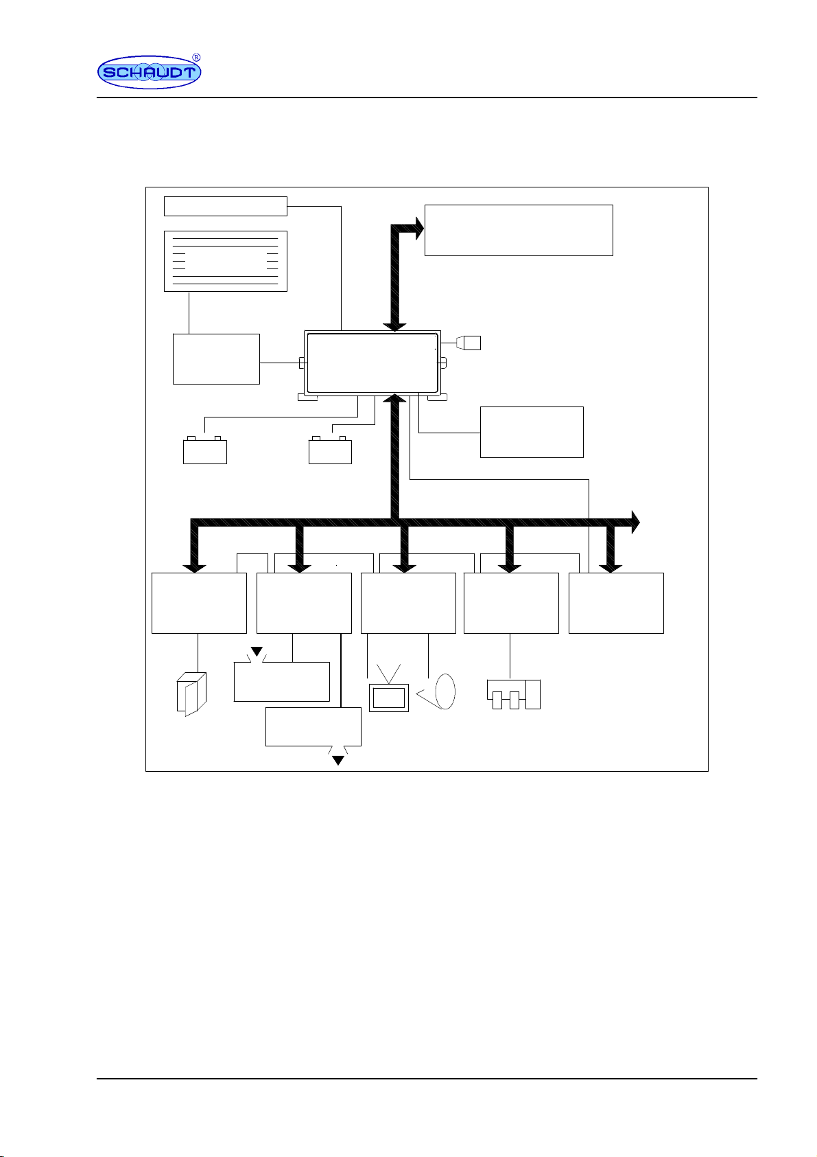
2 Purpose
The EBL 630 B electroblock, together with the bus modules in the 630 family, is the cen-
tral power supply unit for all 12V consumers in the vehicle’s electrical system.
+-- +--
230V ~
Water tank
Waste water
tank
Auxiliary
charger
LAS ...
(accessory)
Electroblock
EBL 630 B
Solar
regulator
LR...
(accessory)
Solar module
(accessory)
Starter battery Leisure battery
12V consumers / tanks / etc...
Outside temp.
Refrigerator
module
KM 630
Tank
module
TM 630
Output
module 1
AM 631
Pumps
module
PM 630
...
Other
modules
(optional)
Main 12V supply
...
Other
modules
(optional)
SDTBUS630
Bus-compatible
LT ... / DT ...
operator and control panel
SDTBUS630
Fig. 1 On-board power supply system
The EBL 630 B electroblock comprises:
Fa charge module for charging all batteries connected
Foutput ”main 12V supply” for the bus modules
Fconnections for the batteries
Fan internal bus module for the SDTBUS 630 to be able to transfer readings to the
bus
The individual bus modules are used for the complete 12V distribution system and for
fusing the 12V circuits.
Modules
Operating instructions Bus System SDTBUS 630 mit EBL 630 B
4Date:14.12.2018 8110605 BA / EN
A bus-compatible IT ... or DT ... control and display panel must be connected to the EBL
630 B for operation. Bus modules are also required. Together these devices control the
electrical functions in the vehicle’s leisure area, including accessories.
It is also possible to connect up to 2 auxiliary chargers and a solar regulator to the EBL
630 B.
Flat vehicle fuses protect the various input circuits of the chargers. All outputs on the bus
modules are fused with polyswitch fuses.
The entire system is protected against:
FExcess temperature
FOverload
FShort circuit
ATTENTION!
Connecting the battery with inverse polarity poses of risk of damaging the electroblock.
System
devices
Protective
circuits

Operating instructions Bus System SDTBUS 630 mit EBL 630 B
5
Date:14.12.2018
8110605 BA / EN
3 Layout
3.1 Electroblock EBL 630 B
12345678
11
9
19 2018171514131210 16
Fig. 2 Layout of the EBL 630 B electroblock (front)
1 Installation feet
2 D+ connector (input/output)
3 D+ signal changeover switch
4 Battery type switch (A/B, 1/2)
5 Block 13: Starter battery
6 Block 12: Leisure battery
7 Block 11: 12V main supply, bus modules
8 Block 10: 12V main supply, bus modules
9 Main fuse, main 12V supply
10 Block 1: Auxiliary charger 1
11 Flat vehicle fuses
12 Block 2: Auxiliary charger 2
13 Block 3: Solar regulator
14 Block 4: Operator and control panel
15 Diagnostics LED
16 Blocks 5, 6, 7: SDTBUS 630
17 Block 8: LIN bus
18 Block 9: Outside temperature sensor
19 Mains connector (optional low power de-
vice socket, otherwise mains cable with
WAGO connector)
20 Housing
12
Fig. 3 Layout of the EBL 630 B electroblock (rear)
1 Cover plate 2 Nameplate
Operating instructions Bus System SDTBUS 630 mit EBL 630 B
6Date:14.12.2018 8110605 BA / EN
3.2 Bus modules in the 630 B family
All bus modules are designed for a 12V power supply. If nothing else is specified, the ma-
ximum output currents of the individual outputs on the modules is 90% of the value of
relevant polyswitch fuse.
The following bus modules can be used in the SDTBUS 630 bus system (see also
Fig. 1):
Name Purpose Comment
KM 630 B Refrigerator
TM 630 B Tank sensors
PM 630 B Water pump
HM 630 B Heater
AM 631 B Outputs Up to four module may be connected
AM 632 B Outputs Up to four module may be connected
Please refer to the manufacturer’s vehicle documents for the bus modules actually avai-
lable in the vehicle.
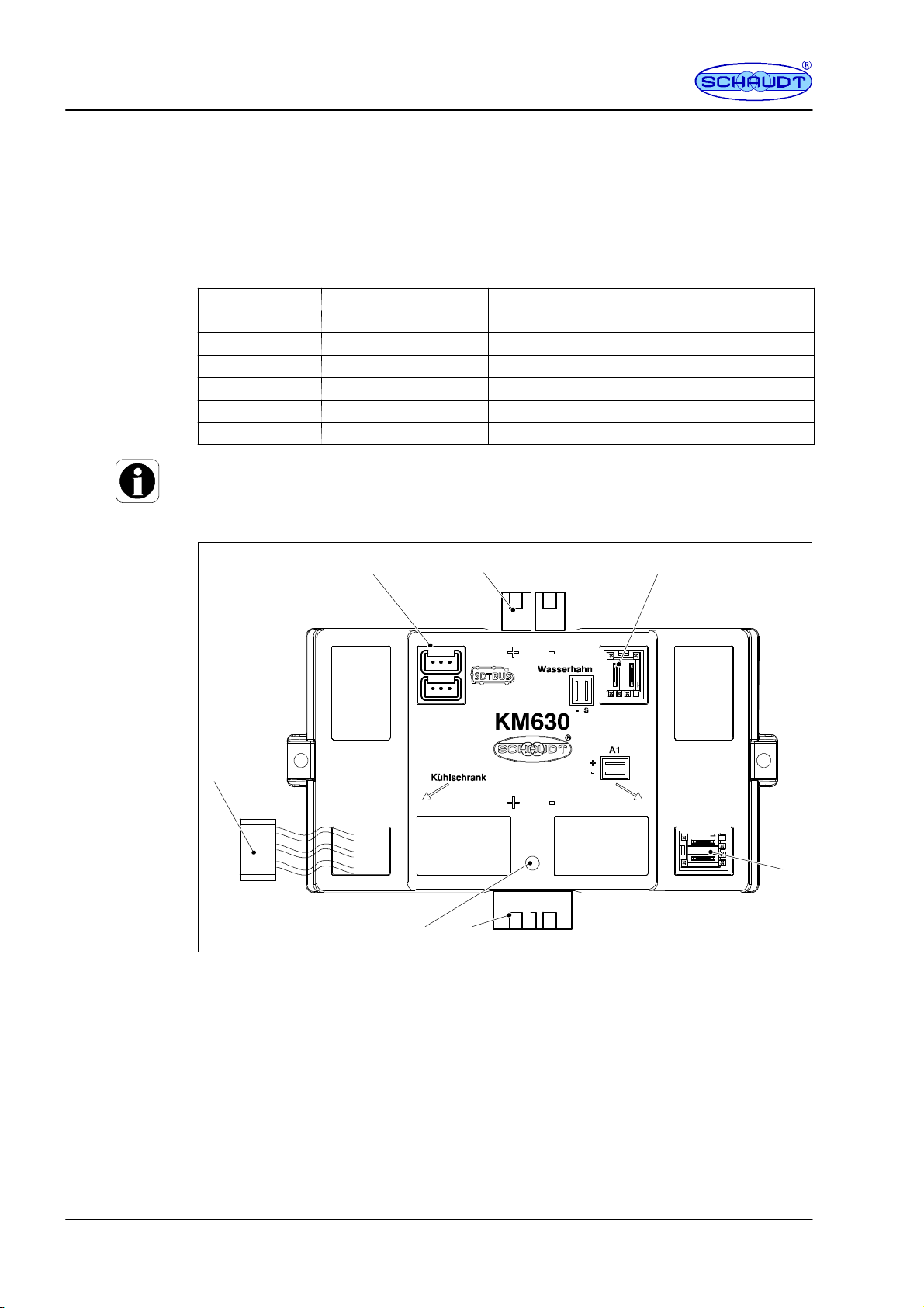
3.2.1 Fridge module KM 630 B
2
645
3
7
1
Fig. 4 Layout of the KM 630 B fridge module
1 Diagnostics LED
2 Main 12V supply (input)
3 Switched output A1
4 Water tap connection
5 Main 12V supply (output)
6SDTBUS 630 connection
7 Refrigerator connector

Operating instructions Bus System SDTBUS 630 mit EBL 630 B
7
Date:14.12.2018
8110605 BA / EN
3.2.2 Tank module TM 630 B
3
867
5
1 42
Fig. 5 Layout of TM 630 B tank module
1 Tank probe 1
2 Diagnostics LED
3 Main 12V supply (input)
4 Tank probe 2
5 Water pump output
6 Water tap connection
7 Main 12V supply (output)
8SDTBUS 630 connection
3.2.3 Water pump module PM 630 B
2
645
3
1
7
Fig. 6 Layout of the PM 630 B pump module
1 Diagnostics LED
2 Main 12V supply (input)
3 Connectors for water taps 1 and 2
4 Connector for WC pump switch and WC valve
5 Main 12V supply (output)
6SDTBUS 630 connection
7 Water pump connector

Operating instructions Bus System SDTBUS 630 mit EBL 630 B
8Date:14.12.2018 8110605 BA / EN
3.2.4 Heater module HM 630 B
3
645
2
1
7
Fig. 7 Layout of the HM 630 B heater module
1 Not used (nc)
2 Diagnostics LED
3 Main 12V supply (input)
4 Heater supply
5 Main 12V supply (output)
6SDTBUS 630 connection
7 EisEx connector
3.2.5 Output module AM 631 B
3
857
2
1
9
4
6
Fig. 8 Layout of AM 631 B output module
1 Selector switch, function of outputs A1
2 Diagnostics LED
3 Main 12V supply (input)
4 Selector switch, function of outputs A2
5 Outputs A2.1 and A2.2 (connected in parallel)
6 Address coding switch
7 Main 12V supply (output)
8SDTBUS 630 connection
9 Outputs A1.1 and A1.2 (connected in parallel)
Operating instructions Bus System SDTBUS 630 mit EBL 630 B
9
Date:14.12.2018
8110605 BA / EN
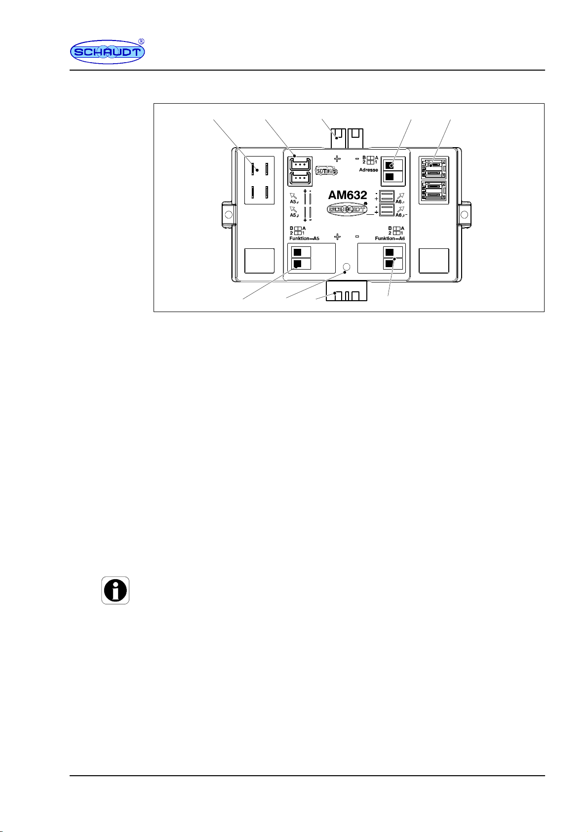
3.2.6 Output module AM 632 B
3
857
2
1
9
4
6
Fig. 9 Layout of AM 632 B output module
1 Selector switch, function of outputs A1
2 Diagnostics LED
3 Main 12V supply (input)
4 Selector switch, function of outputs A2
5 Outputs A6.1 and A6.2 (connected in parallel)
6 Address coding switch
7 Main 12V supply (output)
8SDTBUS 630 connection
9 Outputs A5.1 and A5.2 (connected in parallel)
4 Operation
No action is required on the EBL 630 B electroblock or any of the bus modules for daily
operation. The system is operated solely via the IT ... / LT ... control and switch panel
connected. .
One-off configuration is only required after the type of battery (lead-acid or lead-gel) has
been changed, during commissioning or when upgrading with accessories (see section
4.3 and the installation instructions for the SDTBUS 630 bus system for details).
4.1 Switching on and off the 12V supply for the leisure area
The 12V supply for the leisure area is switched on and off from the IT ... / LT ... connec-
ted.
Following the instructions for the operator and control panel.
The outputs of bus modules AM 631 B and AM 632 B are exceptions -- they are configu-
red such that they are not affected by ”12V ON” (see installation instructions). These
could be for example:
FSteady plus
FHeater
FAES/compressor refrigerator
FAuxiliary heater
FStep
FAwning light
12V is normally applied to these outputs. They can then only be switched off with a shut-
down (see Section 4.2).
Operating instructions Bus System SDTBUS 630 mit EBL 630 B
10 Date:14.12.2018 8110605 BA / EN
4.2 Closing down
The system should be shut down if the motorhome is not being used for a lengthy period
(such as during the winter).
A shutdown completely isolates the leisure battery from all consumers in the leisure area
-- also from those normally powered continuously. The IT ... / LT ... operator and control
panel is an exception .
ATTENTION!
The leisure battery may be damaged beyond repair if totally discharged. So therefore:
FFully charge the leisure battery before and after a shutdown (connect the vehicle to
the mains for at least 12 hours and 24 hours for an 80Ah and 160Ah battery re-
spectively)
The shutdown is performed by the IT ... / LT ... operator and control panel connected.
Following the instructions for the operator and control panel.
4.3 Changing the battery
ATTENTION!
Using incorrect battery types or incorrectly rated batteries can result in damage to the
battery or devices connected to the electroblock. So therefore:
FBatteries may only be changed by qualified personnel.
FFollow the battery manufacturer’s instructions.
FOnly connect the electroblock to 12V power supplies with rechargeable 6 cell lead-
gel, lead-acid or AGM batteries. Do not use any unsuitable battery types.
Normally only batteries of the same type and rating should be used, i.e. the same as
those originally installed by the manufacturer.
It is possible to swap lead-acid batteries with lead-gel batteries. However, swapping from
lead-gel batteries to lead-acid batteries is only possible in certain circumstances. Contact
the vehicle manufacturer for more information.
Suitability must be checked using information from the battery supplier and the charging
parameters of Schaudt equipment. The charging parameters of the EBL 630 B electro-
block are specified in the operating and installation instructions.
DANGER!
Incorrectly setting the battery selector switch can cause a risk of explosion from a build-
up of detonating gas (e.g. when a battery is defective, a battery charger is defective or for
an excessively high battery operating temperature (above 30C)). So:
FMove the battery selector switch to the correct position.
Battery-
selection
Operating instructions Bus System SDTBUS 630 mit EBL 630 B
11
Date:14.12.2018
8110605 BA / EN
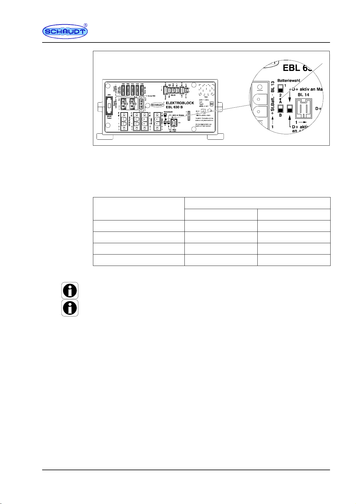
1
Fig. 10 Battery selector switch
Isolate the electroblock from the mains
Replace the battery.
Move the battery selector switch (see Fig. 10) to the correct position using a thin ob-
ject, such as a ball point pen:
B
a
t
t
e
r
y
t
y
p
e
s
e
t
*
Switch positions
B
attery type set
*
Switch 1/2 Switch A/B
Supply mode 1 A
AGM2 1 B
Lead-gel / AGM1 2 A
Lead-acid 2 B
* See also the table in Section 7.3 ”Technical details -- Charging curve”.
In supply mode, the charge regulator supplies a constant output voltage
The two switches are recessed in the front panel to rule out incorrect operation. A small
screwdriver may have to be used to switch setting.
Then re-check that the battery selector switch is in the correct position for the type of
battery used.
5Battery charge functions
Simultaneous charging of the starter battery and the leisure battery by the alternator, pa-
rallel connection of the batteries via a cut-off relay.
This mechanism provides charging of the leisure battery and automatic conservation
charging of the starter battery when the 230V mains voltage is connected to the electro-
block.
The switching option provided by the battery selector switch ensures optimum charging of
the lead-gel and lead-acid, and AGM, battery types.
If a solar regulator is connected to input block 3 (optional), a rating of up to 18A is used
for charging the two batteries.
Battery-
Selector
switch
Charging
whilst on the
move
Mains
charging
Charging
with solar
modules
Operating instructions Bus System SDTBUS 630 mit EBL 630 B
12 Date:14.12.2018 8110605 BA / EN
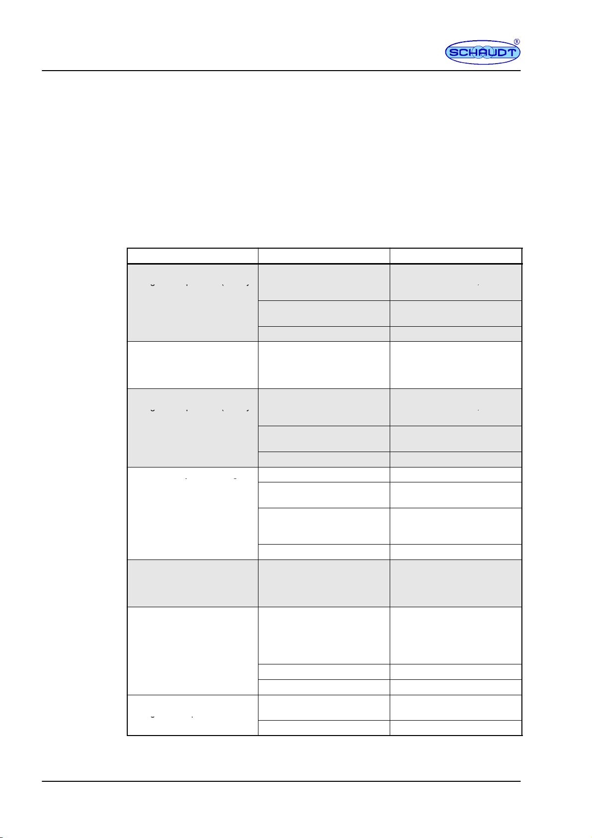
6Faults
A flat battery or defective fuse is the cause of most faults in the 12V system.
When it is not possible to rectify a fault based on the following table, please contact
Schaudt customer service (for address, see Page 17).
The following functions are protected by a polyswitch fuse:
FAll outputs of the bus modules
FControl panel / internal controller in the EBL 630 B
If a fault occurs here, the electroblock must be switched off for approx. 2 minutes and be
disconnected from the 230V mains. The polyswitch fuses of the EBL and bus modules
reset by themselves during this time.
Fault Possible cause Remedy
L
eisure batter
y
is not char
g
ed No mains volta
g
eSwitch on the automatic circuit
L
e
i
s
u
r
e
b
a
t
t
e
r
y
i
s
n
o
t
c
h
a
r
g
e
d
during 230V operation (battery
N
o
m
a
i
n
s
v
o
l
t
a
g
e
S
w
i
t
c
h
o
n
t
h
e
a
u
t
o
m
a
t
i
c
c
i
r
c
u
i
t
breaker in the vehicle; check
g
p
(
y
voltage permanently below
1
3
3
V
)
;
the mains voltage
13.3 V) Too many consumers are swit-
ched on
Switch off any consumers not
required
Defective electroblock Contact customer service
Leisure battery is overcharged
during 230V operation (battery
voltage constantly above 14.5
V)
Defective electroblock Contact customer service
Starter batter
y
is not char
g
ed No mains volta
g
eSwitch on the automatic circuit
S
t
a
r
t
e
r
b
a
t
t
e
r
y
i
s
n
o
t
c
h
a
r
g
e
d
during 230V operation (battery
N
o
m
a
i
n
s
v
o
l
t
a
g
e
S
w
i
t
c
h
o
n
t
h
e
a
u
t
o
m
a
t
i
c
c
i
r
c
u
i
t
breaker in the vehicle; check
g
p
(
y
voltage permanently below
1
3
0
V
)
;
the mains voltage
13.0 V) Too many consumers are swit-
ched on
Switch off any consumers not
required
Defective electroblock Contact customer service
Leisure battery is not charged
d
i
b
i
l
t
i
(
b
t
Defective alternator Have the alternator checked
y
g
during mobile operation (bat-
tery voltage below 13.0 V) No voltage on D+ input Have the fuse and cabling
checked
D+ switch on electroblock is
not set correctly.
Set the switch according to the
D+ signal from the vehicle (12V
or active ground)
Defective electroblock Contact customer service
The leisure battery is overchar-
ged during mobile operation
(battery voltage permanently
above 14.3 V)
Defective alternator Have the alternator checked
The refrigerator does not work
during mobile operation
No power feed to the refrigera-
tor:
-- polyswitch of KM 630 B bus
module has tripped
-- check the cabling and
switch off system for at
least 2 minutes
-- cabling interrupted -- have the cabling checked
-- No D+ signal -- have the cabling checked
The refrigerator does not work
during mobile operation
KM 630 B bus module defec-
tive
Contact customer service
g
p
Defective refrigerator Have the refrigerator checked
Flat vehicle
fuses
Polyswitch
fuses
Operating instructions Bus System SDTBUS 630 mit EBL 630 B
13
Date:14.12.2018
8110605 BA / EN
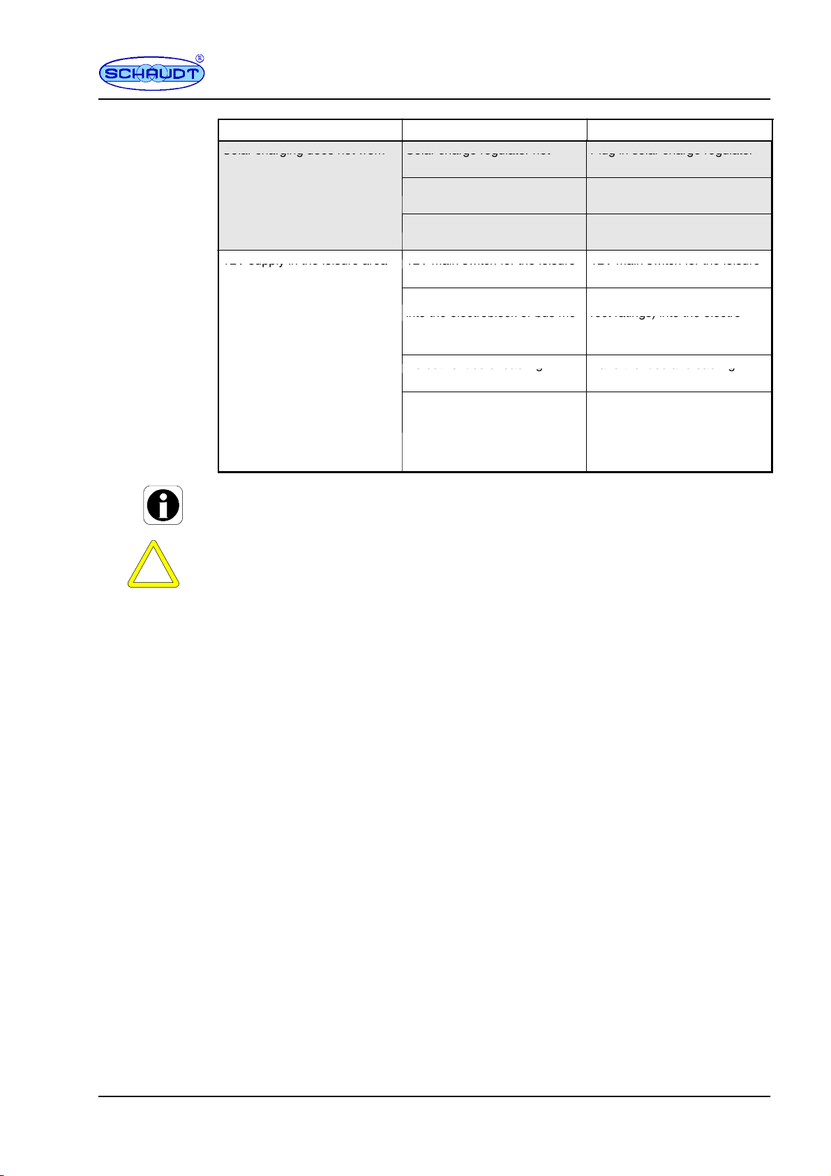
Fault RemedyPossible cause
Solar charging does not work Solar charge regulator not Plug in solar charge regulator
S
o
l
a
r
c
h
a
r
g
i
n
g
d
o
e
s
n
o
t
w
o
r
k
S
o
l
a
r
c
h
a
r
g
e
r
e
g
u
l
a
t
o
r
n
o
t
plugged in
P
l
u
g
i
n
s
o
l
a
r
c
h
a
r
g
e
r
e
g
u
l
a
t
o
r
Defective fuse or cabling Have the fuse and cabling
checked
Solar charge regulator defec-
tive
Have solar charge regulator
checked
12V supply in the leisure area 12V main switch for the leisure 12V main switch for the leisure
1
2
V
s
u
p
p
l
y
i
n
t
h
e
l
e
i
s
u
r
e
a
r
e
a
does not work
1
2
V
m
a
i
n
s
w
i
t
c
h
f
o
r
t
h
e
l
e
i
s
u
r
e
battery is switched off
1
2
V
m
a
i
n
s
w
i
t
c
h
f
o
r
t
h
e
l
e
i
s
u
r
e
battery must be switched on
Not all plugs/fuses are plugged
into the electroblock or bus mo-
Insert all plugs and fuses (cor-
rect ratings) into the electro-
i
n
t
o
t
h
e
e
l
e
c
t
r
o
b
l
o
c
k
o
r
b
u
s
m
o
dules
r
e
c
t
r
a
t
i
n
g
s
)
i
n
t
o
t
h
e
e
l
e
c
t
r
o
block -- check the connectors
on the bus modules
Defective fuse or cabling Have the fuse and cabling
D
e
f
e
c
t
i
v
e
f
u
s
e
o
r
c
a
b
l
i
n
g
H
a
v
e
t
h
e
f
u
s
e
a
n
d
c
a
b
l
i
n
g
checked
Electroblock or individual bus
modules defective
Read off error codes from the
IT ... / LT ... operator and con-
trol panel
Contact customer service if re-
quired
The charging current is reduced automatically if the device becomes too hot due to ex-
cessive ambient temperature or lack of ventilation. Always prevent the device from over-
heating nevertheless.
ATTENTION!
When the automatic shut-off of the battery monitor is activated (also see the operating
instructions for the DT / LT ... operator and control panel) , fully charge the leisure bat-
tery.

Operating instructions Bus System SDTBUS 630 mit EBL 630 B
14 Date:14.12.2018 8110605 BA / EN
7 Technical details
7.1 EBL 630 B
Weight Approx. 2 kg
Casing PA (polyamide)
Colour Gentian blue RAL 5010
Front Aluminium, powder coated, light grey (RAL
7035)
Mains connection 230V ~,10%, 47 to 63 Hz sinusoidal
Max. power consumption 230V ~1.9 A
Output voltage 12V DC
Max. overall output current, 12V DC 18 A
Storage temperature -- 20C ... 70C
Operating temperature -- 20C ... 45C
Protection class I
Protection rating IP20
Battery types Lead-acid
Lead-gel
AGM
Battery rating 55 Ah or greater
Charging for mains connection
FLeisure battery
Charging curve
Final charge voltage
Charging current
Voltage for conservation charging
IUoU
SeeFigure11
18 A in the entire mains voltage range,
electronically limited, minus the charging
current into the vehicle battery
See Figure 11, with automatic
switchover
FStarter battery
Charging current Max. 4 A
Loading of D+ connector by EBL Approx. 1 mA
Solar regulator connector MNL 3-pin, for starter battery and leisure
battery; e.g. Schaudt LR 1218
Solar regulator charge current Max. 18 A (with 20 A fusing)
Additional charger connector Minifit 2-pin, e.g. Schaudt LAS 1218
Max. permissible charge current of auxi-
liary charger
27A(fusedwith30A)
7.2 Bus modules
Please refer to the installation instructions for the technical details of the bus modules
Operating instructions Bus System SDTBUS 630 mit EBL 630 B
15
Date:14.12.2018
8110605 BA / EN
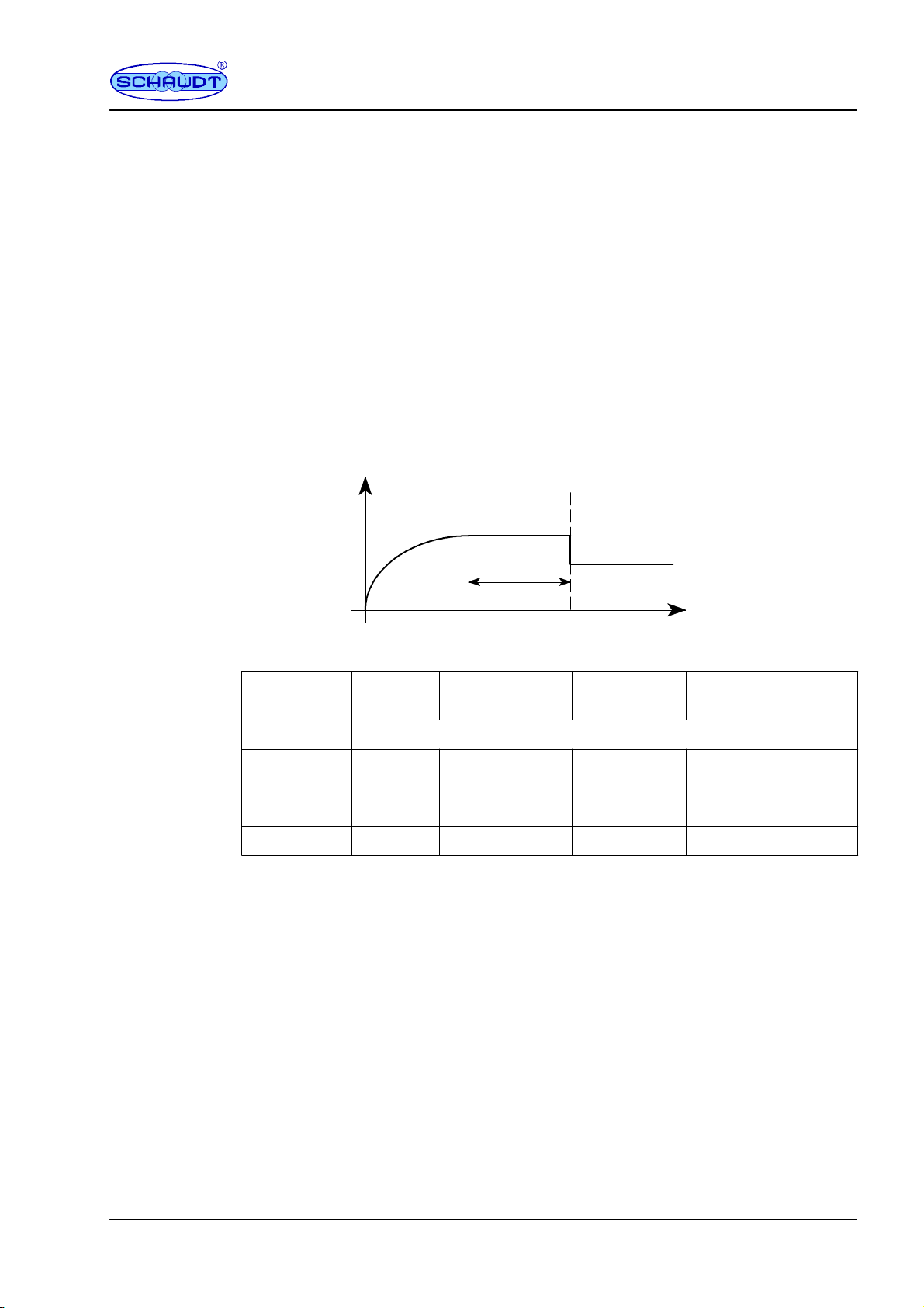
7.3 Charging curve
Charging curve IUoU
End-of-charge voltage* Between 14.45V and 14.75V @ 22.5C battery tempera-
ture (and without temperature sensor)
Charge current 18 A in the entire mains voltage range,
electronically limited, minus the
charge current into the vehicle battery
Voltage trickle charging* Between 13.55V and 13.70V @ 22.5C battery tempera-
ture (and without temperature sensor), with automatic
switchover
New charging cycle, As soon as the charging current is limited,
switchover to main charging switchover to main charging
with delay
* Dependent on the battery type set
Main charge
I
Full charge
Uo
Trickle charge
U
See table
Time
Charge voltage
Trickle charge voltage
Ucharge
V
Fig. 11 Example of the charge voltage behaviour with the LAS 1218 BUS battery charger
Battery type
set
Charge-
voltage
Trickle charge
voltage
At reference
temperature
Time phase
Supply mode Fixed voltage 12.65 V
AGM2 14.75 V 13.70 V 22,5C4 hours
Lead-gel /
AGM1
14.45 V 13.70 V 22,5C12 hours
Lead-acid 14.45 V 13.55 V 22,5C4 hours
The temperature correction of the end-of-charge voltages is --20 mV per degrees of tem-
perature increase (in relation to 25C) or +20 mV per degrees of temperature decrease
(compensation range 0 to 45CU
max 14.9V; the upper voltage limit at 14.9V is in consi-
deration of the maximum input voltage of consumers connected).
IMain charge with maximum 18 A charging current, electronically limited, up to end-of-
charge voltage. Start of charge also for completely discharged batteries.
Automatic switchover to full charge with constant charge voltage (see table above). The
duration of the full charge phase is based on the battery type and is set on the device.
Automatic switchover to trickle charging with constant voltage. In the trickle charge
phase, a constant voltage is applied to the charger module output. The battery is now
fully, or virtually fully, charged.
I
Uo
U

Operating instructions Bus System SDTBUS 630 mit EBL 630 B
16 Date:14.12.2018 8110605 BA / EN
8 Maintenance
The devices of the SDTBUS 630 bus system require no maintenance.
Clean the electroblock with a soft, slightly damp cloth and mild detergent. Never use spi-
rit, thinners or similar substances. Do not allow liquids to enter the electroblock.
No part of this manual may be reproduced, translated or copied without express written
permission.
Cleaning
E

Operating instructions Bus System SDTBUS 630 mit EBL 630 B
17
Date:14.12.2018
8110605 BA / EN
Appendix
A Customer service
Schaudt GmbH, Elektrotechnik & Apparatebau
Planckstraße 8
88677 Markdorf, Germany
Phone: +49 7544 9577-16 Email: kundendienst@schaudt-gmbh.de
Office hours Mon to Thurs 08.00 -- 12.00, 13.00 -- 16.00
Fri 08.00 -- 12.00
Before returning a device, we recommend taking a look at the frequently asked questions
(FAQs) on website ”www.schaudt-gmbh.de”. This may give you some pointers towards
fault rectification, or perhaps even also incorrect operation.
Returning a faulty device:
If possible: Fill in the pre-registration in the relevant area on the ”www.schaudt-
gmbh.de” website.
Complete and enclose the fault report, see Appendix B.
Send it to the addressee (free delivery).
B Fault report
In the event of damage, please fill in the fault report and send it with the faulty device to
the manufacturer.
Device type: _______________________
Item no.: _______________________
Vehicle: Manufacturer: _______________________
Model: _______________________
Own installation? Yes -No -
Upgrade? Yes -No -
Upstream overvoltage protection? Yes -No -
Following fault has occurred (please tick):
-Electrical consumers do not work -- which?
(please specify below)
-Switching on and off not possible
-Persistent fault
-Intermittent fault/loose contact
Other comments:
Customer
service
Send in
device

Operating instructions Bus System SDTBUS 630 mit EBL 630 B
18 Date:14.12.2018 8110605 BA / EN
C Block diagram of EBL 630 B
Minifit 2--pin BL2
Mini
f
it 2--pin B
L
1
Phönix BL12
Phönix BL13
Phönix BL10
Phönix BL11
Lumberg 3-pin BL5
Lumberg 3-pin BL7
Lumberg 5-pin BL4
Lumberg 2-pin BL9
6.3mmRAST5BL14
Lumberg 4-pin BL8
active high/active low
Lumberg 3-pin BL6
WAGO connector
230 V mains, 50Hz
Low power device socket
Auxiliary charger 1
Auxiliary charger 2
Leisure batter
y
Starter battery
Outside temperature
sensor
Optional:
MNLSocket3F--BL7

Operating instructions Bus System SDTBUS 630 mit EBL 630 B
19
Date:14.12.2018
8110605 BA / EN
D Item number compatibility list
to software version V1.01:
Device LT 6.. EBL 630 AM 631 AM 632 KM 630 TM 630 PM 630 HM 630
Item
no.
931.378
931.375
931.379
911.603 925.001 925.002 925.003 925.004 925.005 925.006
from software version V1.02:
Device LT 6.. A EBL 630 A AM 631 A AM 632 A KM 630 A TM 630 A PM 630 A HM 630 A
Item
no.
931.380
931.381
931.382
911.604 925.007 925.008 925.009 925.010 925.011 925.012
from software version V3.00:
Device LT 6.. B EBL 630 B AM 631 B AM 632 B KM 630 B TM 630 B PM 630 B HM 630 B
Item
no.
931.383
931.384
931.385
911.605 925.013 925.014 925.015 925.016 925.017 925.018
Different device variants (with no ”A” to devices with ”A” or ”B”, variant ”A” to variant ”B”)
are not compatible to each other. It is therefore important to entire that, inside a vehicle,
only devices of the same variant are used.
First version
Variant ”A”
Variant ”B”

Operating instructions Bus System SDTBUS 630 mit EBL 630 B
20 Date:14.12.2018 8110605 BA / EN
(This page intentionalley left blank)
Table of contents
Other Schaudt Power Supply manuals


Popular Power Supply manuals by other brands

Rockwell Automation
Rockwell Automation A-B Quality 1606-XLP30 instruction manual

IBM
IBM Power System AC922 Quick install guide

Placid Industries
Placid Industries PS-12-M instructions

Apevia
Apevia ATX-AS550W user manual

W&T Electronics
W&T Electronics 11020 manual

Agilent Technologies
Agilent Technologies 66102A Service manual


