Schaudt Electroblock EBL 30 User manual

Date: 15.10.2018
ESchaudt GmbH, Elektrotechnik und Apparatebau, Planckstraße 8, 88677 Markdorf, Germany, Tel. +49 7544 9577-0, Fax +49 7544 9577-29, www.schaudt--gmbh.de
8110305 BA / EN
Instruction Manual
Electroblock EBL 30
EBL30withOVP
Contents
1 Safety information 2......................................
1.1 Meaning of safety symbols 2...............................
1.2 General safety information 2...............................
2 Introduction 3............................................
3 Operation 3..............................................
3.1 Starting up the system 3...................................
3.2 Changing the battery 4....................................
3.3 Operating faults 5........................................
3.4 Closing down the system 6................................
4 Application and functions in detail 7.........................
4.1 Battery functions 8........................................
4.2 Additional functions 9.....................................
5 Technical details 9........................................
5.1 Mechanical details 9......................................
5.2 Electrical details 9........................................
5.3 Environmental parameters 10...............................
6 Maintenance 11...........................................
Appendix 12..............................................
Instruction Manual for Electroblock EBL 30 / EBL 30 with OVP
2Date: 15.10.2018 8110305 BA / EN
1 Safety information
1.1 Meaning of safety symbols
YDANGER!
Failure to comply with this sign may result in danger to life or physical con-
dition.
YWARNING!
Failure to comply with this sign may result in injury.
YATTENTION!
Failure to comply with the sign may result in damage to equipment or other
connected loads.
1.2 General safety instructions
The design of the device is state-of-the-art and complies with approved sa-
fety regulations. Failure to observe the safety instructions may nonetheless
lead to injury or damage to the device.
Only use the device when it is in perfect technical condition.
Any faults affecting the safety of individuals or the proper functioning of the
device must be repaired immediately by specialists.
YDANGER!
230V units carrying mains voltage.
Risk of fatal injury due to electric shock or fire:
FDo not carry out maintenance or repair work on the device
FIf cables or the device housing are damaged, no longer use the device
and isolate it from the power supply
FEnsure that no liquids enter the device
YWARNING!
Hot components
Burns:
FOnly change blown fuses when the device is fully de-energised
FBlown fuses may only be replaced once the cause of the fault is
known and has been rectified
FNever bypass or repair fuses
FOnly use original fuses rated as specified on the device
FDevice parts can become hot during operation. Do not touch them.
FNever store heat sensitive objects close to the device (e.g. tempera-
ture sensitive clothes if the device has been installed in a wardrobe)
Instruction Manual for Electroblock EBL 30 / EBL 30 with OVP
3
Date: 15.10.2018
8110305 BA / EN
2 Introduction
This instruction manual contains important information on safe operation of
the device. Make sure you read and follow the safety instructions provided.
The operating instructions should always be kept in the vehicle. All safety in-
formation must be passed on to other users.
3 Operation
The electroblock is operated solely via the IT ... / LT ... control and switch
panel connected. .
For daily use, no operation is needed on the EBL 30 electroblock (excep-
tion: the battery cut-off switch should be disabled when the vehicle is not in
use, see Section 3.4).
One-off adjustments only have to be made if the battery type is changed
(lead-gel or AGM), during initial start-up or when retrofitting accessories (see
Section 3.2 and the installation instructions for the EBL 30).
The EBL 30 with OVP electroblock is suitable for all applications in which the
risk of overvoltage is particularly high. For example, lightning strikes on the
national grid, generator operation and poor electronic installations at cam-
ping sites.
For this, an overvoltage protection unit is fitted in the electroblock between
the mains connection and the charge module. In the event of over or under-
voltage, this overvoltage protector isolates the electroblock from the 230V
supply within just a few milliseconds. It remains cut off until the main voltage
has normal values again.
3.1 Starting up the system
YATTENTION!
Incorrect electroblock settings.
Damage to connected devices. Therefore prior to starting:
FEnsure the leisure area battery is connected.
FEnsure that the battery selector switch (Fig. 4, Pos. 10) is set to the
correct position for the battery installed.
"Move the battery cut-off switch (see Fig. 4, Pos. 12) to the ”Battery ON”
position.
"Use the main 12V switch (see instruction manual of relevant control and
switch panel) to switch on/off all the consumers and the control and
switch panel.
The following outputs are exceptions:
FFloor light/step
FHeater
FFrost protection valve
FAES/compressor refrigerator
FFloor light 4A
FFloor light 4B
These outputs are not disabled from the main switch of the IT ... / LT ... con-
trol and display panel.
Please refer to the operating instructions of the IT ... / LT ... control and
switch panel for further information. .
Overvoltage protection
OVP

Instruction Manual for Electroblock EBL 30 / EBL 30 with OVP
4Date: 15.10.2018 8110305 BA / EN
3.2 Changing the battery
YATTENTION!
Use of incorrect battery types or incorrectly rated batteries.
Damage to the battery or devices connected to the electroblock:
FBatteries may only be changed by qualified personnel.
FFollow the battery manufacturer’s instructions.
FOnly use the electroblock to connect to 12V power supplies with re-
chargeable 6-cell lead-gel or AGM batteries. Do not use any unsuita-
ble battery types.
YNormally only batteries of the same type and capacity should be used,
i.e. the same as those installed by the manufacturer.
"Electrically isolate the battery from the electroblock. For this, switch off
the battery separation switch on the EBL 30 electroblock (refer also to
Section 3.4).
"Replace the battery.
"After changing the battery, recheck which type of battery has been inser-
ted.
YDANGER!
Incorrect setting of the battery selector switch.
Risk of explosion due to build up of explosive gases:
FMove the battery selector switch to the correct position.
"Disconnect the electroblock from the mains before adjusting the battery
selector switch.
1
Fig. 1 Battery selector switch
"Move the battery selector switch (Fig. 1, Pos. 1) to the correct position
using a thin object (e.g. a ballpoint pen):
FLead-gel battery: Move the battery selector switch to ”Gel”.
FAGM battery: Move the battery selector switch to ”AGM”.
"Start up the system as described in Section 3.1.
Changing the battery
Starting up
the system
Instruction Manual for Electroblock EBL 30 / EBL 30 with OVP
5
Date: 15.10.2018
8110305 BA / EN
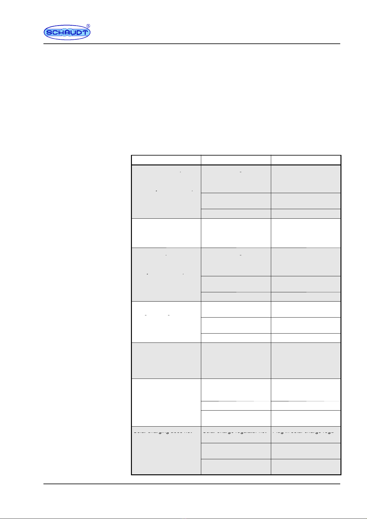
3.3 Faults
A flat battery or defective fuse is the cause of most faults in the power sup-
ply system.
If the battery is discharged, consumers can always be powered by starting
the engine of the base vehicle.
Please contact our customer service address if you cannot rectify the fault
using the following table.
If this is not possible, e.g. if you are abroad, you can have the electroblock
repaired at a specialist workshop. In this case, you must ensure that the
warranty is not invalidated by incorrect repairs being carried out. Schaudt
GmbH will not accept any liability for damage resulting from such repairs.
Fault Possible cause Remedy
Leisure area battery is not
h
d
d
i
2
3
0
V
No mains voltage Switch on the automatic
i
i
b
k
i
h
h
i
y
charged during 230V ope-
r
a
t
i
o
n
(
b
a
t
t
e
r
y
v
o
l
t
a
g
e
g
circuit breaker in the vehi-
c
l
e
;
c
h
e
c
k
t
h
e
m
a
i
n
s
v
o
l
-
r
a
t
i
o
n
(
b
a
t
t
e
r
y
v
o
l
t
a
g
e
constantly below 13.3 V)
c
l
e
;
c
h
e
c
k
t
h
e
m
a
i
n
s
v
o
l
-
tage
y
)
Too many consumers are
switched on
Switch off any consumers
not required
Defective electroblock Contact customer service
Living area battery is over-
charged during 230V ope-
ration (battery voltage
constantly above 14.5 V)
Defective electroblock Contact customer service
Starter battery is not char-
d
d
i
2
3
0
V
No mains voltage Switch on the automatic
i
i
b
k
i
h
h
i
y
ged during 230V opera-
t
i
o
n
(
b
a
t
t
e
r
y
v
o
l
t
a
g
e
c
o
n
-
g
circuit breaker in the vehi-
c
l
e
;
c
h
e
c
k
t
h
e
m
a
i
n
s
v
o
l
-
t
i
o
n
(
b
a
t
t
e
r
y
v
o
l
t
a
g
e
c
o
n
-
stantly below 13.0 V)
c
l
e
;
c
h
e
c
k
t
h
e
m
a
i
n
s
v
o
l
-
tage
y
)
Too many consumers are
switched on
Switch off any consumers
not required
Defective electroblock Contact customer service
Leisure battery is not
charged during mobile
t
i
(
b
t
t
l
t
Defective alternator Have the alternator chek-
ked
g
g
operation (battery voltage
below 13.0 V) No voltage on D+ input Have the fuse and cabling
checked
Defective electroblock Contact customer service
The leisure battery is
overcharged during mo-
bile operation (battery vol-
tage permanently above
14.3 V)
Defective alternator Have the alternator chek-
ked
The refrigerator does not
work during mobile opera-
tion
No power supply to the re-
frigerator
Have the fuse (20A of sup-
ply; possibly 2A of the D+
signal) and wiring checked
Defective electroblock Contact customer service
Defective refrigerator Havetherefrigeratorchek-
ked
Solar charging does not Solar charge regulator not Plug in solar charge regu-
S
o
l
a
r
c
h
a
r
g
i
n
g
d
o
e
s
n
o
t
work
S
o
l
a
r
c
h
a
r
g
e
r
e
g
u
l
a
t
o
r
n
o
t
plugged in
P
l
u
g
i
n
s
o
l
a
r
c
h
a
r
g
e
r
e
g
u
lator
Defective fuse or cabling Have the fuse and cabling
checked
Solar charge regulator de-
fective
Have solar charge regula-
tor checked
Flat vehicle fuses
Discharged battery --
start motor
Instruction Manual for Electroblock EBL 30 / EBL 30 with OVP
6Date: 15.10.2018 8110305 BA / EN
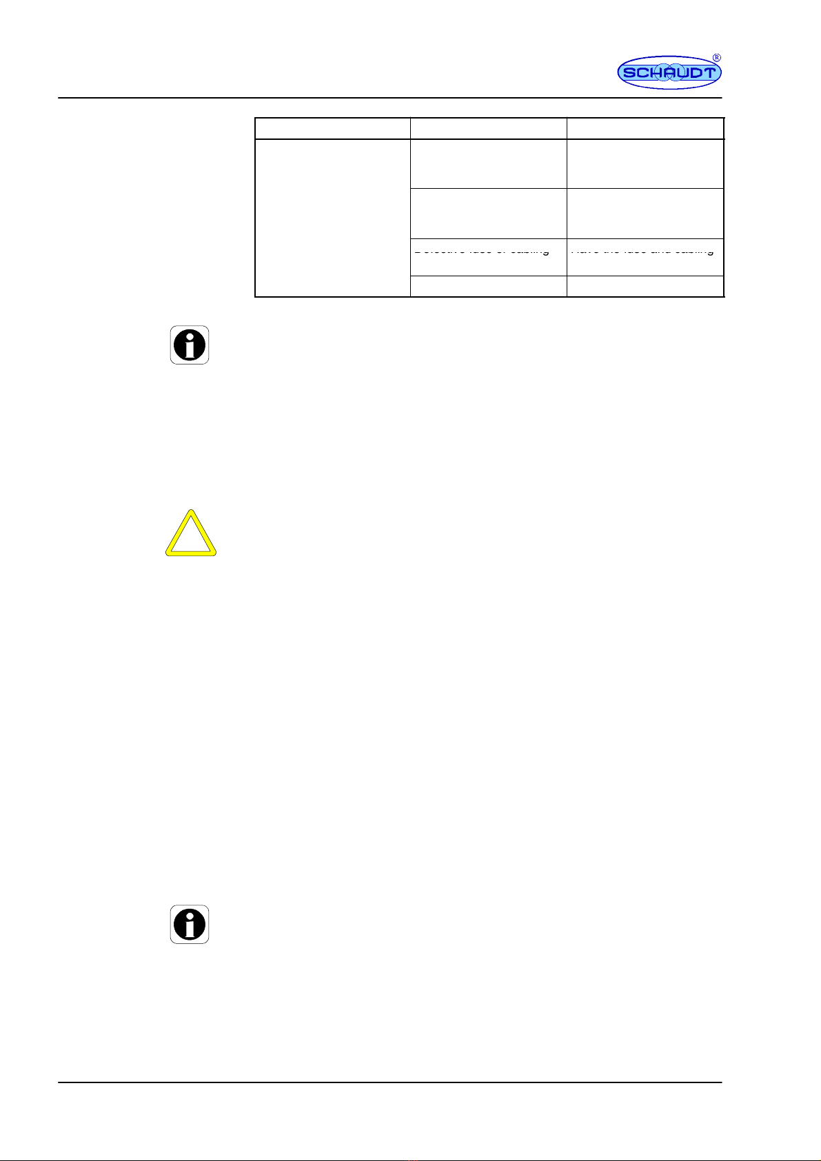
Fault RemedyPossible cause
12V supply does not work
i
n
t
h
e
l
e
i
s
u
r
e
a
r
e
a
12V main switch for the li-
v
i
n
g
a
r
e
a
b
a
t
t
e
r
y
i
s
s
w
i
t
12V main switch for the li-
v
i
n
g
a
r
e
a
b
a
t
t
e
r
y
m
u
s
t
b
e
i
nt
h
e
l
e
i
sure area v
i
ng area
b
attery
i
ssw
i
t-
ched off
v
i
ng area
b
attery must
b
e
switched on
Not all plugs/fuses are
p
l
u
g
g
e
d
i
n
t
o
t
h
e
e
l
e
c
t
r
o
Pug all plugs and fuses
(
c
o
r
r
e
c
t
r
a
t
i
n
g
s
)
i
n
t
o
t
h
e
p
l
ugge
d
i
nto t
h
ee
l
ectro-
block
(
correct rat
i
ngs
)
i
nto t
h
e
electroblock
Defective fuse or cabling Have the fuse and cabling
D
e
f
e
c
t
i
v
e
f
u
s
e
o
r
c
a
b
l
i
n
g
H
a
v
e
t
h
e
f
u
s
e
a
n
d
c
a
b
l
i
n
g
checked
Defective electroblock Contact customer service
YThe charging current is reduced automatically if the device becomes too
hot due to excessive ambient temperature or lack of ventilation. Always
prevent the device from overheating nevertheless.
YIf the automatic shutdown mechanism of the battery monitor is triggered,
fully charge the living area battery.
3.4 Closing down the system
The battery is isolated by switching off the battery cut-off switch.
YATTENTION!
Total discharge.
Damage to the leisure area battery:
FFully charge the living area battery before and after closing down the
system. (Connect vehicle to the mains with an 80Ah battery at least
12 hours and with a 160Ah battery at least 24 hours).
Disconnect the living area battery from the 12V power supply if the motor-
home is not used for a longer period (during the winter for example).
"Fully charge the living area battery before closing down the system.
"Switch off the main switch on the IT ... / LT ... control and display panel.
"Move the battery cut-off switch (see Fig. 4, Pos. 12) to the ”Battery OFF”
position. The following connections are isolated from the living area bat-
tery:
FAll 12V consumers
FFrost protection valve
FOperator and control panel
The living area battery is then protected against total discharge. This only
applies if the battery is intact. Follow the battery manufacturer’s instructions.
YIf the living area battery is isolated from the electroblock with the battery
cut-off, the frost protection valve of the combination heater opens. A loss
of water is possible (see the operating instructions for the combination
heater).
Closing down

Instruction Manual for Electroblock EBL 30 / EBL 30 with OVP
7
Date: 15.10.2018
8110305 BA / EN
4 Application and functions in detail
The EBL 30 electroblock is the central power supply unit for all 12V consu-
mers in the vehicle’s electrical system. It is usually located in a cupboard or
storage area and is accessible from the front in order to change fuses.
EBL 30
IT.../LT...
+--
+--
Control and
display panel
Electroblock
230V AC
12V consumers Leisure battery
Starter battery
Lighting
Pump
Heater
etc.
Fig. 2 On-board power supply system
The EBL 30 electroblock contains:
Fa charge module for charging all batteries connected
Fthe complete 12V distribution system
Ffuses for the 12V circuits
Fa battery monitoring module
Fcontrol and monitoring functions
An IT ... or LT ... control and switch panel must be connected for operation.
These devices control the electrical functions in the vehicle’s living area, inc-
luding accessories.
There is also an option to connect an additional charger and a solar loading
regulator.
Flat vehicle fuses protect the various circuits. The D+ output is an exception.
FExcess temperature
FOverload
FShort circuit
230V AC 10%, 47 to 63 Hz sinusoidal, protection class I
12V outputs may be loaded with max. 90% of the rated current of the re-
spective fuse (also see front panel).
Modules
System devices
Protective circuits of the
charging module
Mains connection
Current-carrying
capacity

Instruction Manual for Electroblock EBL 30 / EBL 30 with OVP
8Date: 15.10.2018 8110305 BA / EN
4.1 Battery functions
6-cell lead-gel or AGM batteries, 55 Ah and above
Simultaneous charging of the starter battery and the living area battery via
the alternator, parallel connection of the batteries via a cut-off relay
Maximum permitted charge current 14 A, fused with 15 A (for leisure area
battery), simultaneous charging of the starter battery
The battery is isolated with the battery cut-off switch.
This prevents the living area battery from slowly discharging due to closed
circuit current while the vehicle is not in use.
The switching option provided by the battery selector switch ensures opti-
mum charging of the battery types, lead-gel and AGM, for mains supply.
The battery monitor compares the current of the living area battery with a
reference current. As soon as the battery current drops below 10.5V, all 12V
consumers are switched off via main switch relays 1 and 2.
Only the frost protection valve continues to be powered.
The automatic disconnector is not triggered by short-term low voltage (shor-
ter than 2 seconds), caused by high current when switching on consumers.
If an overload or an insufficiently charged living area battery causes the vol-
tage to fall so low that the automatic disconnector is triggered, any non-es-
sential consumers should be switched off.
If need be, the 12V supply can begin operation for a short time. For this,
switch on the 12V main switch on the control and switch panel.
However, if the battery current remains below 11.0V, the 12V supply can not
be switched on again. Fully charge the living area battery as soon as possi-
ble. For more information, see the description of ”battery voltages”.
Suitable batteries
Battery charging
whilst moving
Battery charging via
solar charge regulator
Battery isolation
Battery selector switch
Automatic disconnector

Instruction Manual for Electroblock EBL 30 / EBL 30 with OVP
9
Date: 15.10.2018
8110305 BA / EN
4.2 Additional functions
This relay supplies the AES/compressor refrigerator with power from the
starter battery when the vehicle engine is running and the D+ connection is
live. An AES refrigerator is powered by the living area battery when the vehi-
cle engine is not running.
This feature provides an automatic max. 6 A float charge for the starter bat-
tery when the 230V mains is connected to the electroblock.
The electroblock is isolated from the mains within 10ms in the event of a
voltage greater than 265 V eff. The electroblock switches itself back on
again by itself after the mains voltage has attained the normal value.
5 Technical details
5.1 Mechanical details
130 x 275 x 170 (H x W x D in mm), including attachment feet
2.0 kg
PA (polyamide), gentian blue (RAL 5010)
Aluminium, powder coated, light grey (RAL 7035)
5.2 Electrical details
230V AC 10%, 47 -- 63 Hz sinusoidal, protection class I
1.9 A
6-cell lead-gel or AGM batteries, 55 Ah and above
Dependent on the control panel: approx. 5 -- 20 mA, plus consumption of
controller electronics of refrigerator
Conditions for the measurement:
Fapprox. 10 minutes after disconnection from the mains
F12.6 V battery voltage
FBattery alarm OFF
FBattery cut-off switch ON
FLighting for operator and control panel OFF
FAll consumers switched off
F12V main switch off
Loading of D+ output of the alternator by the electroblock approx. 0.5 mA
without current consumption on D+ point
12V outputs A maximum of 90% of the nominal
current of the relevant fuse may be
drawn.
Frost protection valve output max. 0.1 A
D+ point 1 A for fusing D+ input with 2 A
Automatic switch
function for
AES/compressor
refrigerator
Mains charging
starter battery
Overvoltage protection
fortheEBL30withOVP
Dimensions
Weight
Casing
Front
Mains connection
Current consumption
Suitable batteries
Standby current from
leisure battery
D+ loading
Current-carrying
capacity
Instruction Manual for Electroblock EBL 30 / EBL 30 with OVP
10 Date: 15.10.2018 8110305 BA / EN
Leisure battery
Battery selector
switch setting
lead-gel AGM
Charging curve IUoU IUoU
Final charge voltage 14,4V/16h 14,7 V / 4 h
Charge current 18 A 18 A
Voltage for float charge 13,7 V with automatic
switchover
13,7 V with automatic
switchover
Starter battery
Charging current float charge max. 6 A
Charging voltage typ. UWbat -- 0 . 2 V
New charge cycle for battery voltage < 13.7 V
Switchover to main charging with approx. 5 seconds delay
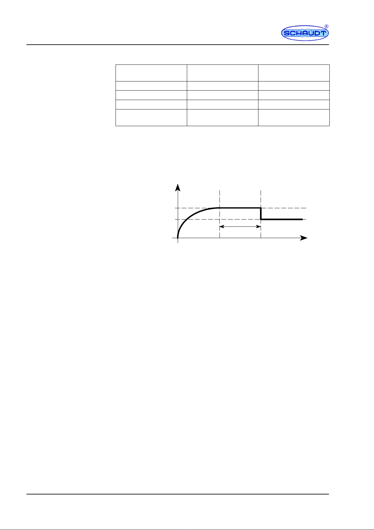
Main charge
I
Full charge
Uo
Trickle charge
U
16 h for lead-gel
4hforAGM
Time
Lead-gel:14.4V
AGM: 14.7 V
Ucharge
V
Lead-gel:13.7V
AGM: 13.7V
Fig. 3 Charging voltage curve with electroblock EBL 30
I Main charge with maximum 18 A charging current, electronically limi-
ted, up to final charging voltage. Start of charge also for completely
discharged batteries.
Uo Automatic switchover to full charge with constant 14.4 V (lead-gel) or
14.7 V (AGM). The duration of the full charge phase is based on the
battery type and is set on the device.
U Automatic changeover to compensation charge with constant 13.7 V. In
the compensation charge phase, the voltage at the output of the char-
ging module is constant.
Start of a new charging cycle by switching over to main charge, if the battery
voltage falls below 13.7 V for more than 5 seconds when loaded. Start of
charge also for completely discharged batteries. The internal charge module
can also be operated without leisure battery.
Overvoltage: Approx. 265 V eff.
This values applies for distortion-free sinusoidal voltage.
5.3 Environmental parameters
-20 Cto+45C
-20 Cto+70C
Operation in dry environment only
CE mark
Battery charging via
mains connector
Battery charging of the
starter battery
IUoU curve
Interrupting voltage for
EBL30withOVP
Operating temperature
Storage temperature
Humidity
CE

Instruction Manual for Electroblock EBL 30 / EBL 30 with OVP
11
Date: 15.10.2018
8110305 BA / EN
6Maintenance
The EBL 30 electroblock requires no maintenance.
Clean the electroblock with a soft, slightly damp cloth and mild detergent.
Never use spirit, thinners or similar substances. Do not allow liquids to enter
the electroblock.
No part of this manual may be reproduced, translated or copied without ex-
press written permission.
Cleaning
E

Instruction Manual for Electroblock EBL 30 / EBL 30 with OVP
12 Date: 15.10.2018 8110305 BA / EN
Appendix
A EC Declaration of Conformity
Schaudt GmbH hereby confirms that the design of EBL 30 electroblock com-
plies with the following relevant regulations:
The original EC declaration of conformity is available for reference at any
time.
Schaudt GmbH, Elektrotechnik & Apparatebau
Planckstraße 8
88677 Markdorf
Germany
B Special fittings/accessories
Schaudt IT ... / LT ... control and display panel (required for operation)
Schaudt battery charger LAS ... with max. 18 A charge current, including
suitable connection cable (MNL).
Schaudt Solar charge regulator type LR ... for solar modules with a total cur-
rent of 14A with 3-pole connection plug and connection cable
C Customer service
Schaudt GmbH, Elektrotechnik & Apparatebau
Planckstraße 8
88677 Markdorf, Germany
Phone: +49 7544 9577-16
Email: kundendienst@schaudt-gmbh.de
Web: www.schaudt-gmbh.de
Returning a faulty device:
"Complete and enclose the fault report, see Appendix D.
"Send it to the addressee (free delivery).
Manufacturer
Address
Panel
Additional charger
Solar charge regulator
Customer service
Send in device

Instruction Manual for Electroblock EBL 30 / EBL 30 with OVP
13
Date: 15.10.2018
8110305 BA / EN
D Fault report
In the event of damage, please fill in the fault report and send it with the
faulty device to the manufacturer.
Device type: _______________________
Item no.: _______________________
Vehicle: Manufacturer: _______________________
Model: _______________________
Own installation? Yes -No -
Upgrade? Yes -No -
Following fault has occurred (please tick):
-Electrical consumers do not work -- which?
(please specify below)
-Switching on and off not possible
-Persistent fault
-Intermittent fault/loose contact
Other comments:

Instruction Manual for Electroblock EBL 30 / EBL 30 with OVP
14 Date: 15.10.2018 8110305 BA / EN
E Layout
11
34 56 7
28
12
9
13
1
14
10
Fig. 4 Layout of the EBL 30 electroblock (front)
1 Mains cable with WAGO plug connector
2 Connection block, solar regulator
3 Connection block, refrigerator
4 Connection block, refrigerator supply D+, battery sen-
sor/control lines
5 Connection block, frost protection valve, heating and
floor light/steps
6 IT ... / LT ... control and display panel connector
7 Connection block spare 2, sockets 2 floor light 4A and
4B/radio
8 Connection block, additional charger
9 Connection block TV, pump, sockets 1,
spare 1, circuits 1 and 2
10 Lead-gel / AGM battery changeover switch
11 Flat vehicle fuses
12 Battery cut-off switch
13 Housing
14 Assembly flaps
123
Fig. 5 Layout of the EBL 30 electroblock (rear)
1 Connection, living area battery
2 Earth connector
3 Connection, starter battery
Instruction Manual for Electroblock EBL 30 / EBL 30 with OVP
15
Date: 15.10.2018
8110305 BA / EN
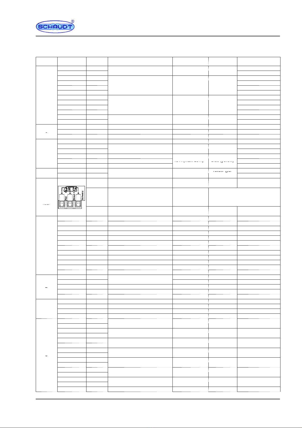
F Connector assignment
Block Pin Signal Use Fuse Colour code Comment
9 +
F
l
o
o
r
l
i
g
h
t
4
B
/
r
a
d
i
o
1
5
A
(
m
a
x
1
5
A
)
B
l
u
e
(
b
l
u
e
)
12 --
F
l
oor
l
i
g
h
t4
B
/
ra
d
i
o
1
5
A
(
ma
x
.
1
5
A
)
B
l
ue
(
b
l
ue
)
1 +
4 +
F
l
o
o
r
l
i
g
h
t
4
A
2
5
A
(
m
a
x
2
5
A
)
W
h
i
t
e
(
w
h
i
t
e
)
5--
F
l
oor
l
i
g
h
t4
A
2
5
A
(
ma
x
.
2
5
A
)
W
h
i
te
(
w
h
i
te
)
5
10 --
52 +
3 +
S
o
c
k
e
t
s
2
1
0
A
(
m
a
x
2
5
A
)
R
e
d
(
w
h
i
t
e
)
7--
S
oc
k
ets
2
1
0
A
(
ma
x
.
2
5
A
)
R
e
d
(
w
h
i
te
)
8--
6 +
S
p
a
r
e
2
1
0
A
(
m
a
x
1
5
A
)
R
e
d
(
b
l
u
e
)
11 --
S
pare
2
1
0
A
(
ma
x
.
1
5
A
)
R
e
d
(
b
l
ue
)
3WB Solar charging, living area battery 15 A blue
62SB Solar charging, starter battery -- --
6
1-- Negative, solar charger -- --
4 + Frost protection valve PTC 250 mA --
1 +
H
e
a
t
e
r
1
0
A
(
m
a
x
1
5
A
)
R
e
d
(
b
l
u
e
)
4
5--
H
eater
1
0
A
(
ma
x
.
1
5
A
)
R
e
d
(
b
l
ue
)
42 + Floor light
3 + Step 15 A (max. 20 A) Blue (yellow)
6-- Floor light/step
1
5
A
(
m
a
x
.
2
0
A
)
B
l
u
e
(
y
e
l
l
o
w
)
7
2 +
A
u
x
i
l
i
a
r
y
c
h
a
r
g
e
r
2
0
A
(
m
a
x
2
0
A
)
Yellow (yel-
71--
A
ux
i
l
i
ary c
h
arger
2
0
A
(
ma
x
.
2
0
A
)
Y
e
l
l
o
w
(
y
e
l
low)
+Red Positive, starter battery 50 A Red External fuse
(maxi fuse)
Screw--
type ter-
minal,
rear
-- B r o w n Leisure battery negative --
The negative terminal of the leisure
area battery must be connected
externally to the negative terminal of
the starter battery
r
e
a
r
+Black Positive, living area battery 50 A Red External fuse
(maxi fuse)
6Mains indicator
4Shunt battery Polyswitch 2.5 A -- Internal
1Shunt consumer Polyswitch 2.5 A -- Internal
912V ON
12 12V OFF
3
512V indicator Polyswitch 2.5 A -- Internal
3
2Negative leisure area bat. sensor
11 + Leisure battery sensor
8+ Starter battery Polyswitch 2.5 A -- Internal
3Not assigned
7Not assigned
10 Not assigned
5 +
L
e
i
s
u
r
e
b
a
t
t
e
r
y
s
e
n
s
o
r
2A Grey External fuse
2--
L
e
i
sure
b
attery sensor -- --
21 + Starter battery for refrigerator 20 A Yellow External fuse
2
3D+ Engine running 2A Grey External fuse
4-- Starter battery for refrigerator
4 + Compressor/AES refrigerator -- --
1
1 + Absorber refrigerator -- --
1
2D+ Output D+ -- --
3-- Refrigerator
6 +
T
V
1
0
A
(
m
a
x
1
0
A
)
R
e
d
(
r
e
d
)
12 --
T
V
1
0
A
(
ma
x
.
1
0
A
)
R
e
d
(
re
d
)
9 +
P
u
m
p
7
5
A
(
m
a
x
1
0
A
)
B
r
o
w
n
(
r
e
d
)
14 --
P
ump 7.5
A
(
ma
x
.
1
0
A
)
B
rown
(
re
d
)
2 +
C
i
r
c
u
i
t
1
1
5
A
(
m
a
x
1
5
A
)
B
l
u
e
(
b
l
u
e
)
8--
C
i
rcu
i
t
1
1
5
A
(
ma
x
.
1
5
A
)
B
l
ue
(
b
l
ue
)
3 +
C
i
r
c
u
i
t
2
1
5
A
(
m
a
x
1
5
A
)
B
l
u
e
(
b
l
u
e
)
810 --
C
i
rcu
i
t
2
1
5
A
(
ma
x
.
1
5
A
)
B
l
ue
(
b
l
ue
)
8
7 +
S
o
c
k
e
t
s
1
1
0
A
(
m
a
x
1
5
A
)
R
e
d
(
b
l
u
e
)
13 --
S
oc
k
ets
1
1
0
A
(
ma
x
.
1
5
A
)
R
e
d
(
b
l
ue
)
4 +
M
u
l
t
i
m
e
d
i
a
1
0
A
(
m
a
x
1
5
A
)
R
e
d
(
b
l
u
e
)
11 --
M
u
l
t
i
me
d
i
a
1
0
A
(
ma
x
.
1
5
A
)
R
e
d
(
b
l
ue
)
1 +
S
p
a
r
e
1
1
0
A
(
m
a
x
1
5
A
)
R
e
d
(
b
l
u
e
)
5--
S
pare
1
1
0
A
(
ma
x
.
1
5
A
)
R
e
d
(
b
l
ue
)
15 n.a. --
Instruction Manual for Electroblock EBL 30 / EBL 30 with OVP
16 Date: 15.10.2018 8110305 BA / EN
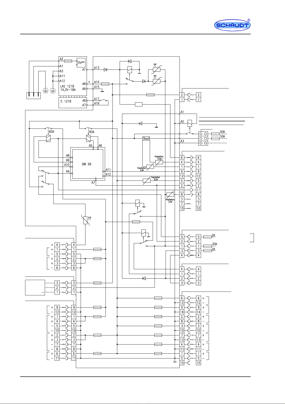
G Block diagram/wiring diagram
Mains 230V~50Hz
WAGO connector Changeover switch
Lead-gel
AGM
Main switch relay
(for shutting down/battery monitor)
Main switch relay
for 12V ON/OFF)
Charging relay
starter battery
MNL -connector sockets 2F -BL7
+ Auxiliary charger
Negative charger
Battery cut-off relay
The negative pole of the living area battery
must be connected externally to the
negative pole of the starter battery.
+ starter battery (batt. 1)
+ living area battery (batt. 2)
Leisure battery negative
E20--3F
MR -pin socket 12 F -block 3
Mains indicator
Shunt battery
Shunt consumer
12 V ON
12 V OFF
12V control
Negative sensor leisure area battery (batt. 2)
+ sensor living area battery (batt. 2)
+ starter battery (batt. 1)
Not assigned
Not assigned
Not assigned
* Refrigerator lines must be routed separated from further
battery lines to the battery poles.
MNL-connector sockets 5F-Block
2
+ Leisure battery sensor
Negative leisure area battery sensor
+ Starter battery for refrigerator *
D+ input
Negative starter battery for refrigerator *
MNL connector socket 4F-Block 1
1.5 mm2
each
Max. 10 m
+ compressor/AES- refrigerator
+ Absorber refrigerator *
D+ point
Negative, refrigerator
MNL-connector sockets 15F-Block 8
TV
Pump
Circuit 1
Circuit 2
Sockets 1
Multimedia
Spare 1
Not assigned
MNL-connector sockets 6F-Block
4
Frost protection valve
Heater
Floor
light/step
MNL-connector sockets 3F-Block 6
Solar-
charge-
regulator
MNL-connector sockets 12F-Block 5
Floor light 4A
Sockets 2
Spare 2
Floor light 4B/radio
Batterycut-
off switch
(off)
* Only for EBL 30 with OVP
SB
WB
Refrigerator relay
Refrigeratorrelay
EBL 30
10A*
15A*
15A
15A*
25A*
10A*
10A*
10A*
7.5A*
15A*
15A*
10A*
10A*
10A*
20A*
20A
20A
* Default values, see Table 15 for maximum values
This manual suits for next models
1
Table of contents
Other Schaudt Power Supply manuals


