manuals.online logo
Brands
  1. Home
  2. •
  3. Brands
  4. •
  5. LEYBOLD
  6. •
  7. Power Supply
  8. •
  9. LEYBOLD 521 50 User manual

LEYBOLD 521 50 User manual

Physik Chemie ⋅Biologie Technik LEYBOLD DIDACTIC GMBH
3/97-Pr/Sf-
Gebrauchsanweisung 521 50
Instruction Sheet
This device supplies a continuously adjustable DC voltage
which is stabilized with respect to voltage (0...15 V) and current
(0...5 A), and can be used as a constant-voltage or constant-
current source. Two LED digital displays allow you to monitor
the voltage level and current consumption simultaneously.
Additionally, an AC voltage output which is electrically isolated
from the DC voltage output and has a maximum load capacity
of 5 A is provided, which can be set from 2 V to 15 V in seven
steps.
1 Safety notes
2 Technical data, description
1
Mains switch with on-indicator lamp
2
Display unit with 2 1/2 digit display forDC voltage at output
6
; measuring range: 0 to 15 V
accuracy of voltage meter: ±1 % of upper range value
3
Display unit with 2-digit display for direct current at out-
put
6
;
measuring range: 0 to 5 A
accuracy of ammeter: ±6 % of upper range value
4
Adjustment knob for DC voltage at output
6
;
constant-voltage operation indicated by LED (4.1) (see
section 3.1)
5
Adjustment knob for direct current at output
6
;
constant-current operation indicated by LED (5.1) (see
section 3.2)
Das Gerät liefert in Spannung (0...15 V) und Strom (0...5 A)
stabilisierte und stufenlos einstellbare Gleichspannung; es
kann als Konstantspannungs- oder als Konstantstromquelle
eingesetzt werden. Zwei LED-Digitalanzeigen ermöglichen die
gleichzeitige Kontrolle der Spannung und der Stromentnahme.
Außerdem steht an einem galvanisch vom Gleichspannungs-
ausgang getrennter Ausgang bis 5 A belastbare Wechselspan-
nung zur Verfügung, die in 7 Stufen von 2 V bis 15 V eingestellt
werden kann.
1 Sicherheitshinweise
2 Technische Daten, Beschreibung
1
Netzschalter mit Betriebanzeigeleuchte
2
Display mit 2 1/2-stelliger Digitalanzeige für die Gleichspan-
nung an Ausgang
6
;
Meßbereich: 0 bis 15 V
Genauigkeit des Spannungsmessers: ±1 % vom Endwert
3
Display mit 2-stelliger Digitalanzeige für den Gleichstrom
an Ausgang
6
;
Meßbereich; 0 bis 5 A
Genauigkeit des Strommessers: ±6 % vom Endwert
4
Stellknopf für Gleichspannung an Ausgang
6
;
Anzeige des Konstantspannungsbetriebs mit LED (4.1)
(siehe Abschnitt 3.1)
5
Stellknopf für den an Ausgang
6
entnehmbaren Gleich-
strom;
Anzeige des Konstantstrombetriebs mit LED (5.1) (siehe
Abschnitt 3.2)
AC/DC Netzgerät 0 ... 15 V
AC/DC Power Supply 0...15 V
Fig. 1
•Nach Ansprechen des Überstromschutzschalters
8
– an-
gezeigt durch Herausspringen des Sicherungsknopfes –
Gerät am Netzschalter
1
abschalten; Schaltungsfehler
bzw.Ursache der Überlastung beseitigen; danach Si-
cherungsknopf drücken und Gerät wieder einschalten.
•Falls der auf dem Leistungsschild (Gehäuse-Rückseite)
aufgedruckte Wert für die Netzanschlußspannung von
dem ortsüblichen Wert abweicht, Gerät zum Umrüsten in
transportgerechter Umverpackung an Leybold Didactic
schicken.
•When the overcurrent circuit breaker
8
is actuated – indi-
cated when the fuse button pops out – switch off the device
using mains switch
1
; eliminate the circuit error or cause
of the overload, then press the fuse button back in and
switch the device back on.
•If the mains voltage value given on the rating plate (rear of
device) is different from your local mains value, pack the
device in appropriate transport packaging and return it to
Leybold Didactic for conversion.
6
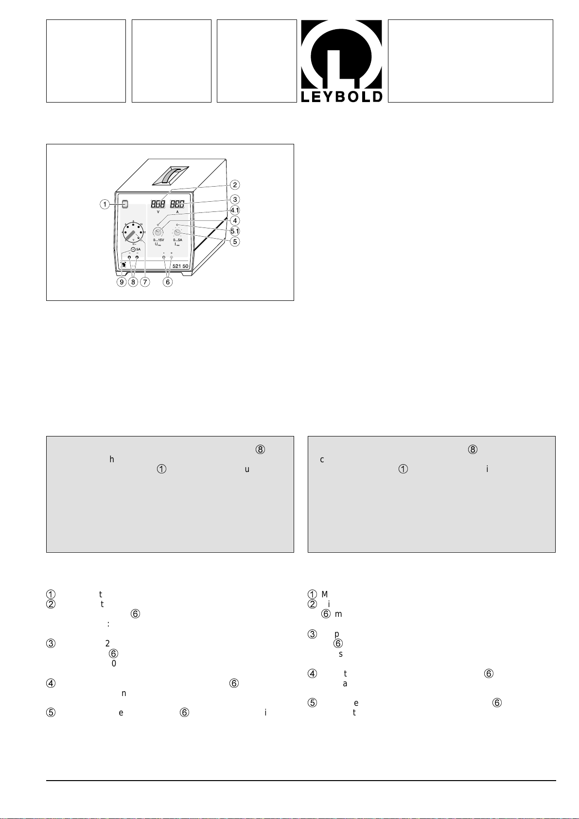
Ausgang für Gleichspannnung und -strom,
elektronisch geregelt und stufenlos einstellbar von
- 0 bis 15 V mit Stellknopf
4
und
- 0 bis 5 A mit Stellknopf
5
Restwelligkeit bei Vollast: ≤50 mVss
Stabilisierung bei Vollast: < 0.2 % vom Endwert
bei ±10 % Netzspannungs-
schwankung: < 0.2 % vom Endwert
Restspannung in Nullstellung: < 0.2 % vom Endwert
7
Umschalter (Steckbrücke) zum stufenweisen Einstellen der
WechselspannunganAusgang
9
auf2, 4, 6, 8, 10, 12und15V
8
Überstromschutzschalter 5 A, thermisch-magnetisch ab-
schaltend bei einer Stromentnahme von mehr als 5 A am
Wechelspanningsausgang
9
9
Ausgang für die mit Umschalter
7
gewählte Wechelspan-
nung
Auf der Gehäuse-Rückseite Steckerwanne mit integriertem Si-
cherungshalter für Primär- und Reservesicherung.
Netzanschlußkabel im Lieferumfang enthalten.
Im Gehäuse-Boden 2 ausklappbare Füße zum Neigen des Ge-
rätes.
Weitere technische Daten
Ausgänge:
- erdfrei, kurzschlußfest, galvanisch voneinander getrennt und
fremdspannungsfest
Farbkennung der Sicherheitsbuchsen:
- Gleichspannungsausgang: blau (Minuspol)
rot (Pluspol)
- Wechselspannungsausgang: schwarz
Sicherung: - Primärseite: Schmelzsicherung
Wert siehe Sicherungs-
schild auf der Gehäuse-
Rückseite
- Sekundärseite: Überstromschutzschalter
5 A, thermisch-magnetisch
abschaltend, für Ausgang
9
Netzanschlußspannung 230 V
"
; 50/60 Hz bzw.
115 V
"
(gemäß Leistungs-
schild auf der Gehäuse-
Rückseite)
Leistungsaufnahme: 225 VA
Abmessungen: 20 cm x 21 cm x 23 cm
Masse: 8,0 kg
3 Bedienung
3.1 Betrieb als Konstantspannungsquelle
Stellknopf
5
für die Strombegrenzung auf maximal stellen. Die
LED (4.1) für Konstantspannungsbetrieb leuchtet auf. Durch
Betätigen des Stellknopfes
4
den gewünschten Spannungs-
wert einstellen, der im Display
2
angezeigt wird.
Option
:
Soll zusätzlich der maximal entnehmbare Strom zum Schutz
der angeschlossenen Geräte auf Werte unter 5 A begrenzt wer-
den, so ist nun ohne angeschlossene Schaltung bei kurzge-
schlossenem Ausgang
6
(z.B. mittels Brückenstecker) der
Stellknopf
5
für die Strombegrenzung soweit zurückzudrehen,
bis der gewünschte Maximalstrom fließt (Display
3
sowie LED
(5.1)). Sodann die Spannung mit Stellknopf
5
wieder auf Null zu-
rückdrehen, den Kurzschluß entfernen und den Ausgang
6
wie-
der mit der Schaltung verbinden. Bei Erhöhen der Spannung mit
Stellknopf
4
kann nun – unabhängig vom angeschlossenen Ver-
braucher – kein Strom entnommen werden, der größer ist als der
eingestellte Grenzwert. Mit einsetzender Strombegrenzung leuch-
tet die LED (5.1) auf, eine weitere Erhöhung der Spannung mit
demStellknopf
4
ist nicht möglich.
6
Output for DC voltage and current;
electronically stabilized and continuously adjustable from
- 0 to 15 V using adjustment knob
4
and
- 0 to 5 A using adjustment knob
5
Residual ripple at full load ≤50 mVpp
Stabilization at full load < 0.2 % of upper range value
at ±10 % mains voltage
fluctuation < 0.2 % of upper range value
Residual voltage in
zero position < 0.2 % of upper range value
7
Changeover system (jumper) for step-by-step setting of AC
voltage at output
9
to 2, 4, 6, 8, 10, 12 and 15 V
8
Overcurrent circuit breaker 5 V, thermomagnetic cutout at
current consumption above 5 A at AC voltage output
9
9
Output for AC voltage selected using changeover system
7
.
Appliance-plug connector with integrated holder for primary
and spare fuse on rear of device.
Mains connection cable included in scope of supply.
Two folding feet in bottom of housing for inclining the device.
Additional technical data
Outputs
- floating, short-circuit proof, electrically isolated from each
other and proof against interference voltage
Color coding of safety sockets:
- DC voltage output blue (minus pole)
red (plus pole)
- AC voltage output: black
Protection: - Primary side: Fuse
refer to the fuse rating plate
on the rear of the device for
the fuse rating
- Secondaryside:Overcurrent circuit breaker
5 A, thermomagnetic cut-
out, for output
9
Mains voltage 230 V AC; 50/60 Hz or
115 V AC (according to ra-
ting plate on rear of device)
Power consumption: 225 VA
Dimensions: 20 cm x 21 cm x 23 cm
Weight: 8.0 kg
3Operation
3.1 Using the device as a constant-voltage source
Set the current-limiting knob
5
to the maximum position. LED
(4.1) lights up, indicating that the device is operating in con-
stant-voltage mode. Set the desired voltage value using knob
4
; the value appears in display
2
.
Option:
If you also want to limit the maximum current consumption to
values below 5 A in order to protect the connected apparatus,
disconnect the power supply from the circuit, short output
6
(e.g. using a bridging plug) and turn the current-limiting knob
5
down until the desired maximum current is flowing (display
3
and LED (5.1)). Then reduce the voltage to zero with knob
5
,
remove the short-circuit and reconnect output
6
to the circuit.
Now, when you increase the voltage with knob
4
, no current
greater than the set limit value can flow regardless of the con-
nected load. When current limiting is activated, LED (5.1) lights
up, and it is not possible to increase the voltage with knob
4
.
2
LEYBOLD DIDACTIC GMBH ⋅Leyboldstrasse 1 ⋅D-50354 Hürth ⋅Phone (02233) 604-0 ⋅Telefax (02233) 604-222 ⋅ Telex 17 223 332 LHPCGN D
©byLeyboldDidacticGmbH, PrintedintheFederalRepublicofGermany
Technical alterations reserved
3.2 Betrieb als Konstantstromquelle
Stellknopf
4
für die Spannungsbegrenzung auf maximal stel-
len. Die LED (5.1) für Konstantstrombetrieb leuchtet auf. Durch
Betätigen des Stellknopfes
5
den gewünschten Strom einstel-
len, der im Display
3
angezeigt wird.
Option
:
Soll zusätzlich die maximal einstellbare Spannung zum Schutz
der angeschlossenen Geräte auf Werte unter 15 V begrenzt
werden, so ist mit offenem Ausgang
6
der Stellknopf
4
für die
Spannungsbegrenzung soweit zurückzudrehen, bis die ge-
wünschte Maximalspannung erreicht ist (Display
2
sowie LED
(4.1)). Sodann den Strom mit Stellknopf
4
wieder auf Null zu-
rückdrehen und den Ausgang
6
mit der Schaltung verbinden.
Bei Erhöhen des Stromes mit Stellknopf
5
kann nun – unab-
hängig vom angeschlossenen Verbraucher – keine Spannung
für Ausgang
6
eingestellt werden, die größer als der einge-
stellte Grenzwert. Mit einsetzender Spannungsbegrenzung
leuchtet die LED (4.1) auf und eine weitere Erhöhung der Stro-
mes mit dem Stellknopf
5
ist nicht möglich.
4 Austausch der Primärsicherung
Wert siehe Sicherungsschild auf der Gehäuse-Rückseite
Einsatz
a
mit Fassung für Primärschmelzsicherung
b
und Re-
servesicherung
c
heraushebeln (Fig. 2.1).
Defekte Sicherung
b
entfernen und durch die auf richtigen Si-
cherungswert überprüfte Reservesicherung
c
ersetzen (Fig.
2.2).
Neue Sicherung als Reservesicherung
c
einsetzen und Ein-
satz
a
wieder einschieben.
3.2 Using the device as a constant-current source
Set the voltage-limiting knob
4
to the maximum position. LED
(5.1) lights up, indicating that the device is operating in con-
stant-current mode. Set the desired current value using knob
5
; the value appears in display
3
.
Option:
If you also want to limit the maximum voltage to values below
15 V in order to protect the connected apparatus, make sure
output
6
is open and turn the voltage-limiting knob
4
down
until the desired maximum voltage is flowing (display
2
and
LED (4.1)). Then reduce the current to zero with knob
4
and
connect output
6
to the circuit. Now, when you increase the
current with knob
5
, no voltage greater than the set limit value
can flow regardless of the connected load. When voltage li-
miting is activated, LED (4.1) lights up, and it is not possible to
increase the current with knob
5
.
4 Replacing the primary fuse
See fuse plate on rear of device for correct rating
Pry out insert
a
with holder for primary fuse
b
and spare fuse
c
(Fig. 2.1).
Remove the defective fuse
b
and replace it with the spare fuse
c
which has been checked for the correct rating (Fig. 2.2).
Insert a new fuse as the reserve fuse
c
and slide insert
a
back
into the device.
Fig. 2.2Fig. 2.1

Other LEYBOLD Power Supply manuals

LEYBOLD TURBO.POWER 300 User manual

LEYBOLD

LEYBOLD TURBO.POWER 300 User manual

LEYBOLD 666 471 User manual

LEYBOLD

LEYBOLD 666 471 User manual

LEYBOLD 737 01 User manual

LEYBOLD

LEYBOLD 737 01 User manual

LEYBOLD TURBO.POWER 800 User manual

LEYBOLD

LEYBOLD TURBO.POWER 800 User manual

LEYBOLD 521 55 User manual

LEYBOLD

LEYBOLD 521 55 User manual

Popular Power Supply manuals by other brands

Honeywell 9007AX01 installation instructions

Honeywell

Honeywell 9007AX01 installation instructions

Pyle Pro PDBC60 owner's manual

Pyle Pro

Pyle Pro PDBC60 owner's manual

Akyga AK-CH-16 user manual

Akyga

Akyga AK-CH-16 user manual

ZALMAN ZM1000-HP user manual

ZALMAN

ZALMAN ZM1000-HP user manual

Vertiline Vertiline8i installation guide

Vertiline

Vertiline Vertiline8i installation guide

Danfysik SYSTEM 9100 user manual

Danfysik

Danfysik SYSTEM 9100 user manual

GW Instek PSW Series Programming manual

GW Instek

GW Instek PSW Series Programming manual

PowerBox Camtec OSW00301 quick start guide

PowerBox

PowerBox Camtec OSW00301 quick start guide

Sonnen SonnenProtect 1300-AU-IN-ATS installation instructions

Sonnen

Sonnen SonnenProtect 1300-AU-IN-ATS installation instructions

Farmcomp OLLI 122B operating manual

Farmcomp

Farmcomp OLLI 122B operating manual

Sherlotronics 3.2AMP installation instructions

Sherlotronics

Sherlotronics 3.2AMP installation instructions

Lake Shore 102 user manual

Lake Shore

Lake Shore 102 user manual

R&S NGE100B Series user manual

R&S

R&S NGE100B Series user manual

Pulsar Black Power PSBEN 1024B/LCD manual

Pulsar

Pulsar Black Power PSBEN 1024B/LCD manual

GW Instek PSU Series user manual

GW Instek

GW Instek PSU Series user manual

Dynatronix LT1200X SERIES operating manual

Dynatronix

Dynatronix LT1200X SERIES operating manual

CDVI BS60 installation manual

CDVI

CDVI BS60 installation manual

Hameg HM7044 user manual

Hameg

Hameg HM7044 user manual

manuals.online logo
manuals.online logoBrands
  • About & Mission
  • Contact us
  • Privacy Policy
  • Terms and Conditions

Copyright 2025 Manuals.Online. All Rights Reserved.