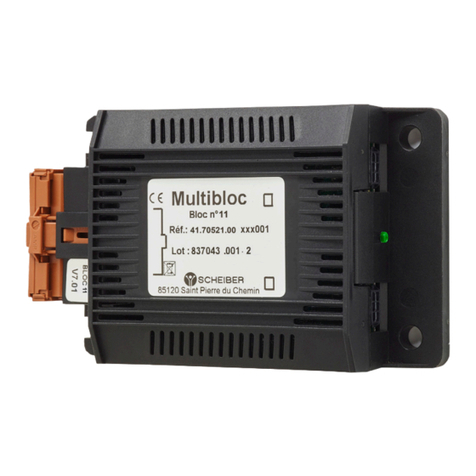
Scheiber BLOC 10 User manual

L’innovation française depuis 1965
SCHEIBER
2 Bellevue, 85120 Saint-Pierre du Chemin •France
Phone : +33 (0)2 51 51 73 21 •clients@scheiber.fr •sav@scheiber.fr •www.scheiber.fr
Domotique embarquée
Embedded home automation
User Manuel & Troubleshooting Guide
BLOC 10
Ref : 41.70520.00 XXX XXX
Acknowledgement...................................................P.2
Safety Warnings.........................................................P.2
Accessories / Associated references.................P.2
Equipment description..........................................P.2
Technical characteristics........................................P.3
Electrical characteristics.........................................P.3
Description of the markings used.....................P.3
Installation instructions..........................................P.5
Connection..................................................................P.5
Wiring............................................................................P.6
Terms and conditions.............................................P.7
Warranty terms.........................................................P.7

L’innovation française depuis 1965
P. 2
L’innovation française depuis 1965
Designation Reference
120Ω BUS CAN Termination 0D.CRD399
Crimp contacts and 21-point MCP connector 62.SAC12003A.00
Bloc 10 allows 6 momentary switches to be interfaced with a status indicator and a backlight indicator per function.
It interfaces with a Scheiber Multibloc network, in order to retrieve the state of the control switch and to deport the control to a
power block (Bloc 9 for example).
Acknowledgement
We thank you for your purchase and hope that you are fully satised with this product.
Before you use this product, we recommend you read the instructions below carefully.
This manual explains how to use and install the product in accordance with its intended use.
Safety Warnings
WARNING: Do not disassemble the device
Any contact with the product's internal components can cause injury. In the event of a malfunction, only a qualied technician is
authorised to repair the device
WARNING: In the event of impact
If the product falls or undergoes heavy impact, immediately contact a qualied person to ensure the device is working correctly
WARNING: Unpacking the equipment
After unpacking the product, make sure that it is complete and in good condition. If you are not sure, immediately contact a person
with the required professional qualication
WARNING: Unpacking the equipment
Do not leave any part of the packaging within the reach of children or vulnerable adults
Equipment description
Accessories / Associated references

L’innovation française depuis 1965
P. 3
L’innovation française depuis 1965
INPUT RATED VOLTAGE (VDC)8-32 VDC
SELF-CONSUMPTION 45 mA
MAXIMUM CURRENT PER OUTPUT 0,7A
MAXIMUM CUMULATIVE CURRENT 5A
OUTPUT INDICATORS DISJUNCTION THRESHOLD 0,7A
BLOC 10
REFERENCE 41.70520.00 XXX XXX
POWER SUPPLY 8-32 V DC
DETAILS AND FEATURES OF THE INPUTS 6 minus digital inputs (for momentary switches)
DETAILS AND FEATURES OF THE OUTPUTS
6 outputs MOS 0,7A 0-32VDC
for switch status indicators
1 output MOS 0,7A 0-32VDC
for switch backlight indicators
CAN BUS 2 x connectors type 6-way Micro-Fit
ENVIRONMENTAL CONDITIONS
Indoor use
Altitude up to 2000m
Operating temperature: 0 to +50 °C
Relative humidity: 0 to 93% - non-condensing
Protection index: IP20
MOUNTING 4 screws
MOUNTING DISTANCE 100 x 59 mm
WEIGHT 0,19 Kg
STANDARDS EN 60945
FIRMWARE VERSION V8.00 or higher
DIMENSIONS (LxWxH)160 x 95 x 50 mm
Technical characteristics
Electrical characteristics
Description of the markings used
VVolt
AAmpere
ou DC Direct current

L’innovation française depuis 1965
P. 4
L’innovation française depuis 1965
Seen from above
Left side view
Right side view
CAN BUS
CAN BUS
TYCO 21-pin
Connector
CAN BUS CAN BUS
TYCO 21-pin
Connector
STATUS LED

L’innovation française depuis 1965
P. 5
L’innovation française depuis 1965
INPUT / OUTPUT / POWER SUPPLY
Type of connection
Cross section
MCP2,8 - 21Pts (BROWN) housing connectors
Ref. Scheiber 0E.CON1430
Ref. Tyco 8-968975-1 MCP2,8GEH21P
MCP2,8 Receptacle 0,5-1,0mm2 tinned
Ref. Scheiber 0E.CLP360
Ref. Tyco 1-968849-1
Extraction tool for MCP contacts
Réf. Tyco 1-1579007-2
CAN BUS 2 x CAN connectors type 6-way Micro-Fit
PROTECTION TO BE PROVIDED ON THE SUPPLY LINE
Protection rating
Protection location
Fuse or circuit breaker 5A
Accessible and identied for the user
Connection
Mounting
Mounting distance :
100 x 59 mm
36,31
77,51
119,50
59
100
Inpout 1 ... 6 (-)
Output 1 ... 6 (+)
Output 7 (+)
*
* To power a backlight indicator for example
17 Coding
19
21
BLOC 10
Illuminated push-button
Installation instructions
• This device must be placed in a place protecting it from any risk of water splashing. Install in a ventilated location
• Do not install on supports that are sensitive to heat, such as carpet or PVC ooring, etc.
• The product must be installed away from heat and humidity
!WARNING: Connection/disconnection with power on
Do not perform connection or disconnection with power on.

L’innovation française depuis 1965
P. 6
L’innovation française depuis 1965
Crimp pin Designation Description
1 S1 Output + indicator N°1
2 / NC
3E1_NUM_MOINS Minus digital input for momentary switches N°1
4 S2 Output + indicator N°2
5 / NC
6E2_NUM_MOINS Minus digital input for momentary switches N°2
7 S3 Output + indicator N°3
8 / NC
9E3_NUM_MOINS Minus digital input for momentary switches N°3
10 S4 Output + indicator N°4
11 / NC
12 E4_NUM_MOINS Minus digital input for momentary switches N°4
13 S5 Output + indicator N°5
14 / NC
15 E5_NUM_MOINS Minus digital input for momentary switches N°5
16 S6 Output + indicator N°6
17 Coding Coding input
18 E6_NUM_MOINS Minus digital input for momentary switches N°6
19 + BAT Power supply input 8-32VDC
20 S7 Output + backlight indicator
21 MASS Battery mass
Wiring
1
2
Connect to each connector:
- either a CAN connection cable
(to another Multibloc compatible device)
- or a 120Ω impedance matching plug.
Connect the equipment to the pins according to the numbering available in the table below, then plug
the MPC connector into the TYCO receptacle.
or
120Ω
Termination
CAN
cable
CAN
cable
CAN
cable
1
2
3
4
5
6
7
8
9
10
11
12
13
14
15
16
17
18
19
20
21
TYCO receptacleMCP connectorcrimp pins x21

L’innovation française depuis 1965
P. 7
L’innovation française depuis 1965
Terms and conditions
The manufacturer cannot be held responsible and accepts no responsibility in the event of harm to persons or property due to
improper use and in reference to the warnings provided in this manual.
SCHEIBER reserves the right to change the characteristics of its products in the interest of its customers. The manual supplied with this
product must not be reproduced, transmitted, stored in a search system or translated into any language, in full or in part, by any means,
without the prior written consent of SCHEIBER.
Although every effort has been made to provide you full and accurate information in this manual we ask that you inform the SCHEIBER
representative of your country in case of any error or omission we may have overlooked.
SCHEIBER reserves the right to change the characteristics of the hardware and software described in these manuals at any time and
without prior notice.
WARRANTY SUBJECT:
The company SCHEIBER warranties all its products’ range against failures or masked-failures according to the article 1641 and followings
of the Civil Code. Repairs and replacement of the equipment during the warranty period do not change terms or time of this warranty
which is of 2 years. Repairs and replacement of the faulty parts under warranty are made only on presentation of the invoice which
certies the warranty beginning date.
WARRANTY DOES NOT APPLY:
This warranty can not be applied in case of misuse, wrong installation, repair by anyone else than a SCHEIBER authorised technician,
damage arising from improper use (fuses replaced by another value), utilisation in an unsuitable environment or if the equipment has
suffered from physical damages through handling, transport. It does not cover calibration or verication due to the normal age of the
components. Warranty modalities: The equipment freight will be charged to the customer. If the returned equipment is not conform,
our company considers it has the right to refuse the free repair and proposes an estimate.
RESPONSIBILITY LIMITS:
In any case, the company SCHEIBER will not be held responsible for direct damages or damages not due to the normal use of the
equipment. In case of a dispute arising between the parties, the case shall be submitted to the French Right to the court specied by
the company SCHEIBER.
Warranty terms & after-sales

2 Bellevue,
85120 • Saint-Pierre du Chemin
France
Phone : +33 (0)2 51 51 73 21
sav@scheiber.fr
www.scheiber.fr
Question ?
contact@scheiber.fr
Problem ?
sav@scheiber.fr
L’innovation française depuis 1965
Table of contents
Other Scheiber Boating Equipment manuals
Popular Boating Equipment manuals by other brands

MasterCraft
MasterCraft Pro Star owner's manual

Xtreme Heaters
Xtreme Heaters Heater owner's manual

Suzuki
Suzuki 86W41 installation instructions

POND KING
POND KING MINIMAL ASSEMBLY BOAT KIT Assembly instructions

Garelick
Garelick 75006 Assembly and installation instructions

CMP
CMP Panther KPB30A installation manual

NUCANOE
NUCANOE 2525 Assembly & installation

bamar
bamar MEJ 2.02 Use and maintenance instruction manual

ShoreStation
ShoreStation DA0017-15 manual

Muir
Muir HFF 600S manual

Watersport
Watersport the boost box WSI 1102 Installation & operation instructions

Lewmar
Lewmar V700 Owners installation, operation & servicing manual