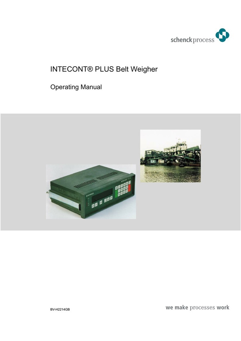
Schenck process Intecont Satus User manual

INTECONT® Satus
Belt Weigher
Operating Manual
BV-H2346GB

PASS - Service you can rely on.
Fast, comprehensive, anywhere in the world
Quality and reliability are the cornerstones of our company’s philosophy. That is why we consider a
comprehensive service concept simply par for the course, from strict quality control, installation and
commissioning through to seamless support across the entire product life cycle.
With over 30 service stations and over 180 service specialists, you can count on us to be there whenever – and
wherever – you need us. It doesn’t matter where you are, our specialists are there to advise and assist with the
best in worldwide, personal, comprehensive service.
During office hours, service specialists from all divisions are on hand to analyse problems and failures.
Look at www.schenckprocess.com for your nearest Schenck Process Location.
Customised to meet your requirements, our comprehensive Process Advanced Service System provides you
with the best service. Are you looking for individual, perfect-fit service solutions?
Then our, the modular service system PASS, is the ticket. It covers the entire service spectrum, from simple
inspections through to full service. Interested? Then find out more about the individual components at
www.schenckprocess.com/en/service.
Free 24 h Emergency Service Hotline in Germany
Are you experiencing a failure or problem outside normal office hours? Our service staff are on call around the
clock to deal with failures, service planning and other emergencies.
J+49 171 2 251195 Heavy and Light excluding Static Weighing Equipment
J+49 172 6 501700 Transport Automation and Static Weighing Equipment
© by Schenck Process GmbH, 2008
Pallaswiesenstraße 100, 64293 Darmstadt, Germany
J+49 61 51-15 31 0
www.schenckprocess.com
All information is given without obligation. All specifications are subject to change.
Note: Translation of the original instructions

Contents
1 Safety Instructions ........................................................1
2 Commissioning Flow Chart.................................................3
3 Housing Dimensions ......................................................4
4 Connecting the Device.....................................................5
4.1 Load Cells ...............................................................7
4.2 Speed input ..............................................................8
4.3 Digital inputs..............................................................8
4.4 Pulse output point for totalizing counter-impulse ..................................9
4.5 Relay outputs .............................................................9
5 Technical data and replacement parts .......................................11
5.1 Technical Data ...........................................................11
5.2 Supplied and replacement parts..............................................12
6 Overview ...............................................................13
7 Operation ..............................................................16
7.1 Mains voltage ON.........................................................16
7.2 Normal display ...........................................................16
7.3 Event messages..........................................................17
7.4 Function distributor........................................................19
7.5 Display test and version number .............................................20
7.6 Read parameters .........................................................20
8 Quick guide.............................................................21
9 Setup Program ..........................................................23
9.1 Adjustment functions ......................................................23
9.2 Belt circuit LB ............................................................23
9.3 Taring TW...............................................................25
9.4 Weight Control CW........................................................26
9.5 Setting the time ..........................................................27
10 Service values ..........................................................29
11 Parametrization .........................................................31
11.1 General Information .......................................................31
11.2 Preselecting the parameters ................................................32
11.3 Parameter Entry ..........................................................33
11.4 Load Preconfigured Parameters .............................................33
11.5 Set option ...............................................................34
11.5 Overview of Parameters....................................................35
12 Event messages .........................................................58
13 Fieldbusses.............................................................61
13.1 General Information .......................................................61
13.2 Structure of user data......................................................63
13.3 Fieldbus data ............................................................64
13.4 User data diagnosis .......................................................67
14 PROFIBUS DP...........................................................70
14.1 Guidelines for commissioning ...............................................70
14.2 Functionality of the Profibus connection........................................70
14.3 Structure of user data......................................................70
14.4 Proficbus DP master settings ................................................71
14.5 Diagnosis and Troubleshooting ..............................................71
14.6 Profibus module (VPB8020).................................................72
INTECONT® Satus Operating Manual BV-H2346GB / 0833 I 1
© Schenck Process

15 DeviceNet ..............................................................74
15.1 Guidelines for commissioning ...............................................74
15.2 Functionality of the DeviceNet connection ......................................74
15.3 Structure of user data......................................................74
15.4 DeviceNet master settings ..................................................74
15.5 Diagnosis and Troubleshooting ..............................................75
15.6 DeviceNet module (VCB8020) ..............................................76
16 Modbus ................................................................78
16.1 Guidelines for commissioning ...............................................78
16.2 Functionality of the Modbus connection ........................................78
16.2.1 Data Format .............................................................78
16.3 Function codes (FC).......................................................79
16.4 Securing transmission .....................................................79
16.5 Error codes..............................................................80
16.6 Subscriber addresses......................................................80
16.7 Process values ...........................................................80
16.8 Example telegrams........................................................80
16.9 Modbus master settings ....................................................81
16.10 Diagnosis and Troubleshooting ..............................................81
16.11 EasyServe Fieldbus view ...................................................81
16.12 XES3 serial interface ......................................................82
17 Ethernet................................................................83
17.1 Terms and Definitions .....................................................83
17.2 General TCP/IP Settings ...................................................83
17.3 Modbus/TCP ............................................................84
17.3.1 Guidelines for commissioning ...............................................84
17.3.2 Ethernet functionality ......................................................84
17.3.3 Modbus/TCP master settings ................................................85
17.3.4 Diagnosis and Troubleshooting ..............................................85
17.3.5 ‘Communication Host’ (S9) event message .....................................86
17.4 Ethernet/IP ..............................................................87
17.4.1 User Data Structure.......................................................87
17.4.2 ‘Communication Host’ S 9 event message .....................................87
17.4.3 EasyServe Fieldbus View...................................................88
17.4.4 Configuration of the Ethernet/IP Server (INTECONT Satus) ........................88
17.4.5 Configuration of the network in “RSLogix 5000" .................................89
18 Web Server .............................................................91
Index .........................................................93
I 2 BV-H2346GB / 0833 Operating Manual INTECONT® Satus
© Schenck Process

The Manual
This manual describes the INTECONT evaluation electronics.®Satus, hereafter referred to
as ‘the device’
The following will be explained:
–Mode of operation
–Connection diagrams
–Accessories
–Parametrization
–Fieldbus communication
for device version VKG 20790
The manual is valid for devices with the firmware version VBW 20790 - 01 or higher
INTECONT® Satus Operating Manual BV-H2346GB / 0833 1
© Schenck Process

- Space for notes -
2 BV-H2346GB / 0833 Operating Manual INTECONT® Satus
© Schenck Process

1 Safety Instructions
Intended Application
The measuring system with connected mechanical components is intended solely for
weigh tasks and related control applications. Use for any other purpose is considered
to be unintended use.
Sources of Risk
If the measuring system has been correctly installed and commissioned, it does not
pose any danger during weigh operations.
Hazards may arise when the system is used for control operations or for transporting
weighed goods. Potential hazards may then arise from e.g. additional devices through
which the weighed goods are passed or metered. Minor risks may arise in these
situations if the measuring system is used or operated by untrained personnel.
The measuring system may be used as a component in a more complex system. The
system licensee is fully responsible for the operating safety of the system.
Identifying residual hazards
This symbol identifies potential hazards that could lead to injury or even death in
extreme cases.
This symbol identifies potential hazards that could result in damage to the measuring
system or other system components.
Personnel
Preparation, assembly, commissioning, operation, maintenance and servicing may
only be carried out by qualified personnel.
All persons who use the measuring system in any way must know and observe the
safety instructions and those sections of the operating manual relevant to them.
It is the responsibility of the licensee to oblige the operating personnel to comply with
all regulations and instructions as they appear in the operating manual.
Changing parameters
Parameters determine the mode of operation of the measuring system. Only
personnel familiar with the device’s mode of operation may alter these parameters
(e.g. after training by SCHENCK Process GmbH). Incorrectly set parameters may
cause injury or material damage. Furthermore they may also cause considerable
disruption to weigh operations.
Password
Passwords safeguard the parameters against unauthorized alteration. The measuring
system licensee must ensure that the password is handled responsibly.
Safety Instructions
INTECONT® Satus Operating Manual BV-H2346GB / 0833 1
© Schenck Process

Acknowledging Event Messages
Event messages may only be acknowledged once the error has been rectified.
Ensure that any connected peripheral devices are functioning correctly before
acknowledging an event. Any connected control systems in particular must be in safe
state.
Maintenance and Service
All warning and instruction signs on the scales must be observed.
The measuring system must be shut down before work is performed on mechanical
equipment or peripheral devices (control systems in particular). Steps must be taken
to ensure the measuring system cannot be started inadvertently.
The power supply must be disconnected before work is performed on electrical
equipment.
Moisture and Humidity
All scales parts, electrical components in particular, must be protected from moisture
and humidity when the housing is opened for e.g. maintenance and service. In other
respects the protection classes of the housing must be observed.
Design Modifications
Schenck Process GmbH assumes no liability or guarantee for any design
modifications made to the measuring system or additional components fitted to it that
were not supplied by Schenck Process GmbH. This especially applies to alterations
which could affect the operating safety of the measuring system.
Replacing Parts
If parts must be replaced in the course of a repair, only original spare parts from
Schenck Process GmbH may be used. The use of other spare parts will void the
warranty.
Safety Instructions
2 BV-H2346GB / 0833 Operating Manual INTECONT® Satus
© Schenck Process

2 Commissioning Flow Chart
Commissioning Flow Chart
INTECONT® Satus Operating Manual BV-H2346GB / 0833 3
© Schenck Process
vh234614.cdr
Setting Parameters
for Blocks A, B, C (15 Parameters)
Chapterl
3+4
Chapter
5 + 6.1
Chapter
10
Chapter
8
Chapter
13
Powering-up and
Awaiting System Start
Mechanical and
Electrical Installation
Execute Setup Programs
Belt Circuit
Taring
Set Time
Set Limit Values
for Parameter Block F (3 Parameters)
Set
Fieldbus Communication
for Blocks L, L + T, or L + U
Chapter
10
Fig. 1: Commissioning Flow Chart

3 Housing Dimensions
The INTECONT®Satus is an electronic weigh system for belt weighers.
The VKG 20790 stainless steel protection class IP 65 casing is designed for horizontal
installation. The device may also be attached to the wall if the lid is rotated (downward cable
outlet).
Figure 1 shows the housing dimensions.
Figure 2 shows the drilling template for wall mounting. The parts required for mounting are
supplied with the device.
Housing Dimensions
4 BV-H2346GB / 0833 Operating Manual INTECONT® Satus
© Schenck Process
Fig. 2:
Fig. 3.

4 Connecting the Device
Figure 3 shows the location of the terminals
Connecting the Device
INTECONT® Satus Operating Manual BV-H2346GB / 0833 5
© Schenck Process
Fig. 4
1: Power supply (mains voltage)
2: Serial interface S1 (RS 232) - reserved for service-
program EasyServe
3: Serial interface S2 (RS 232) - unused
4: Serial interface S3 (RS 485) - reserved for Fieldbus-
communication MODBUS
5: Namur inputs/pulse-output point
6: Digital outputs
7: Digital inputs
8: Analog output - reserved for actual production
9: Load cell connection
10: USB CONNECTION - unused
11: Network connection (Ethernet)
12: Connector for optional Fieldbus module
Screened lines (load cell connection, serial interfaces) are bared in the device and
attached to the rail with isolated clamps for pull-relief.
Fig. 5:

Meaning of the LEDs
System Block:
1 PWRST (green): Supply voltage present
2 Idle: (yellow): Indication of system load. Greater operating time = Lower load
3 Fault (red): Error message
5 SYS-CL (yellow): System clock, blinks in normal operation
4, 6 Diag (green / red): no function
Network Block:
1 Link (green): Ethernet connection available
2 FDX (yellow): Full duplex
3 100 (red): 100 Mbaud (otherwise 10 Mbaud)
Connecting the Device
6 BV-H2346GB / 0833 Operating Manual INTECONT® Satus
© Schenck Process
Abb. 6:

4.1 Load Cells
Connecting the Device 4.1 Load Cells
INTECONT® Satus Operating Manual BV-H2346GB / 0833 7
© Schenck Process
Fig. 7: Connection of load cell (Process)

4.3 Digital inputs Connecting the Device
8 BV-H2346GB / 0833 Operating Manual INTECONT® Satus
© Schenck Process
4.2 Speed input
4.3 Digital inputs
Fig. 8: Speed input diagram connection
Fig. 9: Inputs connection diagram

Connecting the Device 4.5 Relay outputs
INTECONT® Satus Operating Manual BV-H2346GB / 0833 9
© Schenck Process
4.4 Pulse output point for totalizing counter-impulse
55
5
6
+
OUT5+
OUT5-
+24 VDC
-
XNA
Fig. 10: Impulse output connection diagram
4.5 Relay outputs
Fig. 11: Relay outputs connection diagram

- space for notes -
4.5 Relay outputs Connecting the Device
10 BV-H2346GB / 0833 Operating Manual INTECONT® Satus
© Schenck Process

5 Technical data and replacement parts
5.1 Technical Data
View LCD back lighting. 1 cell 20 characters. Characters
12,4mm high
Keyboard 6 keys
Supply voltage 100-240 VAC +10% -15%, 50-60Hz, max. 10 VA
Housing Stainless steel 1.4301, deep drawn, IP 65
Temperature range Service temperature: -30...+60 °C
Measuring ciruit Suppy voltage: 5V alternating current
supply
Range –20mV…+20mV;
Load cell impedance: Rmin 80Ω
Cable length: max. 500m
Units kg, t, lb; kg/h, t/h, lb/h;
Taring to be started via digital input or keyboard
Belt monitoring zero-drop-out; Belt load >max/<min
Binary inputs
3 x Optocoupler, 18-36 VDC, typ. 5 mA
1 x NAMUR, max. 5V, 0,04-3000Hz
assigned signal
Ack. event
Tare
External event
Tacho input
Binary outputs
4 x relay, 230 VAC, 60W max.
Pulse output
Optocoupler, 18-36VDC, max. 50 mA/10Hz
Running
Belt load Q>Max
Alarm
Belt load Q<Min
Totalizing counter pulses
Analog output
0–20mA, 12 Bit, max. Burden 500ΩFeedrate
Serial connections
Interface 1: RS 232
Interface 2: RS 232
Interface 3: RS 485,2/4-wire
Ethernet
Optional PROFIBUS DPV0, DeviceNet, Ethernet/IP
EasyServe
- not used –
Modbus fieldbus
Modbus/TCP fieldbus/EasyServe
Technical data and replacement parts 5.1 Technical Data
INTECONT® Satus Operating Manual BV-H2346GB / 0833 11
© Schenck Process

5.2 Supplied and replacement parts
Systems Type Material number
INTECONT Satus, Stainless steel housing IP65 VKG 20790 V040007.B01
INTECONT Satus with Profibus board VKG 20792 V060127.B01
INTECONT Satus with DeviceNet board VKG 20793 V060128.B01
INTECONT Satus with Ethernet/IP board VKG 20795 V060129.B01
Options
Profibus board VPB 20701 V040033.B01
DeviceNet board VCB 20700 V040031.B01
Ethernet/IP board VET 20700 V040035.B01
Spare parts
Cover with keyboard in preparation
Load cell plug (dongle) VDO20700 V040013.B01
EasyServe
Software and cable in preparation
Software (CD) VPC 20150 E144541.01
Cable for EasyServe, 9p/3p V052410.B01
5.2 Supplied and replacement parts Technical data and replacement parts
12 BV-H2346GB / 0833 Operating Manual INTECONT® Satus
© Schenck Process

6 Overview
Keyboard: Flexible membrane keyboard with action point
·Preselect display
·Select function
·Increase or decrease the blinking digit to enter a
number
·Switch to the left or right to continue entering the
number.
FUNC or ESC Open function distributor or abort entry
ENT ·Start functions
·Confirm entry
Some definitions:
I = Feed rate quantity of material per unit of time transported
by the belt conveyor
in kg/h or t/h
Z = Flow rate amount of material transported in kg or t = feed
rate x feed time
V = Belt conveyor speed in m/s
Q = Belt load in kg/m
Weight of material on one meter of belt
Measuring principle
Belt load Q and speed V are continuously measured and factored together.
The result is the feed rate I, from which the flow rate is determined
I in kg/h
Q in kg/m
V in m/s
Zero Drop Out:
Totalizing can be suppressed with measurements around the zero point so that the counter
stops when the belt idles (refer to parameters H09 and H10).
Measuring technique:
–High-precision AC-voltage amplifier with continuous zero-point and range correction.
–High-resolution analog-digital converter
–Effective suppression of external noise
–32 Bit Microcontroller
–Unlimited storage of counter readings, configuration and adjustment presets.
Overview
INTECONT® Satus Operating Manual BV-H2346GB / 0833 13
© Schenck Process

The block circuit diagram shows all inputs and outputs.
100-240VAC = Power supply
COUNTER = Pulse output point for connection of an external totalizing
counter.
ANALOG = Analog outputs for the feed rate
SERIAL = Serial interface for EasyServe and host computer
LC = Load cell for determining belt-load Q
D = Speed sensor for determining belt speed v.
If the belt speed is constant, D can be ignored for simple
measuring tasks.
W-IN (DO1) = Control output for belt drive
Closed = On
Q-MAX (DO2) = Relay output for Q-max monitoring
Open = Limit value exceeded.
ALARM (DO3) = Relay output for alarms
Open = Alarm
Q-MIN (DO4) = Relay output for Q-min monitoring
Open = Limit value exceeded.
Overview
14 BV-H2346GB / 0833 Operating Manual INTECONT® Satus
© Schenck Process
Table of contents
Other Schenck process Measuring Instrument manuals