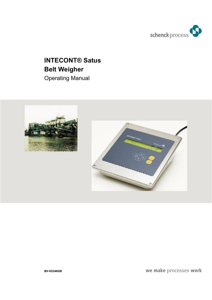
Schenck process Intecont Plus Belt Weigher User manual

INTECONT® PLUS Belt Weigher
Operating Manual
BV-H2214GB

PASS - Service you can rely on.
Fast, comprehensive, anywhere in the world
Quality and reliability are the cornerstones of our company’s philosophy. That is why we consider a comprehensive
service concept simply par for the course, from strict quality control, installation and commissioning through to seamless
support across the entire product life cycle.
With over 30 service stations and over 180 service specialists, you can count on us to be there whenever – and
wherever – you need us. It doesn’t matter where you are, our specialists are there to advise and assist with the best in
worldwide, personal, comprehensive service.
During office hours, service specialists from all divisions are on hand to analyse problems and failures.
Look at www.schenckprocess.com for your nearest Schenck Process Location.
Customised to meet your requirements, our comprehensive Process Advanced Service System provides you with the
best service. Are you looking for individual, perfect-fit service solutions?
Then our, the modular service system PASS, is the ticket. It covers the entire service spectrum, from simple inspections
through to full service. Interested? Then find out more about the individual components at
www.schenckprocess.com/en/service.
Free 24 h Emergency Service Hotline in Germany
Are you experiencing a failure or problem outside normal office hours? Our service staff are on call around the clock to
deal with failures, service planning and other emergencies.
J+49 171 2 251195 Heavy and Light excluding Static Weighing Equipment
J+49 172 6 501700 Transport Automation and Static Weighing Equipment
© by Schenck Process GmbH, 2008
Pallaswiesenstraße 100, 64293 Darmstadt, Germany
J+49 61 51-15 31 0
www.schenckprocess.com
All information is given without obligation. All specifications are subject to change.
Note: Translation of the original instructions

Contents
1 Overview......................................................................1
2 Control .......................................................................4
Power ON ··································································4
Signal Lamps································································4
Normal Displays ·····························································5
Control In Normal Mode ·······················································5
Event Messages ·····························································6
Function Distributor ···························································8
Display Test and Version Number ···············································8
Batching Mode ······························································9
Visual Make-up ·····························································11
Keyboard Mode ····························································11
Activate/Deactivate EasyServe ················································12
Prefeeder··································································12
Printing ···································································12
Zero Setting································································16
Read Parameters ···························································17
3 Control Overview ..............................................................19
4 Operating Principle ............................................................21
5. Technical Data ................................................................25
6. Characteristics ................................................................29
7 Setting Programs..............................................................33
Function Distributor ··························································33
Calibrating Functions·························································34
Belt Circuit LB ······························································34
TareTW···································································35
Weight Check CW ···························································36
SetTime ··································································38
Simulation Mode ····························································38
8 Service Values ................................................................39
9. Parameterization .............................................................43
Preselect Parameters .....................................................44
Enter Parameters ........................................................44
Hardware Configuration ...................................................45
Parameters Overview......................................................46
10 Event Messages ..............................................................85
System Messages S.......................................................85
Electrics E ..............................................................85
Calibration C.............................................................86
Maximum H .............................................................87
Minimum L ..............................................................87
Batching ................................................................88
Signal Lamps ............................................................88
11 Commissioning ...............................................................85
0837
INTECONT PLUS VBW
CONTENTS
BV-H2214 GB I - 1
Transmission to third parties and reproduction of
this documentation are not permitted. Schenck
Process GmbH reserves all rights of ownership
and copyrights.
Technische
Redaktion PDE-RD

How To Operate Your INTECONT···············································85
Mechanical Prerequisites ·····················································86
Electrical Prerequisites ·······················································86
Enter Parameters ···························································87
Functional Check ···························································88
Calibration ·································································89
Check Using Check Weight ···················································89
Check Belt Speed ···························································90
Check Using Material ························································90
Automatic Zero Setting ·······················································91
Belt Run Monitoring ·························································91
Belt Influence Compensation BIC ···············································92
Control for Point of Discharge CPD··············································92
Cosine Pendulum ···························································93
Test Plug ··································································93
12 Details ......................................................................93
Start/Stop..............................................................93
Batching Without Clearance.................................................95
Batching With Clearance ...................................................98
Data Flow Diagram.......................................................100
Connection Diagram......................................................103
Base Card .............................................................103
Option Card ............................................................105
Weighing Platforms ......................................................107
1. Effective Platform Length ................................................107
2. Check Weight QPRF ...................................................108
3. Conveyor Belt Inclination ................................................109
Printer Connectivity ......................................................110
13 Replacement Instructions .......................................................111
Replacing INTECONT PLUS FIP —> INTECONT PLUS VEG......................111
0837
VBW INTECONT PLUS
CONTENTS
BV-H2214 GB I - 2
Transmission to third parties and reproduction of
this documentation are not permitted. Schenck
Process GmbH reserves all rights of ownership
and copyrights.
Technische
Redaktion PDE-RD
This manual applies to software version: VBW 20600-08
Edition : 0837

1Overview
What Is The INTECONT:
INTECONT PLUS is designed as measuring and
evaluation system for
Belt Weighers
Solids Flow Meters
Mass Flow Meters
Mass Flow Feeders
Weighfeeders
Loss-in-weight Feeders
Three system versions are available:
1. Without option card (standard)
2. With option card VFE 610V for additional
input/outputs and printer
3. With option card for fieldbus
VSS021V : Modbus/S5
VPB 020V: Profibus
VCB020V: DeviceNet
VET020V: MODBUS/TCP
VET022V: ETHERNET/IP
This manual applies to belt weighers using the fully
equipped INTECONT variant.
For Further Reading:
Fieldbus manual BVH2220
SS-RK512 (3964R) FH 458
Modbus (Comp) FH 525
Display:
5x7-dotmatrix with 6 mm character height
Upper display left : running message
right : delivery rate in kg or t
Lower display left : event messages
right : selectable
feed rate, belt speed
etc.
Display can be changed over to American units.
LEDs:
2 green and 3 red LEDs
Green LEDs : Ready
Red LEDs : Error or limit value
messages
Keyboard:
Flexible membranes with tactile touch
gB Start/stop measurement
TU Preselect lower display
Select functions
iReset counter
GFUNC Call function distributor and
event texts
ODEL Acknowledge event messages
Delete input
0837
INTECONT PLUS VBW
Overview
BV-H2214 GB 1
Transmission to third parties and reproduction of
this documentation are not permitted.
SchenckProcess GmbH reserves all rights of
ownership and copyrights.
Technische
Redaktion PDE-RD
O Z1=1200 0kg
E1 I = 1000kg/h

NESC Abort function
fENT Start function
Acknowledge input
PDAT Prepare input
B9 Enter parameters
KL Enter sign and decimal point
Some Definitions:
I = Feed rate in kg/hr or t/hr
Material amount discharged from belt
per unit time
Z = Delivery rate in kg or t
Material amount fed out = feed rate x feed time
V = Belt speed in m/s
Q = Belt load in kg/m
Material weight on one belt meter
Measuring Principle:
Belt load Q and speed V are continuously measured
and multiplied.
The result is feed rate I used to determine delivery
rate.
I in kg/hr
Q in kg/m
V in m/s
Measurement techniques:
nPrecision AC voltage amplifier with continuous
correction of zero point and range
nHighly resolving analog-to-digital converter
The integrated method is designed to efficiently
suppress line voltage interferences.
n16-bit microcontroller
nUnlimited storage of counter readings,
configuration and calibration data.
The basic diagram shows all inputs and outputs.
L/C = Load cell for acquisition of belt load Q
D = Speed transducer
S = Belt circuit sensor for automatic belt
influence compensation BIC
(non-standard)
24 V = Power supply
V = Speed transducer
Q = Load cell
ANALOG= Analog output selectable for feed rate,
belt load, belt speed
SERIAL = Serial interfaces for printer and host
computer
MIN = Relay output for limit value monitoring
Open = MIN value exceeded down
0837
VBW INTECONT PLUS
Overview
BV-H2214 GB 2
Technische
Redaktion PDE-RD
Transmission to third parties and reproduction of
this documentation are not permitted. Schenck
Process GmbH reserves all rights of ownership
and copyrights.
O Z1 = 1500 kg
I = 100 kg/h

MAX = Relay output for limit value monitoring
Open = MAX value exceeded up
Feed rate, belt load, or belt speed, can be
monitoring separately for excess of MIN
and MAX values.
FAULT = Relay output for alarms
Open = Alarm
FULL = Relay output for full feed in batching
mode
Closed = full feed
DRIBBLE = Relay output for dribble feed
Closed = dribble feed
MOTOR = Control output for belt drive
Closed = ON
PREF. = Control output for prefeeder
Closed = On
RELEASE
=
Release signal for totalization
H = Release
ON/OFF = Start scale and totalization.
High = ON
OFF = Stop
Low = STOP
COUNTER= Pulse output for connection of external
totalizing counter
For simple measuring tasks, with constant belt speed,
speed transducer D can be omitted.
0837
INTECONT PLUS VBW
Overview
BV-H2214 GB 3
Transmission to third parties and reproduction of
this documentation are not permitted.
SchenckProcess GmbH reserves all rights of
ownership and copyrights.
Technische
Redaktion PDE-RD

2Control
Power ON
During power failure
Counter readings
Counter pulses not yet output
Preselected normal displays
Service values, e.g. ON-time
remain stored for an endless period of time.
The internal clock continues running for approx. 5
days.
After power-on, display and lamps are automatically
tested before version number of system is displayed
for some seconds to be then replaced by the normal
displays.
Message E1
reports power failure and can be defined as ALARM or
WARNING.
ALARM:
Red lampXand message E1 are
flashing.
To start scale, first acknowledge
message.
WARNING:
Signal lampXremains dark,
message E1 does not flash.
Start/stop scale automatically or in
manual. No acknowledgement is
required.
OLets you acknowledge event
message.
Signal Lamps
a(green) POWER OK
lights if all power supplies are OK.
b(green) CPU OK
lights if microprocessor is ready to
operate.
X(red) ALARM
flashes if an Alarm event is
available.
In addition, an event code appears
in lower display line.
MIN (red) MIN LIMIT VALUE
lights if feed rate limit value is
exceeded down.
MAX (red) MAX LIMIT VALUE
lights if feed rate limit value is
exceeded up.
READY:
The two green signal lamps must be lit, and no Alarm
message available.
0837
VBW INTECONT PLUS
Control
BV-H2214 GB 4
Technische
Redaktion PDE-RD
Transmission to third parties and reproduction of
this documentation are not permitted. Schenck
Process GmbH reserves all rights of ownership
and copyrights.
Z1=2500 kg
E1 I = 0 kg/h
Z1=2500 kg
E1 I = 0 kg/h

Normal Displays
Upper Display
Left Rotating point as running message.
Scale has started, totalized amount
and feed rate are acquired.
In stop state of scale (point stands
still) only belt load and belt speed are
measured.
Right Totalizing counter Z1
Lower Display
Left Event message, alphanumerically
coded, e.g. E1 for power failure.
Right Selectable display
TU Select display
Counter Z2 Z2 = 6000 kg
Counter Z3 Z3 = 1000 kg
Feed rate I = 1000 kg/hr
Feed rate Ir = 50.00 % 1)
Belt load Q = 10.000 kg/m
Belt load Qr = 50.0% 2)
Belt speed V = 0.0500 m/s
Batching displays Zb, ZI, Zd, Nb 3)
1) related to nominal feed rate
2) related to nominal belt load
3) see “Batching Mode”.
Display formats and units of counters Z1, Z2, Z3 and I
can be selected separately.
Control In Normal Mode
gStart totalization
Prerequisite : External release signal
available (selectable)
START source (B06)
set to OP or Keyboard
Mode active.
Feature : Rotating point in left field
of upper display
BStop totalization
Feature : Point stands still
Belt load and belt speed continue
being measured.
iReset totalizing counters.
This function has to be activated with
parameters A10 or A11.
1Enter number of desired counter
(1 or 2).
Counter no. : _
Counter 3 cannot be reset. In case of
overflow, counting resumes from 0.
fAcknowledge input.
NCorrect faulty input or accidental use
of DELETE key.
TU Select lower display
(see “Normal Display”).
OAcknowledge event messages.
GCall further functions, e.g. display
event messages, calibration.
NExit function distributor.
0837
INTECONT PLUS VBW
Control
BV-H2214 GB 5
Transmission to third parties and reproduction of
this documentation are not permitted.
SchenckProcess GmbH reserves all rights of
ownership and copyrights.
Technische
Redaktion PDE-RD
O Z1 = 50 000 kg
Z2 = 60 0 kg/h

Event Messages
Definitions
All important scale functions are internally monitored,
and faults are reported by event message.
For troubleshooting details, see “ Event Messages”
item.
Message E1 Power Failure
Group code (e.g. E) and number (e.g. 1) appear in left
field of lower display.
In addition, an explanatory text can be called up.
The events are organized into 4 classes. The
assignment between event and class can be selected
using relevant parameter.
nALARM Display is underscored and
flashes.
Red signal lamp Xflashes.
Totalization stops, scale is
inoperable.
Start:
If cause of Alarm has been
removed and error message
acknowledged.
Acknowledgement:
If cause of Alarm has not been
removed, flashing stops but
message is still on display.
nWARNING 1 Display permanent and
underscored Totalization goes on.
Acknowledgement:
If cause of fault is still present,
underscores are faded out.
nWARNING 2 Display permanent, not
underscored
Acknowledgement:
None
nIGNORE No event monitoring, save
MIN/MAX messages via contact
outputs and signal lamps.
If several events occur at the same time, the most
significant event is displayed first.
Priority: Alarm, Warning 1, Warning 2
Operation
OAcknowledge events of ALARM and
WARNING 1 classes after
elimination of fault. If several events
are available, acknowledge one
after the other.
Display event texts:
GCall function distributor.
TU Scroll “Show Event” function into
lower display field.
fSelect function.
0837
VBW INTECONT PLUS
Control
BV-H2214 GB 6
Technische
Redaktion PDE-RD
Transmission to third parties and reproduction of
this documentation are not permitted. Schenck
Process GmbH reserves all rights of ownership
and copyrights.
Z1 = 2500 kg
E1 I = 0 kg/h

Display shows
event name e.g. No Release
event code e.g. S2
and a note e.g. Parameter O07.
The note informs the operator of relevant parameter.
TU Let you view various events.
NReturn to normal displays.
List of Events
The events are listed in accordance with display
priority.
System messages S1 Memory Error
S2 No Release*
S3 Scale Maintenance ON
S4 Maintenance Interval
Electrics
S7 Simulation active
S9 Host Communication
Electrics E1 Power Failure
E2 Namur Error Tacho*
E3 Namur Error Sensor*
E6 Error Ext. Event
Material flow B1 Out of Tolerance
B4 BATCH Actual Value MAX
Calibration C C1 L/C Input *
C2 Tacho Input *
C3 Belt Skew
C4 Belt Drift
C5 Tare Correction > MAX
C7 ZERO Time
C8 Slip Error
C9 Tare Diff > MAX
Maximum H H1 I > MAX
H2 Load > MAX
H3 v > MAX
H4 L/C Input > MAX
Minimum L L1 I < MIN
L2 Load < MIN
L3 v < MIN
L4 L/C Input < MIN
I = Feed Rate
V = Belt Speed
L/C = Load Cell
* Fault on device or cabling
Contact Outputs
General Alarm available until acknowledged
MIN/MAX Outputs independent of event class,
active also in IGNORE class.
Limit values are reported as long
as event is available and only
with active scale.
0837
INTECONT PLUS VBW
Control
BV-H2214 GB 7
Transmission to third parties and reproduction of
this documentation are not permitted.
SchenckProcess GmbH reserves all rights of
ownership and copyrights.
Technische
Redaktion PDE-RD
1. Event S 2 = O 0 7
No Release

Function Distributor
The function distributor lets you call further functions,
or dialogs.
GCall function distributor.
If no event is available, display shows
function selected last.
fStart function.
NReturn to normal display and/or
abort function.
TU Scroll through function distributor
Display Events E
Test Display
START/STOP Prefeeder Z
Service Values
Batch Number B
Print Counter Readings
>0< Zero Set
START/STOP Keyboard Mode
Activate/Deactivate EasyServe
Programming
Calibrating Functions S
Read Parameters
Enter Parameters S
Load Default Parameters S
Print Parameters
Status Report
Tare S
START/STOP Simulation
Check Weight S
Imp/Belt Circuit S
Set Time S
Programming and calibrating functions lead to further
menus you can move through using cursor keys.
B = If batching mode is selected, you can access
additional functions in main distributor.
Abort Batch
Deselect Batch
Batch Number
Print Batch
Make-up
Next = Belt Empty
S = Calibrating functions protected by password.
Prompt is output after call of function.
E = If an event is available
Z = Iif activated via parameter
Moving through function distributor has no effect on
weighing functions.
Display Test and Version Number
Lets you check displays and signal lamps.
G
TU
f
Call display test.
1. Display elements flash
rhythmically.
2. Version number is displayed for
apr. 3 s.
Test terminates automatically.
Example:
VBW : Belt Weigher
20600-00 : Version number
0837
VBW INTECONT PLUS
Control
BV-H2214 GB 8
Technische
Redaktion PDE-RD
Transmission to third parties and reproduction of
this documentation are not permitted. Schenck
Process GmbH reserves all rights of ownership
and copyrights.
Function
Display Events
INTECONT PLUS
VBW 20600-00 2482

Batching Mode
Additional Displays
Upper display : If batching mode is selected, a
totals sign is displayed left of
running message.
Lower display : Use cursor keys to scroll 4
additional values into display field.
U1. Zb = Batch setpoint
2. ZI = Batch actual value
Amount already
discharged
3. Zd = Batch residual value
Amount not yet
discharged
Zd=Zb-ZI
4. Nb = Consecutive batch
number
Use “Batch Number”
function to set initial value.
Before a batch starts, ZI and Zd indicate the amounts
fed out during previous batch.
If you deselect batching mode (Deselect Batch functi-
on), displays are disabled but enabled again upon
next selection.
The display format corresponds to the format of
counter 1.
Select Batching Mode
Selection of batching mode enables batching,
however, no batch is started yet.
Condition: scale OFF and function activated via
parameter A07.
GCall function distributor.
TU Scroll “Select Batch” into display
field.
fSelect function.
System prompts for input of batch setpoint.
If batch is selected from external PC, setpoint input is
omitted.
Enter Setpoint
Setpoint prompt is output automatically upon selection
or can be started in manual when batch is complete
(scale OFF).
If batching mode is deselected or a batch is running,
no input is possible.
When presetting batch setpoint via fieldbus
(Parameter I09 Batch Source = FB), no input is
possible either. This also applies to the input of batch
number and make-up setpoint.
PPrepare setpoint input.
19 Enter setpoint in kg or t
Max. 9 digits including decimal
point.
The unit is that of counter 1.
fAcknowledge input.
NAbort input, old setpoint remains
stored.
ODelete faulty digits.
0837
INTECONT PLUS VBW
Control
BV-H2214 GB 9
Transmission to third parties and reproduction of
this documentation are not permitted.
SchenckProcess GmbH reserves all rights of
ownership and copyrights.
Technische
Redaktion PDE-RD
O Z1 = 2500 kg
ZI = 400 kg
. Setpoint Batch
Zb=...... kg

Start and Abort
gStart batch, process starts.
Display ZI moves from 0 towards
setpoint
Display Zd moves from setpoint
towards 0.
BAbort batch.
Batching continues upon next start
command.
Deselect Batch
Lets you deselect batching mode, i.e. mode is removed
from active functions available.
Totals sign disappears from upper display, batching
values ZI, Zd, Zb and Nb are no longer available, but
remain stored.
Prerequisites : Batch complete, or aborted using
“Abort Batch” function; scale OFF.
GT
f
Call function distributor,
select “Deselect Batch” function,
and acknowledge.
Use “Select Batch” function to reactivate batching
mode.
Old values ZI, Zd, Zb and Nb can be viewed again.
Abort Batch
This function lets you abort a running batch, i.e.
batching immediately stops.
Batching mode remains selected.
New batch starts upon next start command, old batch
is not resumed.
Use “Make-up” function to complete old batch.
GT Call function distributor and select
“Abort Batch” function.
fAcknowledge.
You can also abort batch using the P02 contact.
Make-up
Lets you add a selected amount of material to a batch
aborted or complete.
Prerequisites : Running batch complete, scale OFF.
No batch printout.
Display ZI : Batch actual setpoint resumes from
achieved value.
Display Zd : Batch residual value remains
unchanged.
Display Zbn : Make-up setpoint
Display Zdn : Batch residual value of make-up
amount
Zdn = Zbn - make-up amount
already fed.
You can scroll all displays into lower display field
using cursor keys.
Zdn and Zbn are available only until start of next
batch.
GT Call function distributor and select
“Make-up” function.
fAcknowledge.
System prompts for input of
make-up setpoint Zbn in kg or t.
The units is that of Counter 1.
PUntil start of make-up, setpoint Zbn
can be changed.
gB Start or abort make-up
If make-up batch is complete, normal batch starts
upon next start command.
For new make-up, call function again.
“Abort Batch” function also aborts make-up
operations.
0837
VBW INTECONT PLUS
Control
BV-H2214 GB 10
Technische
Redaktion PDE-RD
Transmission to third parties and reproduction of
this documentation are not permitted. Schenck
Process GmbH reserves all rights of ownership
and copyrights.

Batch Number Nb
Select a number incrementing by 1 after start of every
new batch.
The consecutive number is printed in batch report and
indicated in lower display line.
Belonging to previous batch, make-up operations are
not counted.
GT Call function distributor and select
“Batch Number” function.
fAcknowledge.
Prompt Nb = —- is output.
fAcquire input.
NAbort input.
Old number remains stored.
Current number can be changed also while a batch is
running.
Next = Belt Empty
One-off changeover to clearance mode.
Next batch is controlled via prefeeder. When batch is
complete, conveyor belt still performs approx. 1/2 belt
circuit.
Prerequisites : Scale OFF,
batch complete,
prefeeder control present and
active.
Batching mode without clearance.
GT Call function distributor and select
“Next - Belt Empty” function.
fAcknowledge.
gStart batch.
Visual Make-up
A batch report can be printed only if batch is complete
(setpoint reached).
If an unspecified amount is to be batched using the
START/STOP keys, the results can be printed using a
little trick:
1. Call “Select Batch” function.
2. Enter very high batch setpoint,
e.g. 999999999 kg.
3. Scroll batch actual value ZI into lower display field.
4. Start scale.
5. If desired amount ZI is reached, stop scale.
6. Call “Abort Batch” function.
7. Start printing
(see “Print Batch”).
Make-up can be performed only before print
command. To start next batch, resume from item 4.
Keyboard Mode
This function lets you place the selected control
source for
Start/Stop, Batch setpoint
on the INTECONT keyboard. If you deselect Keyboard
Mode, the old source is active again. When changing
over from external source (e.g. serial) to keyboard, the
Start/Stop status remains stored; vice versa, the
external signal is active.
GT Call function distributor and select
“Start Keyboard Mode” or “Stop
Keyboard Mode” functions.
Display feature:
You will know Keyboard Mode by the rectangle in the
upper left display field.
Condition :This function has to be activated
with the parameter A06.
0837
INTECONT PLUS VBW
Control
BV-H2214 GB 11
Transmission to third parties and reproduction of
this documentation are not permitted.
SchenckProcess GmbH reserves all rights of
ownership and copyrights.
Technische
Redaktion PDE-RD

Activate/Deactivate EasyServe
This function lets you control your INTECONT using
the “EasyServe” PC service tool.
GT Call function distributor and select
“Activate EasyServe” function.
Enter communication parameters using Block R.
Condition:This function has to be activated
with the parameter A09.
Note: Upon power failure, the current
status is stored, i.e. the “Activate
EasyServe” function needs not be
reselected.
Connection to PC can also be made using a 9-pole
SUB-D connector on X4 (RS 232 only) or a Phoenix
connector on X5 (RS232, RS422 or RS485).
See also Wiring Diagram in chapter DETAILS.
Prefeeder
The “Start/Stop Prefeeder” function lets you activate or
deactivate prefeeder. Select “Start”, and INTECONT
will control your prefeeder. In Stop state, material flow
is interrupted and scale can be tared.
Prerequisites : External prefeeder present and
controlled by INTECONT.
Activate function using parameter
N 01.
GT Call function distributor and select
“Start Prefeeder” or “Stop Prefeeder”
function.
fStart control signal.
Printing
The printing functions are available only if the option
card is present.
Print Batch
The batch report can be printed:
1. using “Print Batch” function
2. automatically after each complete batch
(Parameter J02 = YES).
Start of printing disables the “Make-up” function for the
current batch.
Prerequisites : Batch complete, scale OFF.
Print format : Order of sequence, line and column
divisions can be selected at will
(Parameter Block J).
GT Call function distributor and select
“Print Batch” function.
Start function.
NAbort printing.
Batch Number: Consecutive number of batch
20.11.02: Date and time
Batch Setpoint: Preset batch amount
Batch Actual Val.: Amount batched (actual value)
Totalizer 1:
Totalizing counter 1
Totalizer 2: Totalizing counter 2
Zero Set before: Feeder run time after last taring or
zeroing operation (see Service
Values)
Events : available during printing
0837
VBW INTECONT PLUS
Control
BV-H2214 GB 12
Technische
Redaktion PDE-RD
Transmission to third parties and reproduction of
this documentation are not permitted. Schenck
Process GmbH reserves all rights of ownership
and copyrights.
Batch Nummer 40
20.11.02 16:49:41
Batch Setpoint 0.150 t
Batch Actual Val. 0.150 t
Totalizer 1 0.806t
Totalizer 2 806.47 kg
Zero Set beforer 19 min.
Events
E1 Power Failure O01

Print Counter Readings (FMZ), Quantity Report
This report is identical with the batch report, however,
the numerical values are identified as sub-totals by
the # symbol.
If no batching mode is selected, batch number, batch
setpoint and batch actual value are not printed. This
type of report figures as “Quantity Report”.
Batch actual value [kg] # 998 #
etc.
Call:
1) Use “Print Counter Readings” function.
Unlike the “Print Batch” function, printing is
possible during running batch.
2) Printed automatically upon every event printout
(Parameter J03 = YES)
Print Parameters
Print complete parameter list with current values.
Inputs differing from default values are identified by *.
The list is complete with all possible event messages
and the current hardware assignment.
GT Call function distributor and select
“Print Parameters” function.
fStart function.
NAbort printing at any time.
Print Events
Parameter J03 lets you select/deselect printout of
event messages.
There are 3 options:
1. No printout (NO)
2. Print events (error)
3. Print events and counter readings (YES)
(see “Printer Counter Readings”)
L2 : Event code
W1 : Error class, e.g. WARNING 1
:Event has occurred
:Cause removed, event acknowledged, if
required.
Load<MIN: Explanation
Event is displayed on INTECONT as long as
available.
For more information, see “Event Messages” item.
0837
INTECONT PLUS VBW
Control
BV-H2214 GB 13
Transmission to third parties and reproduction of
this documentation are not permitted.
SchenckProcess GmbH reserves all rights of
ownership and copyrights.
Technische
Redaktion PDE-RD
PARAMETER PRINTOUT
INTECONT PLUS VBW 20600-01 2482
20.11.02 16:59:51
BLOCK A Dialog Behaviour
01 Language ENGLISH
02 Units SI
BLOCK B Rated Data
01 Feed Rate Unit ——— kg/h
02 Nominal Feed Rate * 1,000 t/h
etc.
20.11.02 11:45:21 L2 W1 Load > MAX
20.11.02 11:59:01 L2 W1 Load < MIN

Print Zero Setting Results
The result of the automatic zero setting function can
be printed automatically after every belt circuit.
Prerequisite:Parameter H 01 = YES (Auto Zero Active)
Parameter H09 = YES
Tare correction is the total of all zero point changes;
total tare additionally includes the basic tare.
Values correspond to same-name parameters
D 03/05.
Status Report
The status report can be printed at any time.
Reported are previous events, calibration results, and
SPC measurement values, e.g. feed rate variance.
SPC = Statistic Process Control
For individual data, see “Service Values” item.
GT Call function distributor and select
“Status Report” function.
fStart function.
NAbort printing at any time.
Zero Set before:
Zero point corrected by taring program or
manual/automatic zero setting.
Voltage ON-time:
Total voltage ON-time.
Feeder ON-time:
Total ON-time of conveyor belt and INTECONT.
Last password entry on:
Date of last password input for start of a service function
or parameter change.
Latest matkor change:
The matkor parameter lets you change feed rate and
totalization range.
SPC time:
Measuring time for SPC values “Qmax” and “TQ < MIN”. 0837
VBW INTECONT PLUS
Control
BV-H2214 GB 14
Technische
Redaktion PDE-RD
Transmission to third parties and reproduction of
this documentation are not permitted. Schenck
Process GmbH reserves all rights of ownership
and copyrights.
Print Zero Setting Results
Total Tare [kg/m] 50,23 Tare Correction T [kg/m] 1,56
STATUS REPORT INTECONT PLUS
25.11.02 13:37:12
Software : VBW 20600-01 2482
Hardware version : 1
Option card version : 1
Station address : 1
-------------------------------
Latest Report of: 25.11.02 12:13:13
------------ -------------------
SPC values:
Zero Set before : 4086 min
Voltage ON-time : 68 h
Feeder ON-time : 68 h
Latest password entry of : 22.11.02 17:02:12
Latest matkor change : 15.11.02 15:02:34
K05 SPC Time : 1 h
K06 SPC Filter : 1.00 h
Feed rate
Mean value Imitt : 0.15 %
Variance : 0.09 %
Belt load Q MAX : 0 %
Time Q MIN : 0 %
Totalizer 3 : 510 t
Belt skew : 0.00 %
Belt Drift : 0.00 cm
Latest taring results (max. 5) T in % of Qnenn
22.11.02 16:04:05 : 12.99 %
21.11.02 16:11:22 : 30.75 %
21.11.02 16:10:53 : 33.40 %
22.11.02 16:05:22 : 12.99 %
22.11.02 16:04:43 : 12.99 %
Test weight check of 16.06.03 16:23:17
25.11.02 09:06:28
Set/Act 0.9643
N05 BIC Active NO
Events since power on
1 * H03 v> MAX
1 * C07 Set Time To Zero
1 * E01 Power Failure

SPC filter:
Filter time for SPC values “mean value” and “variance”
Mean value Imitt:
Feed rate mean value exponentially filtered using the
SPC filter time related to nominal feed rate.
Variance:
Feed rate variance related to the square of nominal feed
rate.
Belt load QMAX:
Maximum belt load during last few hours limited by SPC
time related to nominal belt load.
Time Q < MIN:
Total time during which belt load was below Qmin
(Parameter F 05), evaluated over the past few hours
(SPC time).
Last taring results (max. 5):
Results (total tare) of last 5 zero point or tare corrections,
related to nominal belt load.
Test weight check on :
Date and time of last check using check weight,
performed using “Weight Check CW” setting program.
BIC active:
indicates whether automatic belt influence
compensation is active, or not.
Events report:
lists number and type of events occurred after last
printout.
If no report has been printed yet, counting starts from
time of power-up.
Counter 3:
Totalizing counter 3
Belt skew:
indicates change in belt length in % of total belt length
(Parameter D06).
Belt drift:
indicates belt drift in cm.
Feed Rate Diagram
Printed automatically after status report, the feed rate
diagram shows the current feed rate value in percent
of nominal feed rate. The report period is determined
by Parameter K 05 “SPC Time” .
The actual diagram resolution is higher than shown in
sample.
Feed rate 50 dots for nominal feed rate
Time : 32 dots for time K 05
Units : t/h, h
Initialisation : upon power-up and change of
Parameter K 05.
Symbol “>” : Feed rate exceeds 140 %
0837
INTECONT PLUS VBW
Control
BV-H2214 GB 15
Transmission to third parties and reproduction of
this documentation are not permitted.
SchenckProcess GmbH reserves all rights of
ownership and copyrights.
Technische
Redaktion PDE-RD
Feed Rate in Percent Pnenn
0 20 40 60 80 100 120 140 %
- 6h * 5,000 t/h
- 5h * 10,000 t/h
- 4h * 20,000 t/h
-3h >
- 2h * 40,000 t/h
- 1h * 50,000 t/h
- 0h * 50,000 t/h

Zero Setting
The zero setting program is designed to acquire the belt
weigher’s zero point error over one or multiple integer
belt circuits.
In normal mode, value is used to correct current
measuring result.
If no automatic mode is selected, use program in regular
intervals.
During zero setting, totalizing counters stop counting.
Prerequisite:1. Conveyor belt totally unloaded.
If necessary, abort program.
User “Start Prefeeder” function, if
available.
2. Belt running,
indicated automatically.
3. No batch active; batching mode can
remain active.
4. This function has to be activated with
the parameter A08.
Call:
G
TU
f
Call Zero Setting function and start.
If belt is not running, program aborts
and requests START.
Program running:
Upper display: Residual run time in % of total run
time.
Lower display: Zero point error in %, related to
nominal belt load.
NAbort program at any time.
Program complete:
Upper display: Deviation of zero point from
previous zero setting operation in %
of nominal belt load.
Dev=+:error increased
Dev = - : error decreased.
Lower display: Deviation of zero point from basic
tare in % of nominal belt load.
Taring program corrects basic tare
during calibration.
Acquire result, or view for information and reject.
fAcquire result.
Scale zero point is corrected.
NAbort program.
Result is rejected.
Restart prefeeder.
Event messages:
1- C7 Zero setting time elapsed.
Deselect message, if not desired.
2- Value Excessive
Zeroing range exceeded; clean
scale and retare, if necessary.
3. Note:
The function setting to zero can also be
started via the digital input P05. The
program is started by a positive flank of the
contact. The result is automatically accepted
if it is within the admissible zero setting limit
(5% of the nominal belt load). An
ackowledgement of the result is not
necessary. The calibration program can only
be aborted in its active phase.
0837
VBW INTECONT PLUS
Control
BV-H2214 GB 16
Technische
Redaktion PDE-RD
Transmission to third parties and reproduction of
this documentation are not permitted. Schenck
Process GmbH reserves all rights of ownership
and copyrights.
0. >0< 70.2 %
Tarkor 1.12 %
0. Dev. 70.2 %
Tarkor 1.12 %
Table of contents
Other Schenck process Measuring Instrument manuals