Schertler Arthur ART48-MICLINE X User manual

ACOUSTIC FIDELITY
arthur
FORMAT48 - MICLINE X
USER MANUAL
V1

INTRODUCTION
Thank you for choosing the ART48-MIC/LINE X module. This high-end, Class-A, 4-channel input
unit features sophisticated MIC/LINE switching capabilities that enable either a microphone or a
line level sound source to be connected to each channel as and when needed, with automatic
adaptation of the sensitivity range and input impedance. Fully compatible with all existing Arthur48
and X mixer modules, and equipped with six separately controllable AUX SENDS on each channel,
the MIC/LINE X is ideally suited to both live sound use and studio applications where more exible
input and output options are required.
Like all Arthur modules, the MIC/LINE X features circuits that are built using single, discrete Class-A
electronic components and pure high-voltage DC amps (without a single capacitor in the signal path),
offering 30 dB headroom and low noise, as well as unparalleled stability, warmth and transparency.
To make the most of your MIC/LINE X module and to ensure trouble-free operation, please read
this manual carefully before using the unit for the rst time. It’s also advisable to retain the
manual for future reference.
For instructions on installing and combining the various Arthur modules and advice on starting up
the mixer, please read the separate ART48 ASSEMBLY manual.
SAFETY FIRST!
Safety is of major importance when operating any electrical equipment, so please note the following:
On a product, a lightning ash within a triangle indicates the
presence of uninsulated “dangerous voltage” within the product
enclosure. This may be of sufcient magnitude to cause risk of
electric shock.
ELECTRICAL SAFETY
This information applies to all modules and power supplies that form your ARTHUR mixer:
Before connecting your mixer to the mains, make sure that the mains voltage does not exceed
the voltage specied on the mixer/power supply.
Do not use your mixer if its power supply, cable or plug are not in perfect condition. Replace
these as necessary, using the exact models/types specied. If any xed cables need replacing,
this should be done by a suitably qualied professional.
Your mixer should only be connected to a mains socket with a ground protection system.
When setting up or installing your mixer, make sure that the mains socket and the power supply’s
mains cable and plug are easily accessible.
Do not, under any circumstances, defeat the safety purpose of the polarized or grounding-type
plug. A polarized plug has two blades with one wider than the other. A grounding-type plug has
two blades and a third grounding prong. The wide blade and third prong are provided for your
safety. If the supplied plug does not t your mains socket, consult an electrician for replacement
of the obsolete socket.
Do not expose your mixer to rain or any other water (even in small amounts). Do not use the
mixer near water.
Avoid spilling drinks or any other liquids on the mixer.
IMPORTANT SAFETY INFORMATION

IMPORTANT SAFETY INFORMATION
Do not operate your mixer in excessively humid conditions. Avoid excessive heat from sunshine,
re or similar. If your mixer is being used in a dusty environment, make sure it is adequately
protected.
Avoid installing your mixer near any heat sources such as radiators, heat registers, stoves, or
other heat-producing apparatus (including ampliers).
Do not put any sources of open ame (e.g. candles or pyrotechnics) on or near your mixer.
Do not cover your mixer during use, or obstruct the ventilation ow in any way.
Unplug your mixer during lightning storms, or if it is not going to be used for a while. (Remove
the plug from the mains socket to completely disconnect the mixer.)
Your mixer does not contain any “user serviceable” parts. Servicing and/or repairs should only
be carried out by qualied personnel. See MAINTENANCE AND REPAIR (below).
OPERATIONAL SAFETY
During installation or live performances, make sure that your mixer’s power supply cable cannot
be walked on, tripped over or “pinched” – particularly at sockets, around waste bins etc. Also
make sure that the power supply cable is not “stressed” at its point of connection to the mixer.
To avoid interference, do not install your mixer near power transformers, TV sets, RF transmitters,
electric motors, or any other sources of electrical energy.
To avoid potential accidents, only use attachments, accessories and other equipment such as
carts, stands, tripods, brackets or cases that are specied or recommended by the manufacturer,
or sold with your mixer.
Loud volume levels can cause irreparable damage to hearing, so avoid the following while using
your mixer:
- acoustic feedback (never point microphones directly at a loudspeaker)
- high levels of distortion
- impulse noises (loud “pops”) that can occur when a device is switched on/off, connected to or
disconnected from a system.
MAINTENANCE AND REPAIR
Your mixer can be carefully cleaned, as necessary, using a dry cloth. No water must be used.
When cleaning, do not use any solvents (such as acetone or alcohol). These could damage the
mixer’s nish and its labeling.
Visually check your mixer on a regular basis for any signs of wear and tear or damage, but do
not attempt any kind of servicing or repair.
If your mixer malfunctions, or has been damaged, e.g. if the power supply/cable or plug is
damaged, liquid has been spilled or objects have fallen inside, the mixer has been exposed
to rain or moisture, does not operate normally, or has been dropped, please call your nearest
Schertler technical assistance centre. (For more information, contact us at the address on the last
page of this manual.)

The MIC/LINE X’s four input channels are identically
equipped.
1. XLR input: This input can receive balanced signals from
-63 dBu to +6 dBu in MIC mode - a range of 69 dB, which
therefore permits you to connect any audio signal to the mic
unit. (Also see 5 and 6 below.)
2. GAIN: Adjusting the Gain affects the amplication rate
of the input amplier. A weak signal is amplied to a nominal
level of 0 dBV and a stronger signal is attenuated so that a
nominal signal level of 0 dB is always present at the output
of the mic input amp. (Also see 5 and 6 below.)
On the VU level meters, positioned at the side of each
channel fader, you can “read” the amount of gain set. Turn
up the gain to a point where the red overload occasionally
shows. But don’t worry too much about this. Thanks to
the amount of headroom from input to output on Arthur,
even strong overloads can be absorbed by the mixer’s
electronics without resulting in distortion.
3. P48: In MIC mode, depressing the P48 button (red
light), delivers 48V of phantom power to the microphone,
which, in most cases will be a condenser or active ribbon
type. A dynamic mic cannot normally “see” phantom power
(as the name suggests), but passive ribbon mics could be
permanently damaged by it. Only use this button with mics
that you denitely know require phantom power in order
to work. Note: The internal circuitry raises the 48V slowly,
to avoid “pops” and to protect the microphone. Therefore,
allow around 10 seconds for the mic to be working fully.
4. PHASE (ø): This swaps the “hot” and “cold” aspects
of the input signal, inverting its phase by 180°. This can be
helpful if, for example, two microphones are positioned at a
distance, or reverse-faced (i.e. as with bottom and top snare
drum miking). Depressing the ø button on one mic means
that the reverse-faced mic will get “in phase”, or a distantly
placed mic (for certain frequencies at least), will become
ART48-MICLINE X
“better” in phase with a second mic. Note: The button positioning is subjective and the results really
need to be evaluated through listening.
5. UNITY and 6. LINE-MIC: The LINE-MIC (gain) button (6) adapts the signal processing to the
nature of the input signal. When this button is set to LINE (green light), the impedance is automatically
adapted for line signals and the 48V phantom power is deactivated to prevent any damage to the “line”
device connected. When the channel is switched to LINE mode, the sensitivity range adapts from -21
dBu to +8 dBu. You can automatically set the nominal level at 0 dBV by activating the UNITY button (5).
7. INSERT/BALANCED DIRECT OUT and 9. INSERT: The INSERT (9) works in a similar way to
inserts on other mixers. However, a related “bypass” button (7) offers additional possibilities. When
this is depressed, the signal in the mixer is interrupted and the Insert will work in the usual way. By
16.
1.
3. 4.
2. 5.
6. 7.
8. 9.
10. 11.
12.
13.
14.
15.
17.
18.

connecting a mono jack, you get the simple output line signal on the “tip”. By
connecting a standard stereo phone jack, you get the (output) signal from the “tip”
(send) and the return signal will be connected to the mixer through the “ring” (return)
of the jack. When the button is not depressed, the signal will not be interrupted by the
insertion of a phone jack into the Insert. Here, the insert connection works as a sleeve
out or “dry line out post input amp”. You can connect a simple mono phone jack or a
stereo phone jack to the insert. The unbalanced line signal will be transmitted through
the “tip” of the phone jack. Red light = depressed (Insert functionality active.) White
light = not depressed (Insert functionality bypassed).
8. LOW CUT: The Low Cut button limits low frequencies at 100 Hz/second order,
cutting out unwanted low frequencies from “boomy” signals. The lter can also be
helpful in shaping signals from smaller instruments (violin, mandolin etc).
10. RESONANCE: The resonance lter is a kind of notch lter, but one that is
gradually adjustable over its attenuation level. This lter is designed to avoid, or at
least attenuate, feedback on acoustic instruments that are miked up in live situations
using pickups, e.g. the SCHERTLER DYN series. A double bass or ‘cello might get in
resonance at ca. 150 Hz, whereas guitars and similar musical instruments will do so
at ca. 240 Hz. The Q is very high, cutting out a very narrow band at the respective
frequency.
If the RESONANCE control is set to the FLAT (far left) position it will not be active,
thus having no effect on the incoming signal. When the rotary control is turned slowly
clockwise, the lter will gradually attenuate at the chosen frequency (see 11 below).
Turn the control to the point where a “boomy” feedback effect can be minimized
without cutting too much from the signal and subsequently losing some of its lower
end.
11. 150Hz-240Hz button: This lets you select the frequency. When the button is not
depressed (red light), the lter will attenuate at 150 Hz. When the button is depressed
(blue light), the lter will attenuate at 240 Hz.
12 and 13 EQ section: The EQ ON button (13) bypasses or activates the lter
section. (White light = bypassed, green light/depressed = activated.). This is helpful
for comparing a lter conguration with the unltered sound. Sound engineers often
bypass lters to avoid a reduction in sound quality, letting the signal go through the
lter circuitry. However, Arthur’s innovative circuitry enables loss of sound to be kept
to an absolute minimum, so you should hardly hear any difference in sound quality
regardless of whether the lters have been bypassed or are active.
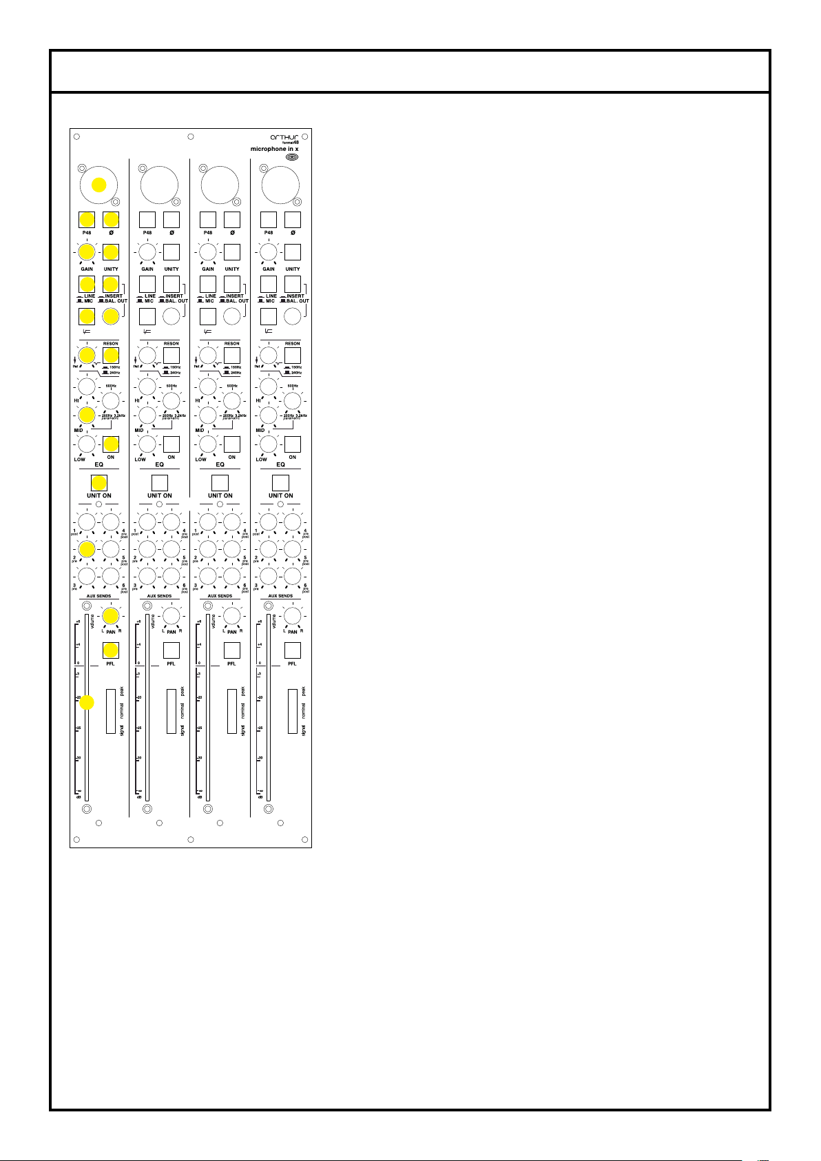
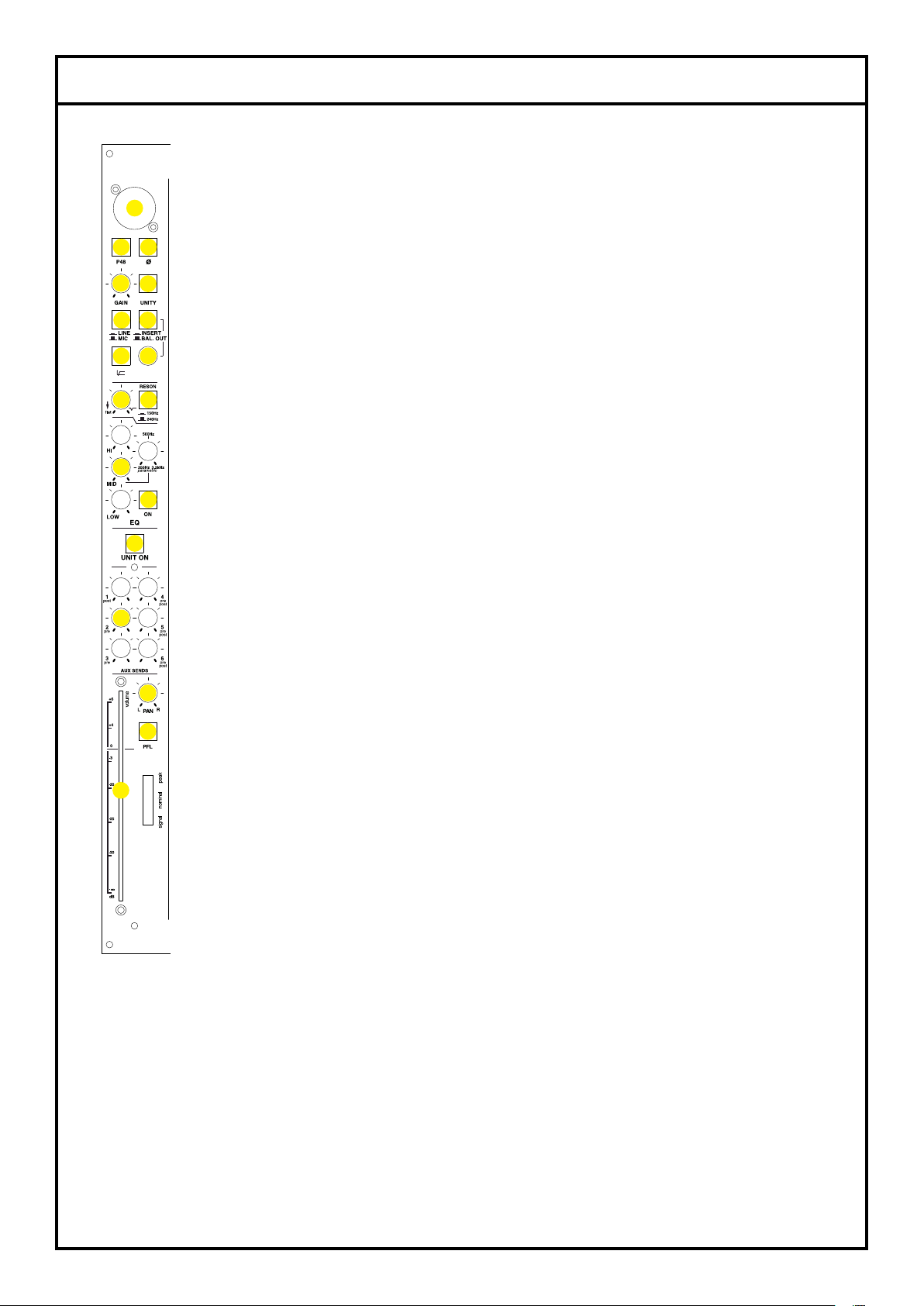
ART48-MICLINE X
16.
1.
3. 4.
2. 5.
6. 7.
8. 9.
10. 11.
12.
13.
14.
15.
17.
18.
Note: The EQ ON button will not bypass the RESONANCE lter.
EQ controls (12): The HI control lets you tune the high range of the audio spectrum (from 4 kHz)
by +/- 14 dB with a slope of 18 dB / octave. The 3rd order structure “keeps” the circle of inuence
within the lter’s audio band so as not to overlap with the MID lters. This makes adjustment of the
higher frequencies more accurate.
The MID control, together with the MID FREQ control, acts on frequencies within a wide mid range
of 250 Hz to 3 kHz, with amplication or attenuation of +/- 12 dB. (The MID control affects the
amplitude (amplication or attenuation) while the MID FREQ control affects the frequency.)
The LOW control lets you adjust the signal by +/-16 dB up to 110 Hz with a slope of 12 dB / octave.
The higher order prevents the low frequencies from overlapping with the parametric mid, making
adjustment of the lower frequencies more accurate.

ART48-MICLINE X
The HI, MID and LOW rotary controls all have a detent at their mid positions. This
indicates the lter’s “at” position.
14. UNIT ON/OFF: The UNIT ON button connects/disconnects that channel’s output
routing for all outputs (AUX1 to AUX6 and L/R), except the PFL routing. This function is
similar to the MUTE button used on other mixers, but here the functionality is reversed.
When the button is depressed, all outputs get connected - whereas a MUTE button
disconnects the output when pressed. Also, whereas a MUTE button normally only
disconnects the L/R routing (the channel’s fader), this button affects all outputs. Being
able to switch off a channel strip makes sense in order to prevent the signal from still
going through to stage monitors, or to the input of the reverb unit for example. Note:
Even if the button is in the switched off position (not depressed, white light), the PFL
and INSERT will still be ready to function, (as shown by the lights on their respective
buttons), even though all other button lights are off.
15. AUX SENDS: There are six rotary controls – one for the level control of each
send (AUX1 to AUX 6). This enables each individual AUX SEND to be controlled
independently from the others.
The signal to AUX1 is “taken” post fade because this auxiliary line can be used with
the Spring unit for reverb effect, while AUX2 and AUX3 are pre fade for use with
stage monitors. The other 3 AUX can be independently assigned pre- or post fade on
the Master X unit.
This means that you can have an AUX conguration of up to one post and ve pre (1
effect + 5 monitors) or up to four post and two pre (4 effects + 2 monitors).
The level of the AUX sends can be read on the MASTER X unit’s dedicated VU meter.
16-18. Fader section: Operation of this fader section is identical to that on other
mixers. The channel faders and their associated functionality probably form the most
important part of the output process. In most cases, the signal(s) going through this
section will be mixed in the MASTER X and will appear on the main L/R outputs that
drive the recording device or the front-of-house PA speakers. This is the signal usually
heard by the public.
The PAN pot (16) enables the signal to be sent to the Left or Right master channel.
Its conguration is designed to guarantee minimum noise and maximum dynamics in
the central position. In this position, the signal ows to both channels at maximum
level. When the pot is set hard left, you will only hear the signal on the left channel.
While turning the pot from the left to the central position, the left channel’s signal
will not change, but the right channel’s signal will continuously increase, reaching its
maximum level at the central position - and vice versa.
16.
1.
3. 4.
2. 5.
6. 7.
8. 9.
10. 11.
12.
13.
14.
15.
17.
18.
As well as being a traditional PFL (pre fade listen), the PFL button (17) also serves as an additional
AUX send, albeit without the possibility to set any levels. All channels that have their PFL activated
(red light) will be mixed in the MASTER X unit and sent to the PFL output, controlled by the PFL
fader and “visible” on the Master X’s VU meter. This function can be useful if you have an
additional monitor and only need one signal, e.g. for a singer who only requires the “voice
channel”. Note: The PFL section still runs if the UNIT ON is deactivated (white light).
The channel fader (18) controls the total amount of signal going to the master. To exclude this
signal from the MASTER X without changing the fader position, simply switch the UNIT ON button
to its OFF position (white light). The button will then act as a MUTE.

ART48 - MIC/LINE X: SIGNAL FLOW
TECHNICAL INFORMATION

Input impedance:
Output impedance (Bal. DIR. OUT):
Maximum input level:
Maximum output level (headroom):
Sensitivity:
Total Gain (through Master X):
Frequency response: (-3 dB)
Low cut: (-3 dB)
Reson attenuation:
Low EQ:
Parametric Mid EQ:
High EQ:
Equivalent input noise (EIN):
Distortion (THD+N; @1 kHz):
-30 dBu input level
0 dBu output level
Power consumption:
Size & Weight:
4.6 kohm MIC mode
43 kohm LINE mode
240 ohm
+24 dBu (@1kHz; THD<0.5%) LINE mode
+30 dBu (@1kHz ; THD <0.5%)
-63 dBu to +6 dBu MIC mode
-21 dBu to +8 dBu LINE mode
72 dB
<10 Hz – 55 kHz
100 Hz (Shelving, 2nd order)
10 dB @ 150 Hz / 240 Hz
110 Hz (Shelving) -16 dB / +16 dB
250 Hz – 3 kHz -12 dB / +12 dB
4 kHz (Shelving) -14 dB / +14 dB
129.4 dB (Insert, 60 dB Gain, 150 ohm)
0.041% Total
0.04% (2nd harmonic)
0.019% (3rd harmonic)
0.0006% (4th harmonic)
0.0011% (5th harmonic)
420 mA
143x58x475mm; 1.75 kg
TECHNICAL INFORMATION

NOTES

NOTES

APPENDIX
WARRANTY
All Schertler products are covered by a limited two-year factory warranty (from the date of purchase)
in respect of manufacturer defects. Details can be obtained from your local dealer / representative.
Schertler S.A. strongly believes in “common sense”. Therefore, misuse of our products is not covered
under rights obtained through our warranty policy, or through internationally recognised terms and
conditions. For more information on warranty, please visit the Schertler website.
PRODUCT DISPOSAL
This product must not be disposed of in general household waste. It should be taken to a disposal
centre for electrical / electronic waste. Please note any local or national regulations that may be
applicable here.
TRADEMARKS
The SCHERTLER® name and logo are registered trade names / trademarks of SCHERTLER S.A.
Switzerland. All SCHERTLER® products use proprietary technology and are covered by one or
more worldwide patents.
DISCLAIMER
All information and technical specications published here are based on data that was available at
the time of publication. Schertler is, however, constantly aiming to improve its range of products and
therefore reserves the right to amend product specications and information without notice.
Schertler takes no responsibility for any direct or indirect damage (including loss of prot), which
arises as a result of, or in connection with the information in this manual.
COPYRIGHT
This manual is the property of Schertler S.A. and, as such, is subject to Swiss copyright law. No part
of this manual should be reproduced, edited or distributed without prior consent from Schertler.

Table of contents
Popular Control Unit manuals by other brands

Festo
Festo CAMC-G-S1 Translation of the original instructions

Honeywell
Honeywell MDC108200 installation guide

Girard Systems
Girard Systems GC946G installation guide

H3C
H3C PSR3000-54A manual

Apator Powogaz
Apator Powogaz APT-WMBUS-NA-1 operating manual

Axiometrix Solutions
Axiometrix Solutions imc C Series Getting started