Controls
Switches
Button
All the other inputs are aected by the ASYNC/SYNC control to either only have an
aect on the rising edge of the clock or immediately.
These inputs control the rate of counting.
These are the shift register inputs. The ASYNC/SYNC control similarly aects whether it will
shift only on a cloc or any time a pulse is received.
Inputs
All inputs are logic inputs with a threshold of around 2.8V that trigger on the rising
edge.
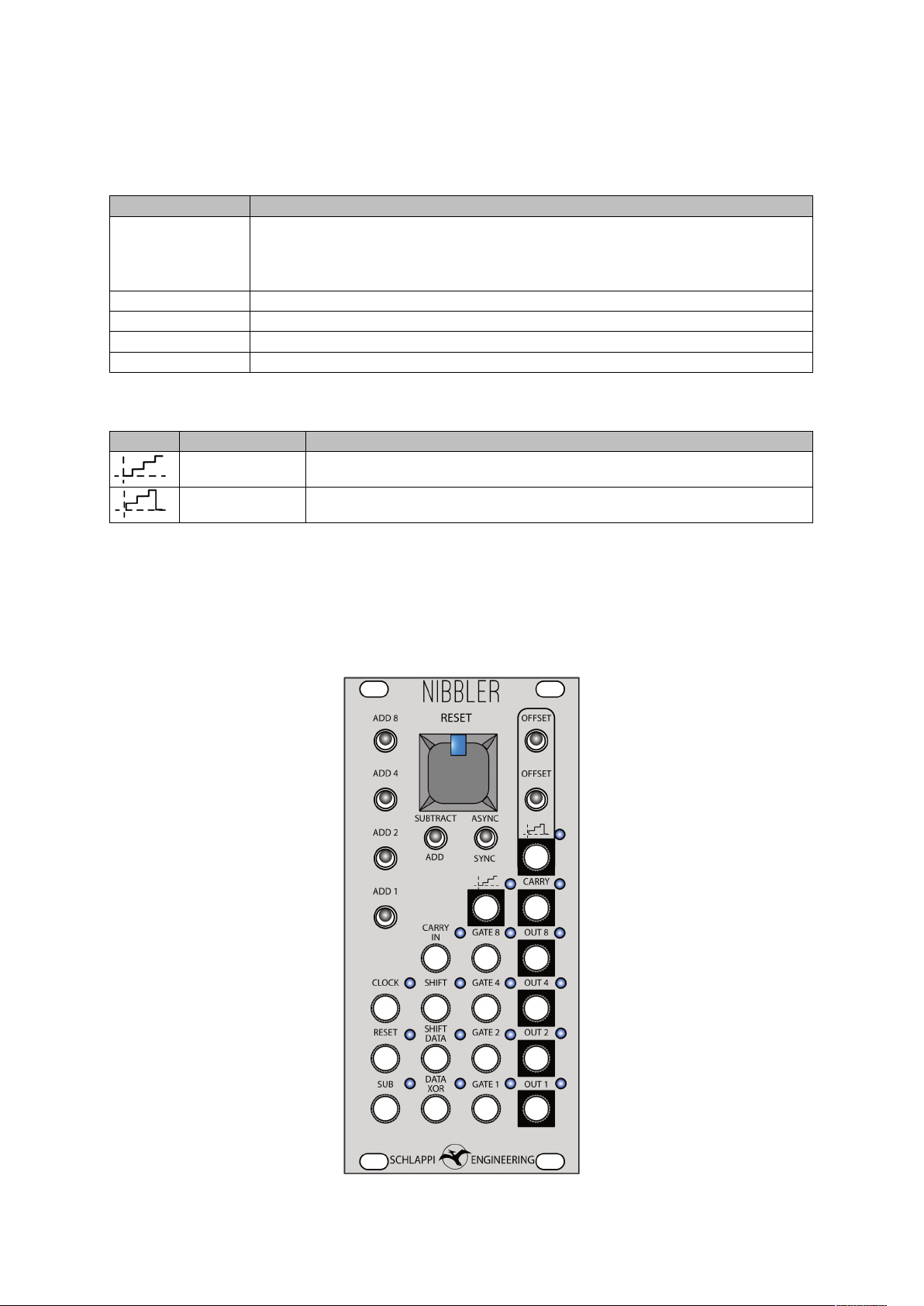
CONTROL DESCRIPTION
ADD 8 Adds 8 to the register
ADD 4 Adds 4 to the register
ADD 2 Adds 2 to the register
ADD 1 Adds 1 to the register
SUBTRACT/
ADD
Determines if the number formed by the ADD SWITCHES is added or
subtracted from the number already in the register
ASYNC/
SYNC
Determines if the output is updated only on a rising clock pulse (SYNC)
or every time an input is received (ASYNC)
OFFSET These two switches together set a phase oset for the second stepped
voltage. It can be 0º (both down), 45º (only bottom switch up), 90º (only
top switch up), or 180º (both switches up)
OFFSET
INPUT Description
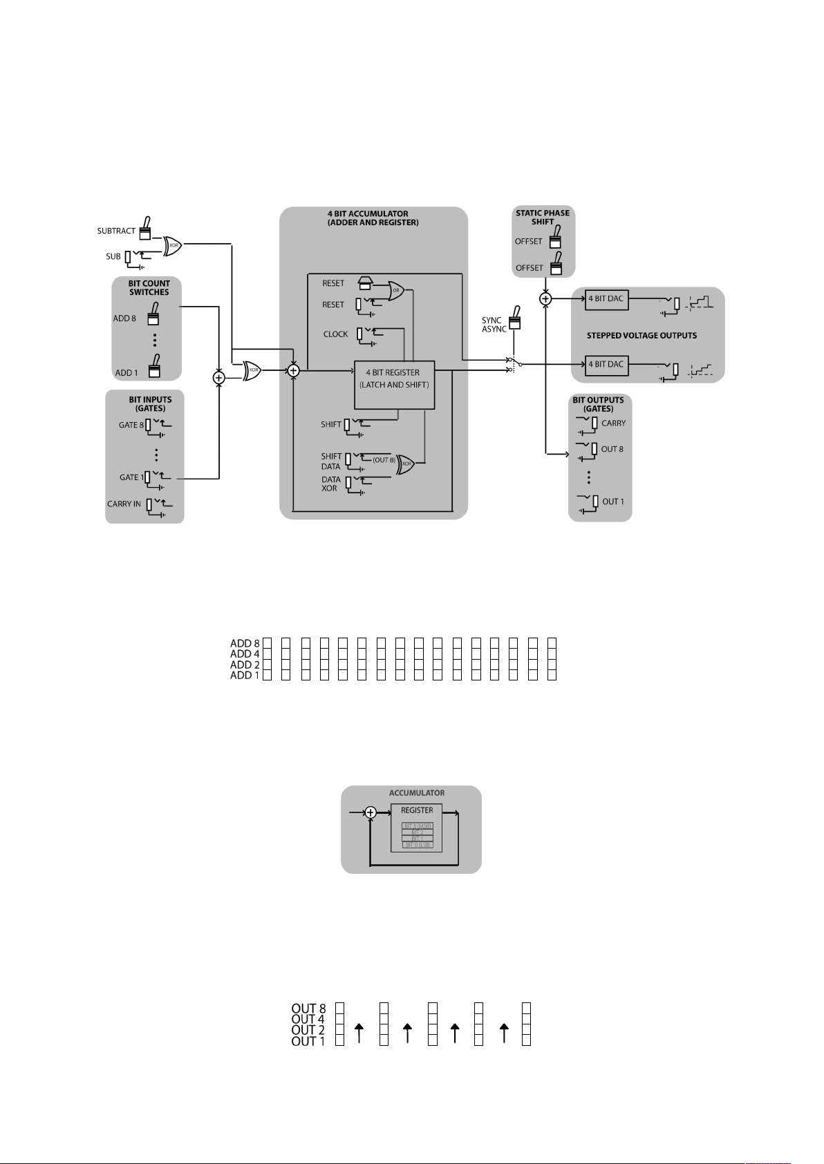
CLOCK Clock input, also used for audio rate frequency division purposes.
Necessary for most operations.
RESET Clears the register, setting all outputs to 0, AC coupled so it can be
used as a hard sync input at audio rate
SUB This input interacts with the SUBTRACT ADD switch to change the
state to the opposite of the current setting.
INPUT Description
CARRY IN Intended for chaining multiple Nibblers, to make a larger register by
patching a CARRY OUT to a carry in. Eectively the same as GATE
1.
GATE 1 Adds with the ADD 1 switch to set the rate of counting.
GATE 2 Adds with the ADD 2 switch to set the rate of counting.
GATE 4 Adds with the ADD 4 switch to set the rate of counting.
GATE 8 Adds with the ADD 5 switch to set the rate of counting.
INPUT Description
SHIFT While SHIFT is high in SYNC mode any clock pulse will shift the
contents of the register up one, or if in ASYNC mode it will shift on
any pulse on this input.
SHIFT DATA Replaces the input of the shift register. With no input the top bit
(OUT *)cycles around and enters from bottom.
DATA XOR Performs an XOR function with whatever data is at the input to the
shift register
CONTROL DESCRIPTION
RESET Clears the register, setting all outputs to 0